What is a capacitor and its main characteristics
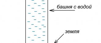
A capacitor is a radio component that works as a storage device for electrical energy. To make it clearer how it works, it can be thought of as a kind of small battery. Indicated by two parallel lines.
Designations of various types of capacitors in the diagrams. Most often, electrolytic capacitors fail, so it’s worth remembering their designation
The main characteristic of any type of capacitor is capacity. This is the amount of charge that it is able to accumulate. It is measured in Farads (abbreviated simply as the letter F or Ф), or rather, in smaller units:
- microfarads - µF is 10-6 farads,
- nanofarads - nF is 10-9 farads;
- picofarads - pF is 10-12 farads.
The second important characteristic is the rated voltage. This is the voltage at which long-term trouble-free operation is guaranteed. For example, 4700 uF 35 V, where 35 V is the nominal voltage of 35 volts.
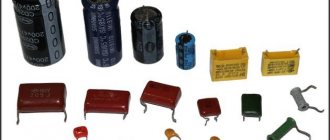
For large capacitors, the capacitance and voltage are indicated on the case
You cannot place a capacitor in a circuit with a higher voltage than that indicated on it. Otherwise, it will quickly fail.
You can use 50 volt capacitors instead of 25 volt capacitors. But this is sometimes impractical, since those that are designed for higher voltage are more expensive, and their dimensions are larger.
Characteristics of capacitors
The capacitor, depending on the state of the electrolyte and the material from which it consists, can be dry, liquid, oxide-semiconductor, oxide-metal. Liquid capacitors are well cooled, these devices can operate under significant loads and have such an important property as self-healing of the dielectric upon breakdown. The dry-type electrical devices under consideration have a fairly simple design, slightly less voltage loss and leakage current. At the moment, dry appliances are the most popular. The main advantages of electrolytic capacitors are their low cost, compact dimensions and high electrical capacity. Oxide analogs are polar (incorrect connection leads to breakdown).
Parallel and combined connection
There are other connection methods, namely combined and parallel connection of capacitors. Other physical laws apply to them.
Parallel capacitors
Capacitor energy
The voltage of the entire group when connecting capacitors in parallel is equal to the voltage of the smallest of them. That is, if there is a circuit of three capacitors for 16, 25 and 50 V, then the maximum that can be applied to them is 16 V. In such a circuit, the full voltage of the power source will be applied to each individual capacitor.
The capacity of such a battery is cumulative. This is caused by the virtual addition of the areas of the plates of all individual capacitors. In the language of physics it looks like this:
Ctotal par = C1 + C2 + … + Cn.
Why is such a connection needed? It is used to increase the capacitance of capacitors, for example, in the high-voltage part of welding inverters and many powerful power supplies.
Additional Information. A parallel connection allows you to reduce the overall internal resistance of the assembly, and therefore its heating. This way you can increase the service life of the container.
The combined (mixed) compound is the most complex. It contains both serial and parallel elements. Calculation of the parameters of such circuits is given with experience. For simplicity, it is customary to study it in a triangle, breaking it down into simpler parts.
Mixed compound
From the diagram it is obvious that capacitors C1 and C2 are connected in series. Their total capacity can be calculated using the formula described above - Ctotal last. Further the scheme is simplified. There are already two parallel capacitors Ctot.seq and C3. Calculated using the above formula Ctotal par. As a result, a difficult-to-understand circuit element turns into one equivalent capacitor. This technique describes a simplification algorithm with which you can calculate much more complex capacitor figures (square, cube, etc.).
Capacity calculation
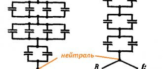
The capacitance of the capacitor for the electric motor is calculated based on the winding connection diagram - star or triangle.
In both cases, the general calculation formula is applied: Service = k x Iph/Unetwork, to which all parameters have the following designations:
- k – is a special coefficient. Its value is 2800 for the star circuit and 4800 for the delta circuit.
- Iph – rated stator current indicated on the information plate. If it is impossible to read, measurements are taken using special measuring clamps.
- Umains – supply voltage of 220 volts.
What is it and how does it work
In the simplest case, a capacitor consists of two conductive plates (plates) separated by a dielectric layer.
Between the plates there is a layer of dielectric - a material that does not conduct electric current well.
The plates are supplied with direct or alternating current. At the beginning, while the energy is stored, the energy consumption of the capacitor is high. As the container “fills,” it decreases. When the charge is fully charged, there is no current consumption at all, the power source seems to turn off. At this time, the capacitor itself begins to release the accumulated charge. That is, it temporarily becomes a kind of power source. That's why it is compared to a battery.
Types of capacitors
Capacitive elements are classified according to the type of dielectric used in the design.
Paper and metal-paper capacitors
The elements are used in circuits with constant or slightly pulsating voltage. The simplicity of the design results in a 10-25% decrease in the stability of characteristics and an increased amount of losses.
In paper capacitors, the aluminum foil plates are separated by paper. The assemblies are twisted and placed in a housing in the shape of a cylinder or rectangular parallelepiped.
The devices operate at temperatures -60...+125°C, with a rated voltage of up to 1600 V for low-voltage devices, above 1600 V for high-voltage devices and a capacity of up to tens of microfarads.
In metal-paper devices, instead of foil, a thin layer of metal is applied to dielectric paper. This helps to produce smaller elements. With minor breakdowns, self-healing of the dielectric is possible. Metal-paper elements are inferior to paper ones in terms of insulation resistance.
Electrolytic capacitors
The design of the products resembles paper ones. But in the manufacture of electrolytic cells, paper is impregnated with metal oxides.
In paperless electrolyte products, the oxide is applied to a metal electrode. Metal oxides have one-way conductivity, which makes the device polar.
In some models of electrolytic cells, the plates are made with grooves that increase the surface area of the electrode. Gaps in the space between the plates are eliminated by pouring electrolyte. This improves the capacitive properties of the product.
The large capacity of electrolytic devices—hundreds of microfarads—is used in filters to smooth out voltage ripples.
Aluminum electrolytic
In devices of this type, the anode plate is made of aluminum foil. The surface is coated with a metal oxide - a dielectric. The cathode plate is a solid or liquid electrolyte that is selected so that the oxide layer on the foil is restored during operation. Self-healing dielectric extends the operating time of the element.
Capacitors of this design require polarity. If you turn it back on, it will break the case.
Devices containing back-to-back polar assemblies are used in 2 directions. The capacity of aluminum electrolytic cells reaches several thousand microfarads.
Tantalum electrolytic
The anode electrode of such devices is made from a porous structure obtained by heating tantalum powder to +2000°C. The material looks like a sponge. Porosity increases surface area.
Using electrochemical oxidation, a layer of tantalum pentoxide up to 100 nanometers thick is applied to the anode. The solid dielectric is made from manganese dioxide. The finished structure is pressed into a compound - a special resin.
Tantalum products are used at current frequencies above 100 kHz. The capacitance is created up to hundreds of microfarads, with an operating voltage of up to 75 V.
Polymer
Capacitors use an electrolyte made of solid polymers, which provides a number of advantages:
- the service life increases to 50 thousand hours;
- parameters are saved during heating;
- the range of permissible current ripples is expanded;
- The resistance of the plates and leads does not bypass the capacitance.
Where and what are they used for?
As already mentioned, it is difficult to find a circuit without capacitors. They are used to solve a variety of problems:
- To smooth out surges in network voltage. In this case, they are placed at the input of devices, in front of microcircuits that are demanding on power parameters.
- To stabilize the output voltage of power supplies. In this case, you need to look for them before leaving.
Electrolytic cylindrical capacitors are often seen - Touch sensor (touch pads). In such devices, one of the “plates” of capacitors is a person. Or rather, his finger. Our body has a certain conductivity. This is what is used in touch sensors.
- To set the required rhythm of work. The charging time for capacitors of different capacities is different. In this case, the charge/discharge cycle of the capacitor remains constant. This is used in circuits where it is necessary to set a certain rhythm of work.
- Memory cells. The memory of computers, phones and other devices is a huge number of small capacitors. If it is charged, it is one, if it is discharged, it is zero.
- There are starting capacitors that help “accelerate” the engine. They accumulate a charge, then release it sharply, creating the required “push” to accelerate the motor.
- In photo flashes. The principle is the same. First, the charge is accumulated, then released, but converted into light.
Capacitors are common and their applications are wide. But you need to know how to connect them correctly.
Model overview
There are several popular models that can be found on sale.
It is worth noting that these models differ not in capacity, but in type of design:
- Metallized polypropylene versions of the SVV-60 brand. The cost of this version is about 300 rubles.
- NTS film brands are somewhat cheaper. With the same capacity, the cost is about 200 rubles.
- E92 – products of domestic manufacturers. Their cost is small - about 120-150 rubles for the same capacity.
There are other models, often differing in the type of dielectric used and the type of insulating material.
It is worth noting that on small electric motors used for domestic needs, for example, for a 200-400 W electric sharpener, you can not use a starting capacitor, but get by with one working capacitor, I have done this more than once - a working capacitor is quite enough. Another thing is if the electric motor starts with a significant load, then it is better to use a starting capacitor, which is connected in parallel with the working capacitor by pressing and holding the button while the electric motor accelerates, or using a special relay. The starting capacitor capacity is calculated by multiplying the working capacitor capacity by 2-2.5; this calculator uses 2.5.
It is worth remembering that as the asynchronous motor accelerates, it requires less capacitor capacity, i.e. You should not leave the starting capacitor connected for the entire operating time, because A large capacity at high speeds will cause overheating and failure of the electric motor.
Electrical capacity
When connecting devices for charge condensation, as a rule, the technician is interested in the electrical capacitance that will result.
Electrical capacity shows the ability of a two-terminal network to accumulate charge and is measured in farads. It may seem that the higher this value, the better, but in practice it is not possible to create all possible containers in the world, moreover, this is often not necessary, since all devices used every day use standard condensation devices.
You can connect several devices for condensation in a circuit, creating one condensing container, and the value of the characteristic value will depend on the type of connection, and there are long-known formulas for its calculation.
Permanent capacitors
Based on the nature of the change in electrical capacitance, capacitors are divided into devices with constant, variable capacitance or tuning ones. Let's look at each of the mentioned types in more detail. Devices whose capacitance does not change during operation, that is, it is constant (the capacitance value can still fluctuate within acceptable limits depending on the temperature), are permanent capacitors. There are also electrical appliances that change their electrical capacity during operation; they are called variables.
How to properly connect capacitors
To find out how to connect a capacitor correctly, you need to figure out exactly what type it is. There are a huge variety of these electronic devices. All capacitors are divided into two groups:
- polar (electrolytic) - when connecting them, it is necessary to take into account where the part has a positive and negative contact;
- non-polar (all others) - these capacitors are capable of operating on alternating current; they do not have positive and negative terminals.
Then you need to consider the design of the electronic component. From this point of view, capacitors can be:
- Inferential. They are connected to the board using thin copper legs, coated (tinned) with a layer of solder for protection.
- For surface mounting (SMD). Mainly used in compact electronics. Very miniature, often not exceeding 1 mm in diameter.
It is also important to take into account the operating voltage of the capacitor. This is especially important for electrolytic devices of this type, because if their rated voltage is exceeded, they will most likely explode, spraying boiling electrolyte in all directions.
Important! There are two notches on the cover of the electrolytic capacitor. These weak points serve to instantly depressurize the product in the event of excessive internal pressure. When repairing and adjusting equipment, avoid directing the notches onto your face or clothing. In an emergency, hot electrolyte may splash out from them.
The maximum voltage threshold is no less critical for other types of capacitors, especially those with small dimensions and unable to withstand overloads for a long time.
The last but not least important factor to consider when connecting capacitors is their capacitance. It is measured in microfarads (after Michael Faraday). This is their main characteristic, which is why capacitors are often called electrical capacitances. In some electronic devices, this parameter can deviate significantly, both downward and upward. In others, an error of 1% is unacceptable.
How do they conduct alternating current?
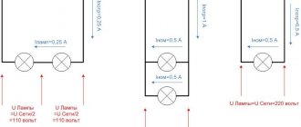
To see this with your own eyes, it is enough to assemble a simple diagram. First you need to turn on the lamp through capacitors C1 and C2 connected in parallel. The lamp will glow, but not very brightly. If we now add another capacitor C3, the glow of the lamp will noticeably increase, which indicates that the capacitors resist the passage of alternating current. Moreover, a parallel connection, i.e. Increasing the capacitance reduces this resistance.
Hence the conclusion: the larger the capacitance, the lower the resistance of the capacitor to the passage of alternating current. This resistance is called capacitive and is denoted in formulas as Xc. Xc also depends on the frequency of the current; the higher it is, the less Xc. This will be discussed a little later.
Another experiment can be done using an electricity meter, having first disconnected all consumers. To do this, you need to connect three 1 µF capacitors in parallel and simply plug them into a power outlet. Of course, you need to be extremely careful, or even solder a standard plug to the capacitors. The operating voltage of the capacitors must be at least 400V.
After this connection, it is enough to simply observe the meter to make sure that it is in place, although according to calculations, such a capacitor is equivalent in resistance to an incandescent lamp with a power of about 50 W.
There is no capacitor of the required value: what to do
Very often, novice home craftsmen, having discovered a breakdown of the device, try to independently discover the cause. Having seen a burnt part, they try to find a similar one, and if this fails, they take the device for repair. In fact, it is not necessary that the indicators coincide. You can use smaller capacitors by connecting them in a circuit. The main thing is to do it right. In this case, 3 goals are achieved at once - the breakdown is eliminated, experience is gained, and family budget funds are saved.
Let's try to figure out what connection methods exist and what tasks the series and parallel connection of capacitors are designed for. Often it is impossible to do without connecting capacitors into a battery. The main thing is to do it right
Using capacitors
When it comes to digital technology, capacitors are primarily used for power filtering. Digital circuits (including microcontrollers) are susceptible to interference, which can cause them to malfunction (such as freeze). Therefore, the power supply to each digital circuit must be filtered (eg, 100 nF ceramic capacitors).
| Filtering consists of connecting capacitors between the power line and ground. |
Capacitors do not allow direct current to pass (they can be connected to a battery without fear of a short circuit), but they do conduct alternating current. As a result, interference in the form of alternating voltage is shorted to ground.
Electrolytic capacitors, despite their large capacitance, are ineffective at filtering signals with really high frequencies. This is due to a feature called series inductance (more on inductance later). On the other hand, ceramic capacitors cannot filter out low frequency noise effectively.
| For the reasons stated above, the most effective is to connect both types of capacitors in parallel: electrolytic and ceramic. |
An example of a filter consisting of an electrolytic and ceramic capacitor
Connecting capacitors into a battery: methods of execution
There are 3 connection methods, each of which has its own specific purpose:
- Parallel - performed if it is necessary to increase the capacity while leaving the voltage at the same level.
- Consistent - the opposite effect. The voltage increases, the capacitance decreases.
- Mixed - both capacity and voltage increase.
Now let's look at each of the methods in more detail.
Parallel connection: diagrams, rules
It's actually quite simple. With a parallel connection, the calculation of the total capacitance can be calculated by simply adding all the capacitors. The final formula will look like this: Total = С₁ + С₂ + С₃ + … + Сn. In this case, the voltage on each of their elements will remain unchanged: Vtotal = V₁ = V₂ = V₃ = … = Vn.
It turns out that such an installation involves connecting all the capacitor plates to the power points. This method is the most common. But a situation may arise where it is important to increase the voltage. Let's figure out how to do this.
Serial connection: less commonly used method
When using the method of connecting capacitors in series, the voltage in the circuit increases. It consists of the voltage of all elements and looks like this: Vtot = V₁ + V₂ + V₃ +…+ Vn. In this case, the capacity changes in inverse proportion: 1/Comt = 1/С₁ + 1/С₂ + 1/С₃ + … + 1/Сn. Let's look at changes in capacitance and voltage when connected in series using an example.
Given: 3 capacitors with a voltage of 150 V and a capacity of 300 μF. Connecting them in series, we get:
- voltage: 150 + 150 + 150 = 450 V;
- capacity: 1/300 + 1/300 + 1/300 = 1/C = 299 uF.
This connection is made if there is a risk of breakdown of the capacitor dielectric when voltage is applied to the circuit. But there is another way of installation.
Good to know! Series and parallel connections of resistors and capacitors are also used. This is done in order to reduce the voltage supplied to the capacitor and prevent its breakdown. However, it should be borne in mind that the voltage must be sufficient to operate the device itself.
Mixed connection of capacitors: diagram, reasons for the need for use
This connection (also called series-parallel) is used if it is necessary to increase both capacity and voltage. Here, calculating the general parameters is a little more complicated, but not so much that it is impossible for a novice radio amateur to figure it out.
Let's create a calculation algorithm.
- the entire circuit needs to be divided into separate parts, the parameters of which are easy to calculate;
- calculate denominations;
- We calculate the general indicators, as with sequential switching.
Polar capacitors
Polar capacitors include electrolytic capacitors . These elements need to be able to be connected correctly. The legs of the capacitors have different lengths: the longer one is a plus, the shorter one is a minus.
Typically, on circuit diagrams, the plus sign indicates an output that should be connected to the positive power bus (“plus” from the battery).
Example of an electrolytic capacitor with the symbol described
Current when capacitors are connected in series
Electric current is of two types: direct and alternating. This is of great importance for the operation of containers.
Capacitor and DC
Marking of tantalum SMD capacitors
No direct current passes through the capacitor at all. This is also true for a line of series-connected containers. This effect is again explained by the design of the electronic device itself. The capacitor has two metal plates. In simple electrolytic devices they are made of aluminum foil. Between them there is a thin layer of dielectric (aluminum oxide). If a potential difference (voltage) is applied to the plates, current will flow, but only for a very short time until the capacitor is fully charged. Further, the movement of charge carriers will stop, because they will not be able to pass through the dielectric. At this moment we can say that the electric current is zero, and the capacitor does not allow it to pass through.
Capacitor and alternating current
With alternating current, charge carriers periodically change their direction. In the case of a household network, the change occurs 50 times per second. Therefore, they say that the frequency of the current in the socket is 50 Hz.
Important! Capacitors are able to accumulate and hold a charge for a long time. When working with containers charged from a 220 V network, they should always be discharged with a resistance of 100-1000 ohms. Failure to follow the rule will one day result in an unpleasant electric shock.
The capacitor will definitely pass alternating current, but not necessarily all of it. The number of charge carriers that can pass through this electronic device depends on the capacitance of the capacitor, the voltage applied to it and the frequency of changes in the direction of charges. Mathematically this is expressed as follows:
I = 2pfCU.
Here I is an electric current with frequency f passing through a capacitor of capacitance C, if a voltage U is applied to its plates. 2 is just a number, and p = 3.14.
This ability of capacitors to limit alternating current is widely used in audio engineering to build various sound filters. By changing the capacitance, you can influence the signal frequency that it transmits.
Capacitance based filter
What is a capacitor used for?
Capacitors are widely used in all electronic and radio circuits. They, together with transistors and resistors, are the basis of radio technology. Application of capacitors in electrical devices and household appliances:
- An important property of a capacitor in an alternating current circuit is its ability to act as capacitive reactance (inductive in the coil). If you connect a capacitor and a light bulb in series to a battery, it will not light up. But if you connect it to an AC source, it will light up. And the higher the capacitance of the capacitor, the brighter it will glow. Due to this property, they are widely used as a filter, which can quite successfully suppress HF and LF interference, voltage ripple and AC surges.
- Due to the ability of capacitors to accumulate charge for a long time and then quickly discharge in a circuit with low resistance to create a pulse, it makes them indispensable in the production of photo flashes, electromagnetic-type accelerators, lasers, etc.
- The ability of a capacitor to accumulate and store electrical charge for a long time has made it possible to use it in elements for storing information. And also as a power source for low-power devices. For example, an electrician's probe, which you just need to insert into a socket for a couple of seconds until the built-in capacitor is charged, and then you can ring circuits with it all day long. But unfortunately, the capacitor is significantly inferior in its ability to accumulate electrical energy from a battery due to leakage currents (self-discharge) and the inability to accumulate large amounts of electrical energy.
- Capacitors are used when connecting a 380 to 220 Volt electric motor. It is connected to the third terminal, and due to the fact that it shifts the phase by 90 degrees on the third terminal, it becomes possible to use a three-phase motor in a single-phase 220 Volt network.
- In industry, capacitor units are used to compensate reactive energy.
AC capacitor.
Laws of series and parallel connection of conductors
For a detailed understanding in practice of both types of connections, we present formulas explaining the laws of these types of connections. Power calculations for parallel and series connections are different.
In a series circuit, there is the same current in all conductors:
I = I1 = I2.
According to Ohm's law, these types of conductor connections are explained differently in different cases. So, in the case of a series circuit, the voltages are equal to each other:
U1 = IR1, U2 = IR2.
In addition, the total voltage is equal to the sum of the voltages of the individual conductors:
U = U1 + U2 = I(R1 + R2) = IR.
The total resistance of an electrical circuit is calculated as the sum of the active resistances of all conductors, regardless of their number.
In the case of a parallel circuit, the total voltage of the circuit is similar to the voltage of the individual elements:
U1 = U2 = U.
And the total strength of the electric current is calculated as the sum of the currents that exist in all conductors located in parallel:
I = I1 + I2.
To ensure maximum efficiency of electrical networks, it is necessary to understand the essence of both types of connections and apply them expediently, using the laws and calculating the rationality of practical implementation.
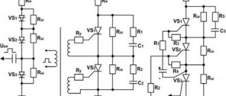
Connection diagram for starting and running capacitor
Combined circuit with two capacitors The optimal option for averaging operating characteristics is a circuit with two capacitors - starting and working. In any circuit, it is very important to connect the capacitor correctly.
When the rotor is stationary, these fields lead to the appearance of moments of equal magnitude, but differently directed. Secondly, and most importantly, the author was convinced in practice that even an extremely accurate calculation is not a guarantee of the correct operation of the engine.
The latter is smaller in size and is a launcher. The position of the contacts in the junction box of a three-phase motor. Connecting a three-phase motor according to a star scheme. The junction box of a three-phase motor with the position of jumpers for connecting according to a star scheme. When a three-phase motor is connected to a three-phase network, a current begins to flow through its windings at different times in turn, creating a rotating magnetic field, which interacts with the rotor, causing it to rotate. Place one or an entire assembly of several samples with different denominations - whatever is more convenient for you.
Ideally, they should be equal to each other; if there are small differences of 30 percent, then this is not ideal, but still good. If possible, it is better to use it, since the engine will lose less power, and the voltage across the windings will be equal to V everywhere.
Connection diagrams
In this case, to connect the motor according to the “triangle” scheme, it is necessary to bring the missing ends of the windings C4, C5, C6 into the box. Therefore, the power is lost almost twice, but such an engine can be used in many low-power devices. The same applies to the organization of engine reversal.
It will be more reliable this way. Edited by A. If a three-phase electric motor is connected to a single-phase network, then this rotating torque is not created.
The starting branch will be used until the motor turns around, the working branch will be used throughout the entire operation of the engine. The diagram of a single-phase electric motor is shown in Figure 1. And connect the remaining 2 ends to the Volt power supply. To achieve the maximum starting torque, a circular magnetic field is required that performs the rotation. How to connect a motor from an old washing machine through or without a capacitor
Mixed connection of conductors
Series and parallel resistance circuits can be combined in one electrical circuit if necessary. For example, it is possible to connect parallel resistors in a series circuit to another resistor or group of resistors; this type is considered combined or mixed.
In this case, the total resistance is calculated by summing the values for the parallel connection in the system and for the series connection. First, it is necessary to calculate the equivalent resistances of resistors in a series circuit, and then the elements of a parallel circuit. Serial connection is considered a priority, and circuits of this combined type are often used in household appliances and appliances.
So, by considering the types of conductor connections in electrical circuits and based on the laws of their functioning, you can fully understand the essence of the organization of circuits of most household electrical appliances. For parallel and series connections, the calculation of resistance and current is different. Knowing the principles of calculation and formulas, you can competently use each type of circuit organization to connect elements in the optimal way and with maximum efficiency.
Main Application of Capacitors
The word “capacitor” can be heard from employees of various industrial enterprises and design institutes. Having understood the principle of operation, characteristics and physical processes, let’s find out why capacitors are needed, for example, in power supply systems? In these systems, batteries are widely used during construction and reconstruction at industrial enterprises to compensate for the reactive power of the reactive power supply (unloading the network from its unwanted flows), which makes it possible to reduce electricity costs, save on cable products and deliver better quality electricity to the consumer. The optimal choice of power, method and location of connecting reactive power sources (Q) in electric power system (EPS) networks has a significant impact on the economic and technical performance indicators of EPS. There are two types of KRM: transverse and longitudinal. With transverse compensation, capacitor banks are connected to the substation busbars parallel to the load and are called shunt batteries (SHBK). With longitudinal compensation, batteries are included in the cutting of power lines and are called LPC (longitudinal compensation devices). Batteries consist of individual devices that can be connected in different ways: capacitors connected in series or in parallel. As the number of devices connected in series increases, the voltage increases. UPCs are also used to equalize loads across phases, increase the productivity and efficiency of arc and ore-thermal furnaces (when the UPC is connected through special transformers).
In equivalent circuit diagrams of power transmission lines with voltages above 110 kV, capacitive conduction to ground is indicated in the form of capacitors. The EP of the line is determined by the electrical capacitance between conductors of different phases and the capacitance formed by the phase wire and ground. Therefore, to calculate network operating modes, power transmission line parameters, and determine locations of damage to the electrical network, the properties of a capacitor are used.
How to check the quality of connection of capacitors in a circuit
The most ideal case is when we have an appropriate type of voltmeter on hand. It costs around one thousand rubles.
This is not so much, considering that together we get a device for measuring resistance, direct and alternating voltage, and currents.
The socket for measuring the capacitor (see photo on the left) consists of two narrow slots into which the legs should be inserted.
According to our observations, there is no difference which side to insert the electrolytic capacitor. Although it is better to follow the instruction manual.
Then you need to somehow mark them, or lay them out according to a diagram drawn on paper, where you can put all the numbers (by the way, this is usually done in all Chinese technology).
Then you should calculate using the formulas exactly what value should be obtained and check it with a tester. Does not work? This means that the quality of the contacts is poor - use less twisting.
CAPACITOR CONNECTIONS
If it is necessary to increase the total capacitance of the capacitors, then they are connected to each other in parallel (Fig. 9, a
). With this connection method, the total area of the plates increases compared to the plate area of each capacitor. The total capacitance of capacitors connected in parallel is equal to the sum of the capacitances of the individual capacitors and is calculated by the formula Ctot = C1 + C2 + C3+
(10)
This can be confirmed as follows.
Capacitors connected in parallel are under the same voltage, equal to U volts, and the total charge of these capacitors is equal to q coulombs. In this case, each capacitor respectively receives a charge q 1, q 2, q 3, etc. Therefore,
q total = q 1 + q 2 + q 3 +
From formula (8) it follows that the charge
qtot = Ctot U (11)
and charges q 1 = C 1 U; q 2 = C 2 U; q 3 = C 3 U.
Substituting these expressions into formula (11), we obtain:
C total U= C 1 U + C 2 U + C 3 U.
Dividing the left and right sides of this equality by the value U equal for all capacitors, after reduction we find:
C total = C 1 + C 2 + C 3
Example
. Three capacitors with a capacity C 1 = 2 μF; C 2 =0.1 µF and C 3 =0.5 µF are connected in parallel.
Calculate their total capacity.
C total = C 1 + C 2 + C 3 = 2 + 00.1 + 0.5 = 2.6 μF.
The total capacitance of capacitors having the same capacitance and connected in parallel can be calculated using the formula
Ctot = Cn, (12)
where C is the capacitance of one capacitor,
n is the number of capacitors.
Example.
Five capacitors with a capacity of 2 μF each are connected in parallel. Determine their total capacity.
C total = Cn = 2·5 = 10 μF.
Capacitors are connected in series (Fig. 9, b) when the operating voltage of the installation exceeds the voltage for which the insulation of one capacitor is designed. In this case, the right plate of the first capacitor is connected to the left plate of the second, the right plate of the second to the left plate of the third, etc. The total capacitance of the capacitors with this connection decreases. The reciprocal of the total capacitance of capacitors connected in series is equal to the sum of the reciprocals of the capacitances of individual capacitors:
This can be confirmed as follows. The total voltage on the capacitors U is the total on each capacitor U 1, U 2, U 3, then
U total = U 1 + U 2 + U 3.
From Formula (8) it follows that the voltage
U total = (14)
and the voltage
Substituting these expressions into formula (14), we obtain:
Let us divide the left and right sides of this equality by the value q and after reduction we find:
Example. Three capacitors C1=2 µF, C2=4 µF and C3=8 µF are connected in series. Determine their total capacity.
If capacitors having the same capacitance are connected in series, then their total capacitance can be calculated using the formula
Example.
Four capacitors with a capacity of 1000 pf each are connected in series. Determine their total capacity. Solution.
If two capacitors of different capacitance are connected in series, then their total capacitance can be found using the formula
Example.
Two capacitors C 1 =200 pF
and C 2 =300 pf connected in series. Calculate their total capacity.
As can be seen from the above examples, the total capacitance of capacitors connected in series is always less than the smallest capacitance included in the connection.
Capacitors are selected according to their capacitance and the operating voltage that is supplied to its plates when connected to the circuit. When the voltage exceeds the permissible value, a breakdown of the dielectric in the capacitor occurs. This voltage is called breakdown voltage. The breakdown of the dielectric is accompanied by an electrical discharge - a spark with a characteristic crackling sound. A capacitor with a broken dielectric is not suitable for use.
Each dielectric has a certain electrical strength, i.e., the ability to resist breakdown. Electrical strength (Table 2) is usually measured in (v/cm
) and is determined by the formula
where U is voltage, V
d—dielectric thickness, cm.
Many people, when assembling a particular device, often think about how to connect capacitors in a parallel or series connection. Not every denomination is produced by industry, so the task of providing a design with a bunch of containers occurs here and there. When connected in parallel, the denominations are added, and when connected in series, a more complex formula is used. There are also tuning capacitors; these are definitely included in circuits where it is necessary to provide the necessary resonant characteristics. In this case, it is also necessary to solve the above problem. The problem is that often the assembly of some kind of induction heater is literally done on your knees, there is a whole pile of iron, there are no pads at hand, and you are too lazy to solder - what to do?
Capacitor capacity
Capacitors are mainly characterized by two parameters: capacitance and operating voltage. The first describes the ability to store charge and is expressed in farads (symbol F). However, this is a very large unit, so in practice you will mostly see:
- picofarads [pF] (1 pF = 0,000,000,000,001 F),
- nanofarads [nF] (1 nF = 0.000,000.001 F),
- microfarads [µF] (1 µF = 0.000 001 F).
| The Greek letter "mi" [μ] is difficult to write on a computer, so the Latin letter [u] is often used to indicate similarity. |
Comparison of different options
| Capacity | Voltage | |
| Parallel | Increases | Doesn't change |
| Sequential | Decreases | Increases |
| Mixed | Changes | Increases |
To select a connection, you can use the following table. On the left is the type of connection of devices, on top is the properties of the device for charge condensation.
If you need to increase the capacity, then you need to use a parallel connection, and if you increase the voltage, then a serial connection. If both are required, then it will be necessary to calculate the mixed connection of capacitors in the circuit.
Capacitance
Experience shows that if you connect a capacitor in series with a light bulb and connect them to a constant voltage generator, the light bulb does not light up. This is understandable, since the capacitor plates are separated by a dielectric, and the circuit is open. When a capacitor is connected to a DC source, a short-term current pulse occurs, which will charge the capacitor to the source voltage, and then the current will stop. But if this circuit is connected to an alternating voltage source, the light bulb lights up. Alternating current is forced electromagnetic oscillations that occur under the influence of the alternating electromagnetic field of the generator. When a capacitor is connected to an alternating current circuit, its charging process lasts a quarter of a period. After reaching the amplitude value, the voltage between the plates of the capacitor decreases, and the capacitor is discharged within a quarter of the period. In the next quarter of the period, the capacitor is charged again, but the sign of the charge on its plates changes to the opposite, etc. Electrical charges do not pass through the dielectric separating the plates of the capacitor, as in a direct current circuit. But through the wires connecting the capacitor plates to the voltage source, alternating current flows to discharge and charge the capacitor. Therefore, a light bulb connected in series with a capacitor will burn continuously. If you now disconnect the capacitor, the light bulb burns brighter. Therefore, the capacitor provides resistance to alternating current, which is called capacitance
.
Let's consider a circuit (Fig. 1) consisting of a capacitor and lead wires, the resistance of which is negligible, and an alternating voltage generator.
Rice. 1
Let the voltage on the capacitor change according to the law \(~U = U_0\sin wt.\) As is known, the charge on the plates of the capacitor can be determined by the formula \(~q = CU = CU_0\sin wt.\) Current strength \(~I = q'.\) Therefore,
\(~I = -wCU_0\cos wt = wCU_0\sin(wt+\frac {\pi}2).\)
Hence \(~I=I_0\sin (wt +\frac {\pi}2),\)
where \(~I_0=wCU_o\) is the amplitude value of the current:
\(~I_0=\frac {U_0}{\frac 1{wC}}; I_0 =\frac {U_0}{X_C},\)
where \(~X_C = \frac 1{wC}.\)
Expressing the amplitude values in terms of the effective \(~I_0 = \sqrt2 I \) and \(~U_0 = \sqrt2 U,\) we obtain \(~I= \frac U{X_C}, \) i.e. the effective value of the current is related to the effective value of the voltage on the capacitor in the same way as the current and voltage in the DC circuit section are related according to Ohm's law. This allows us to consider the value of X
c as the capacitor's resistance to alternating current:
\(~X_C = \frac 1{wC}\) - capacitive reactance.
The SI unit of capacitance is the ohm (Ω).
As can be seen from the formula obtained above, if only capacitance is included in the circuit, current fluctuations in this circuit are ahead in phase of voltage fluctuations on the capacitor by \(~\frac {\pi}2,\), which is shown in the graph and in the vector diagram (Fig. 2).
Rice. 2
Instantaneous power
\(~P=IU = I_0\sin (wt +\frac {\pi}2)U_0\sin wt = I_0U_0\sin wt \cos wt =\frac {I_0U_0}2 \sin 2wt,\)
those. power periodically changes with double frequency, and the average power value is for the period \(\mathcal h P \mathcal i =0.\) since \(~\mathcal h \sin 2wt \mathcal i = 0.\) The first and third quarter of the period when the capacitor is charging, it receives energy from the generator, and the second and fourth quarter of the period, when the capacitor is discharging, it gives energy to the generator.
Thus, just like active resistance, capacitive reactance limits the current in a circuit, but unlike active resistance, capacitive reactance does not convert electrical energy irreversibly into other forms of energy.