In lamps and flashlights, two circuits are used - serial and parallel connection of LEDs. These schemes have a lot of variations and combined options, each of them has its own advantages and disadvantages.
To understand which connection diagram is better, you need to find out what the current-voltage characteristic is and what it is like for an LED.
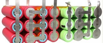
The photo shows an LED matrix for connecting to a 220V network
Basic theoretical issues
Current-voltage characteristic (abbr. VAC) is a graph displaying the dependence of the amount of current flowing through any device on the voltage applied to it. A simple and very capacious characteristic for the analysis of nonlinear components. With its help, you can select operating modes and determine the characteristics of the power source for the device.
Take a look at an example of linear and nonlinear I-V curves.
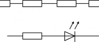
Graph number 1 in the figure displays the linear dependence of current on voltage, which is what all resistive devices have, for example:
- Incandescent lamp;
- heater;
- resistor (resistance);
Graph number 2 is the current-voltage characteristic characteristic of pn junctions of diodes, transistors and diodes.
Top 3 best manufacturers of 220 V LED strips
It is difficult to name the best manufacturers, since there are simply no general criteria for evaluating such devices. Among the worthy companies there are American, European, and Chinese companies. The best of them include the following brands:
- CREE. This is an American company that has been operating since 1987, i.e. almost since the advent of LED lamps. Today, CREE produces a wide range of LED devices, and strips occupy a significant part among them;
- OSRAM. This is a well-known company that is one of the European leaders in the production of lighting equipment and, in particular, semiconductor light bulbs. The company's products are noticeably expensive, but the quality of their lamps is quite consistent with price demands;
- ERA. The Russian company, created in 2004, presents quite competitive products, which are highly appreciated by users both in our country and in neighboring republics. An attractive feature of this brand’s LED strips is their low price with quite decent quality, which confirms the steady demand.
The choice of tape should be made primarily based on technical characteristics. The name of the company serves only as a guarantee of compliance with the declared and actual parameters of the product.
Learn more about how diodes work
Which LED connection should I choose: series or parallel? This greatly depends on the operating conditions and the power source, as well as the voltage and current stabilization system. To make the right choice, you need to consider both options.
Initially, we were talking about the current-voltage characteristic for a reason; let’s consider in detail its form for LED devices.
Please note that in the voltage range lower than 2.5V, very little or no current flows through the LED. Having overcome the level of 2.5 volts, current begins to flow through the diode and it lights up in the area from 2.5 to 3 volts. After this level, the current begins to increase rapidly.
For 5 mm white light diodes, the operating current is 20 mA at 3V, and at 3.5 volts the current will be 80 mA, which is four times higher than the nominal value.
Although the brightness of the diode depends on the current flowing through it, at excessively high values the LED does not glow much brighter than at nominal value. Therefore, you should not experiment with high indicators - your diodes will simply burn out.
Voltage values may vary depending on the types and design of LEDs, this is influenced by their number in one package, color, and even the material that was chosen as the basis of the chip.
Why do blocks of several parallel diodes work so well?
The MOSFET's on-channel resistance has a sharply positive temperature coefficient, which ensures that the hotter MOSFET has a higher resistance than the cooler one, causing a slightly higher current to flow through it. Therefore, for two such MOSFETs, a thermal balance is established that corresponds to the current balance. This thermal balance is guaranteed by proper PCB layout. In general, dense placement of components is justified. But if there is another device on the board that dissipates a lot of heat, then the thermal gradient it causes changes the balance of current distribution for parallel-connected ideal diodes.
How to connect correctly?
When connecting LEDs in parallel, you need to use a limiting resistor for each diode, as shown in the figure below. This makes it possible to set the current for each of the elements of the electrical circuit.
LED Parallel Connection Diagram
Below is a diagram of NOT correctly connecting a resistor to a circuit.
This is not the right way to connect
When connecting LEDs and any other consumers in parallel, the voltage at their terminals will be equal. On the one hand, this is good, but not for diodes. Each LED, even a set taken from the same batch, has a small technological variation in parameters. The voltage required to achieve the rated current may vary slightly within tenths of a volt.
Above you saw the current-voltage characteristic of the device and you can easily conclude that a slight excess of the rated voltage leads to an avalanche-like increase in current and overheating. Some suggest excluding the resistor from this circuit; this connection of LEDs is the worst!
The total current in the circuit is equal to the sum of the currents in each of the branches of the parallel circuit. If you choose how to connect LEDs to operate in a circuit with high voltage (6 volts or more), it is better to use a series connection.
Easy replacement for RGB LED control without PWM circuit
This type of control has proven itself well in the illumination of car dashboards and any backlights without the use of PWM controllers.
The LED supply current is calculated based on ten elements per channel and is 12 mA, which is three times less than the rated current for bright LEDs. This increases the service life of the elements with good brightness. Current-limiting resistors were selected on the basis that the number of elements is at least 10 and they are identical in type. If you use LEDs of a different type or quantity, you should recalculate the current and the value of resistors R4.1 - R4.3. The drop across one element is 3 volts, so to shift the base voltage, additional resistors R3.1 - R3.3 were introduced into the amplifier circuit, which compensate for the dead band of the potentiometers. This method, scheme is borrowed from.
This, in principle, is the whole “cunning” technology for controlling RGB LEDs. Nothing complicated. But again, these schemes, methods (and not only) are needed for those “specifically obsessed” with radio electronics or engineers. For ordinary people, it is enough to purchase all kinds of ready-made controllers for controlling RGB. This can be easily done on the Aliexpress site. Cheap and buy the same thing as in local stores, but with inflated prices from resellers. With this I say goodbye to you and see you again.)
Online calculator for calculating a resistor
| Connection type: | |
| Supply voltage: | Volt |
| LED forward voltage: | Volt |
| Current through LED: | Milliamp |
| Number of LEDs: | PC. |
| Results: | |
| Exact resistor value: | Ohm |
| Standard resistor value: | Ohm |
| Minimum resistor power: | Watt |
| Total power consumption: | Watt |
Increasing the generator charging voltage
The topic may not be new, but it is still relevant today. There are many ways to increase the battery charging voltage described online. I don’t claim authorship, but I haven’t seen this method and I want to share my experience in remaking the generator “tablet”.
As you know, in winter, when consumers are turned on, the voltage of the on-board network drops to 12.8-13.5 V and, accordingly, undercharges the battery. I went, as I believe, along the least path of resistance, by including a voltage booster in the electronic circuit of the stabilizer (tablet).
Zener diode VD1 ensures stabilization of half the excitation voltage of the generator, so when a diode is added, an additional voltage drop occurs on it, which ensures that the generator excitation voltage is turned off at a higher voltage.
Well, now how to implement all this in practice.
Take the relay regulator, drill out the rivets and remove the cover.
Carefully remove the compadum from the board, using a screwdriver or a stiff brush. The zener diode we need (for those who are not entirely familiar with radio engineering) is a glass cone with a strip. The strip designates “Minus”. We unsolder the zener diode and solder a minus to minus diode to it. We solder the resulting assembly back.
This is what happened. Next, fill everything with sealant and close the lid. Can be duplicated with screws.
When using a 1n004 diode, the charging voltage without load is 14.8 volts. With all consumers turned on, 13.8 -14.2 V.
Author; Alexander Rodin Shchelkovo, Moscow region
As you know, additional equipment is often installed on a car, which draws additional voltage from the on-board network. Thus, the voltage indicator on a VAZ-2114 can drop to a critical level of 11 volts . If you also install additional air conditioning or heated seats, this may result in the starter not having enough power to start the engine. How to fix the problem? Make sure that the voltage in the on-board network increases.
Video about increasing the voltage in the on-board network on VAZ cars:
The video will tell you how to increase the voltage of the generator and on-board network with your own hands, and will also tell you about some of the nuances and subtleties of the process
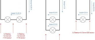
Connection options
To make a serial connection of 220V LEDs, use the diagram below.
In this case, capacitor C1 limits the current to a greater extent; it plays the role of reactance. We wrote more about calculating a capacitor in the article . To obtain the required capacitance value of the capacitor, use the online calculator:
This way you can connect even one LED.
If you want to build a 100 volt DC LED series circuit, you need to include about 30 LEDs in the circuit. Then the required voltage will be about 90 volts. Calculate the resistor using the formula in the previous sections of the article.
A capacitor is needed to smooth out current ripples, a resistor in parallel is needed to discharge the capacitor after turning off the device, for safety reasons. If the power source is sufficiently stabilized, they can be excluded.
Connecting an LED to a 220 V network using the example of a backlit switch
Nowadays you won’t surprise anyone with a switch with integrated LED lighting. Having disassembled it and figured it out, we will get another way, thanks to which we can connect any LED to a 220 V network.
All illuminated switches use a resistor rated at least 20 kOhm. The current in this case is limited to about 1A. When connected to the network, this LED will glow. At night it can be easily distinguished on the wall. The reverse current in this case will be very small and will not damage the semiconductor. In principle, such a circuit also has a right to exist, but the light from such a diode will still be negligibly small. And whether the game is worth the candle is not clear.
Alternative connection type
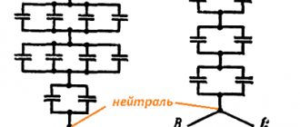
Series-parallel connection of LEDs - found in floodlights and other powerful lamps operating on both direct and alternating voltage.
As you can see, the matrix is divided into branches, each of which has a current-limiting resistor. A specific copy is intended to replace the standard courtesy lamp in the car interior. If one diode fails, one circuit will stop lighting, and the remaining circuits will continue to glow.
If you can't decide whether to connect LEDs in series or parallel, there is an alternative option - a hybrid connection. At first glance, it is not clear what the point is.
The hybrid version takes advantage of the serial and parallel connection of LEDs. The circuit will work fully even if one of the elements in the circuit burns out, while at the same time the remaining elements will not experience overload. The voltage on each segment will be limited to the LED with the lowest drop.
To assemble the lamp correctly, and to ensure that the LEDs work for a long time and do not overheat, you need to decide how to connect the LEDs - in series or in parallel. You have become familiar with the strengths and weaknesses of each option. Thanks to the knowledge gained, you can repair an LED lamp or spotlight.
Please rate the article. We tried our best:)
Did you like the article? Tell us about her! You will help us a lot :)
Scope of application
The peculiarities of the emission spectrum do not prevent dual-illumination LEDs from finding a field of application.
LED indicators based on two-color diodes are used:
- in advertising;
- in signaling systems (traffic lights, flashing lights, signs, electronic displays);
- in electric motors (to determine the direction of rotation);
- when decorating premises;
- in phones, tablets, cameras;
- in charging various batteries;
- for car tuning.
In everyday life, you can make a garland from two-color LEDs. One color lights up during the positive half-cycle, the second - during the negative half-cycle.
Final voltage measurements and results
After the installation was completed and the entire electrical circuit was working, voltage measurements were made at idle speed of the running engine. The results surpassed themselves; the voltage in the entire electrical circuit increased.
Let's consider a table of the results of the measurements obtained:
| Load | Voltage up to | Voltage after |
| without load | 14.2 | 14.45 |
| +dimensions | 13.8 | 14.45 |
| +PTF | 13.7 | 14.4 |
| +neighbor | 13.6 | 14.35 |
| +heater | 13.5 | 14.3 |
| +Fan | 13.4 | 14.2 |
| +far | 13.2 | 14.1 |
| + heating | 13.1 | 14.0 |
| +heater max | 12.9 | 13.95 |