A resistor is a device that has a stable, stable resistance value. This allows you to adjust parameters in any part of the electrical circuit. There are various types of connections, including mixed connections of resistors. The use of one or another method in a specific circuit directly affects the voltage drop and current distribution in the circuit. The mixed connection option consists of serial and parallel connection of active resistances. Therefore, you need to consider these two types of connections first to understand how other circuits work.
Serial connection
A sequential connection diagram involves the arrangement of resistors in the circuit in such a way that the end of the first element is connected to the beginning of the second, and the end of the second to the beginning of the third, etc. That is, all resistors follow each other in turn. The current strength in a series connection will be the same in each element. In the form of a formula, it looks like this: Itot = I1 = I2, where Itot is the total current of the circuit, I1 and I2 correspond to the currents of the 1st and 2nd resistor.
In accordance with Ohm's law, the voltage of the power source will be equal to the sum of the voltage drops across each resistor: Utot = U1 + U2 = I1r1 + I2r2, in which Utot is the voltage of the power source or the network itself; U1 and U2 – the value of the voltage drops across the 1st and 2nd resistors; r1 and r2 are the resistances of the 1st and 2nd resistors. Since the currents in any section of the circuit have the same value, the formula takes the form: Utot = I(r1 + r2).
Thus, we can conclude that with a series circuit of resistors, the electric current flowing through each of them is equal to the total current value in the entire circuit. The voltage across each resistor will be different, but their total sum will be a value equal to the total voltage of the entire electrical circuit. The total resistance of the circuit will also be equal to the sum of the resistances of each resistor included in this circuit.
Mixed connection of passive elements. Rolling method.
A mixed combination of elements is called all possible
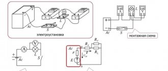
combinations of serial and parallel connections. Such a chain may have a different number of nodes and branches. One example of a mixed connection is shown in the diagram (Fig. 1.3, a).
a) b)
V)
Fig. 1.3 Scheme of mixed connection of elements (a) and its equivalent circuits (b, c)
To calculate such a circuit, it is necessary to first determine the equivalent resistances of those parts of the circuit that are only a series or only a parallel connection. In the proposed circuit, elements R 1
and
R 2
are connected to each other in series, and elements
R 3
and
R 4
are connected in parallel.
the
previously given relationships (1.7) and (1.13), you can replace R1
and
R2
with equivalent resistance
R12 ,
and elements
R3 and
R4
with equivalent resistance
R34 :
R12 = R1+R2 (1.18) R34 = ( 1.19 )
As a result of such an equivalent replacement, the circuit shown in Fig. 1.3 (b) will be obtained, in which elements R12 and R34 are connected in series. For this circuit the equivalent resistance is
Req = R12 + R34 (1.20) As a result of such an equivalent replacement, we obtain the circuit shown in Fig. 1.3 (c). Let us determine the current flowing in this circuit:
(1.21) This is the current of the power source and the current in the elements R 1
and R2 of the real circuit. Let's find the voltages on a section of the circuit with resistance R12 and on a section of the circuit with resistance R34:
U 12 = I R 12 _
;
U 34 = I R 34 1.22
)
Currents I3 and I4 can be found using Ohm's law:
(1.23) To check the correctness of the calculation of the mixed connection circuit of elements, you can use Kirchhoff’s 1st and 2nd laws, as well as the power balance law. The following relations must be satisfied:
I = I3 + I4 ; Uist = U12 + U34; Rist=ΣРpr= Р1 + Р2 + Р3 + Р4
Here P1 = ·
R1;
Р2 = ·
R2 ;
Р3 = ·
R3 ;
Р4 = ·
R4 .
In a similar way, you can calculate other, more complex electrical circuit diagrams with a mixed connection of elements.
There are other schemes of equivalent transformations, since not all schemes are reduced to a combination of series and parallel connected elements. Such schemes will be discussed in the next subsection.
The folding method is used for circuits with a mixed connection of consumers, that is, when there are sections with serial and parallel connections of consumers.
Parameters of the circuit in parallel connection
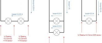
A parallel connection is the connection of the initial outputs of two or more resistors at a single point, and the ends of the same elements at another common point. Thus, each resistor is actually connected directly to the power source.
As a result, the voltage of each resistor will be the same as the total voltage of the circuit: Utotal = U1 = U2. In turn, the value of the currents will be different on each resistor, their distribution becomes directly proportional to the resistance of these resistors. That is, as the resistance increases, the current decreases, and the total current becomes equal to the sum of the currents passing through each element. The formula for this position is as follows: Itot = I1 + I2.
To calculate the total resistance, the formula is used: . It is used when there are only two resistances in the circuit. In cases where three or more resistances are connected in the circuit, another formula is used:
Thus, the value of the total resistance of the electrical circuit will be less than the minimum resistance of one of the resistors connected in parallel to this circuit. Each element receives a voltage that is the same as the voltage of the electricity source. The current distribution will be directly proportional to the resistance of the resistors. The value of the total resistance of resistors connected in parallel should not exceed the minimum resistance of any element.
Read also: What quantities determine the potential energy of a stretched spring
Mixed connection and complex electrical circuits
A common phenomenon in electrical circuits is a mixed type connection (that is, a combination of parallel and serial connections).
If, for example, you take 3 devices, then two mixed connection options will be possible. In the first case, we observe the connection of two devices in parallel with a third connected to them in series.
With a larger number of devices, mixed connection circuits will be more complex. Sometimes there are also complicated circuits containing several EMF sources.
Various techniques are used to calculate complex circuits. The most common method is one based on the application of Kirchhoff's second law. In the most general format, the law is formulated as follows: in any closed circuit, the algebraic sum of the EMF will be equivalent to the sum of the voltage drops of the same type.
The algebraic sum is taken for the reason that EMFs acting counter-actingly in relation to each other, or created by oppositely directed voltage currents, will have different signs.
Finished works on a similar topic
When calculating a complex circuit, in most examples the resistance of individual sections of the circuit and the emf of the included sources are known. To find currents, one should (based on Kirchhoff’s second law) create equations (for closed circuits) in which currents will be considered unknown quantities.
To such equations are also added equations for branch points, compiled according to the principle of Kirchhoff’s first law. When solving such a system of equations, the currents are determined. In the case of more complex circuits, such a method will be quite cumbersome, due to the presence of a large number of unknowns.
Serial and parallel connection: formulas for finding current, total resistance, voltage
When developing electrical circuits, series and parallel connections of conductors are used. The ability to analyze (both quantitatively and qualitatively) and calculate such circuits is a basic principle of electrical engineering knowledge.
Expert opinion
It-Technology, Electrical power and electronics specialist
Ask questions to the “Specialist for modernization of energy generation systems”
Total circuit resistance - definition, rules, tasks A parallel connection is a connection of sources in which the inputs of all devices are in some places and the outputs in others. Ask, I'm in touch!
Mixed resistor connection diagram
The mixed connection circuit has the properties of series and parallel connection circuits of resistors. In this case, the elements are partially connected in series, and the other part is connected in parallel. In the diagram shown, resistors R1 and R2 are connected in series, and resistor R3 is connected in parallel with them. In turn, resistor R4 is connected in series with the previous group of resistors R1, R2 and R3.
Calculating the resistance for such a circuit is fraught with certain difficulties. In order to perform calculations correctly, the conversion method is used. It consists in the sequential transformation of a complex chain into a simple chain in several stages.
If we again use the presented circuit as an example, then at the very beginning the resistance R12 of resistors R1 and R2 connected in series is determined: R12 = R1 + R2. Next, you need to determine the resistance of resistors R123 connected in parallel using the following formula: R123=R12R3/(R12+R3) = (R1+R2)R3/(R1+R2+R3). At the last stage, the equivalent resistance of the entire circuit is calculated by summing the obtained data R123 and the resistance R4 connected in series with it: Rec = R123 + R4 = (R1 + R2) R3 / (R1 + R2 + R3) + R4.
In conclusion, it should be noted that a mixed connection of resistors has the positive and negative qualities of a series and parallel connection. This property is successfully used in practice in electrical circuits.
topological concepts, elements, equivalent circuit
2.Ohm's and Kirchhoff's laws for DC circuits
3.Serial, parallel and mixed connection of consumers
Series, parallel and mixed connections of resistors. A significant number of receivers included in an electrical circuit (electric lamps, electric heating devices, etc.) can be considered as some elements having a certain resistance. This circumstance gives us the opportunity, when drawing up and studying electrical circuits, to replace specific receivers with resistors with certain resistances. There are the following methods of connecting resistors (receivers of electrical energy): serial, parallel and mixed.
Series connection of resistors. When several resistors are connected in series, the end of the first resistor is connected to the beginning of the second, the end of the second to the beginning of the third, etc. With this connection, the same current I passes through all elements of the series circuit. The voltage U at the source terminals is equal to the sum of the voltages at each from series-connected resistors.
Parallel connection of resistors. When several receivers are connected in parallel, they are connected between two points of the electrical circuit, forming parallel branches.
When connected in parallel, the same voltage U is applied to all resistors. Therefore, according to Ohm’s law:
I1=U/R1; I2=U/R2; I3=U/R3.
Current in the unbranched part of the circuit according to Kirchhoff’s first law I = I1+I2+I3,
Mixed connection of resistors. A mixed connection is a connection in which some of the resistors are connected in series, and some in parallel. For example, in the diagram of Fig. 27, and there are two series-connected resistors with resistances R1 and R2, a resistor with resistance R3 is connected in parallel with them, and a resistor with resistance R4 is connected in series with a group of resistors with resistances R1, R2 and R3.
4.Calculation of a DC circuit using the methods of loop currents and nodal potentials
Loop current method. It is based on Kirchhoff's 2nd law. The essence of the method is to maintain fictitious loop currents and calculate them.
1. Determination of the number of equations: y=v-vi.t-(n-1).
B is the number of branches, v.t is the current source, n is the number of nodes.
2. We compose equations for unknown loop currents in general form.
3. Determine the unknown coefficients of the left and right sides (E and R).
4.Substituting the coefficients, we solve the equations and find the circuit currents.
5. We determine the currents in the branches through the loop currents.
Method of nodal potentials. It is based on Kirchhoff's 1st law. We determine the potentials of the circuit nodes, followed by the determination of the currents in the branches, using Ohm's law for sections of the circuit.
1.Preparation of the diagram. Let's designate the nodes. The potential of one of them is taken to be 0.
2. We compose potential equations in general form:
Phi1*g11 + Phi2*g12 = I11 – for the first node
Phi1g21 + Phi*g22 = I22 – for the second node
3. Determine the unknown conductivities gmn – the sum of the conductivities of the branches approaching node n.
4. Substituting, solving the equations, we find phi1 and phi2.
5. We arbitrarily select the directions of the currents and, using Ohm’s law for the circuit section, we determine these currents: In = (phiX-phiY+En)/Rn.
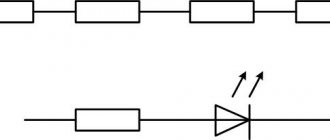
SERIES CONNECTION OF RESISTORS
This is a connection in which all elements go one after another without branches.
Properties of a serial connection
1. The current in all resistors is the same - I 1 = I 2 = I 3;
2. The total voltage of the circuit is equal to the sum of the voltages on all resistors - U = U 1 + U 2 + U 3 ;
3. The resistance in relation to the input terminals is called the input resistance and is equal to the sum of the resistances of the sections - Rin = R1 + R2 + R3;
4. The greater the resistance of the section, the more the voltage drops across it.
PARALLEL CONNECTION OF RESISTORS
This is a connection in which all the beginnings of the elements are connected to one point, and all the ends to another, and voltage is applied to these points.
Properties of parallel resistor connection:
1. The total voltage of the circuit is equal to the voltage in each section -
U = U 1 = U 2 = U 3
2. The total current of the circuit is equal to the sum of the currents in all sections - I = I 1 + I 2 + I 3
3. To find the input resistance, first calculate the reciprocal of the input resistance
– conductivity (G)
The total conductivity of the circuit is equal to the sum of the conductivities in each section.
G = G 1 + G 2 + G 3
4. The greater the resistance of the section, the less the current flowing through it.
When connecting two resistors in parallel, the input resistance formula can be converted
1.
2. If the total current is known, then you can find the branch current by multiplying the total current by the resistance of the opposite branch and dividing by the sum of the resistances; .
Exercise
Answer options
1. When resistors are connected in series, are the voltages of the sections proportional to the resistances of these sections?
2. When resistors are connected in parallel, are the currents of the branches proportional to the resistances of these branches?
3.Indicate which of the given mathematical expressions cannot be used to calculate the input resistance of two parallel-connected resistors.
A) ; b);
V) ; G)