There are two phases in the socket at once. How can this be?
In the normal state of the electrical wiring in the outlet, one contact has 220 Volts, and the second is not energized.
This is ideal. Sometimes the indicator can show two phases in the socket at the same time. To a novice electrician or amateur, such a situation may seem absurd, but it is reality. In some violations, this is exactly the picture observed.
Single-phase current of 230 volts is supplied to residential buildings. According to this diagram, it turns out that two phases cannot appear in the socket. In older buildings, the wiring is made of two-core cables. Along one line (phase) the current goes to the consumer, and along the other (zero) it returns.
With such a circuit, the reasons for the appearance of two phases in the plug connector may be different. New houses have grounding, which can cause accidents only if there is unqualified intervention in the electrical circuit of the home.
How to protect yourself?
Having learned about the danger posed by the loss of zero, we suggest considering options for protecting against this phenomenon:
- You need to start with proper installation of electrical wiring. If it is planned to use a three-phase power supply circuit to power the facility, then it must be calculated in such a way as to minimize the likelihood of phase imbalance. That is, it is necessary to systematically distribute the load on each line.
- Devices that balance the load on each phase should be used in network management. Moreover, ideally, this work should be carried out without the involvement of operators, that is, it should be performed automatically when the zero is broken.
- It should be possible to quickly change the consumer connection scheme. This allows adjustments to be made if at the design stage the load on each section was not properly taken into account or the power consumption increased due to the commissioning of new facilities. That is, if a critical situation arises, it must be possible to change the power. An example is when an apartment building is transferred to a line with a higher load to “dilute” the phase imbalance that occurs when the zero is broken.
In the above options, we considered protection against distortions on a global scale; the end user can provide the required level of protection much easier. To do this, it is enough to install a voltage control relay, in which you indicate the permissible minimum and maximum levels. As a rule, this is ±10% of normal.
Break of zero at the input
If the zero wire in the incoming cable is disconnected, the lights in the apartment will go out and electrical appliances will stop. Checking with an indicator will show the presence of a phase on each contact of the socket. The classic question arises: “Who is to blame and what to do?”
In the absence of zero, the current searches for a free line. If the lamp is turned on, it does not light, but the phase passes through the filament to the neutral wire, then to the bus, and from there to the neutral line of sockets. The phase can also come from a device connected to any plug connector in the apartment. Now there is a phase on each socket of the socket. The indicator emits a light signal when each contact is touched.
A multimeter helps to easily clarify the situation. If you measure the voltage difference between two phases, the device will show a zero value. It is clear that this is the same phase. It is enough to turn off the lamps and disconnect the devices from the sockets and the second phase in the socket will disappear, because the voltage and neutral supply lines do not have other connection points.
It is necessary to restore the incoming zero line. It is possible that the wire has simply become disconnected from the bus. This problem can be dealt with even at home. De-energize the apartment by opening the phase input and check the absence of voltage. Insert the neutral lead into the terminal and tighten the screw.
Why is zero electrocuted?
When touching live elements, a person is exposed to a potential difference between the point of contact and the ground, so under normal conditions a zero cannot be shocked.
The presence of significant potential at the neutral terminal indicates an emergency situation. There are several reasons why voltage appears on the neutral wire.
Zero break in the apartment
The most common reason that the indicator lights up at zero is a break or poor contact at the connection in the neutral conductor circuit. In the event that a break occurs in the single-phase electrical wiring in the apartment, the voltage reaches the zero terminal through the electrical appliances plugged into the socket; the same phase will be present on both contacts.
Therefore, there will be no potential difference between them, and when measuring voltage with a voltmeter, the device will show its absence.
This situation most often occurs when carrying out repair work indoors and does not lead to failure of electrical appliances. In addition, a zero break can occur when a circuit breaker fails.
Broken neutral in the power cable
It is much worse if the neutral wire is broken in the area between the floor panel and the point where the PEN conductor is divided into PE and N or the connection of the neutral to the supply transformer. In this case, the equalizing current stops flowing through the cable and voltage appears at this terminal.
Its value, as well as the voltage in the outlet, depends on the uniform distribution of the load across the phases and can reach 220 and 380V, respectively. In this case, you must immediately turn off the input circuit breaker and contact the power supply company.
Phase short circuit to zero
Another reason why the neutral wire shows voltage may be a short circuit between the phase and neutral conductors, followed by burnout of the neutral. This most often occurs in overhead power lines. At the same time, another phase appears at the zero terminal in the socket and the voltage in the network will be 380V.
The necessary actions are the same as in the previous situation - turn off the power to the line and contact the appropriate services.
Induced voltage
Induced voltage, or pickup, can appear on disconnected wires of a long-distance power line laid near an active high-voltage line.
In this case, the wires are like windings of a transformer, and a voltage sufficient to cause an electric shock may appear on the disconnected line. The current will be small, but sufficient to cause discomfort. Therefore, before working on disconnected cables, it is necessary to check whether there is voltage on the neutral wire.
| Reference! A person feels 0.01A of alternating current flowing through the body, and 0.1A is fatal. |
Phase imbalance
In the private sector, rural areas and in detached buildings located at a considerable distance from the transformer substation, there may be another reason why the zero is electrocuted. This is due to the voltage drop in the neutral conductor when equalizing currents flow through it.
Most of the overhead lines were laid back in Soviet times, when the most powerful electrical appliance was an iron, and a 5A fuse was installed at the entrance to the apartment.
Now many houses have air conditioners, electric boilers, and heating of private houses is carried out using electric heating. This leads to an increase in current in the wires and, as a consequence, equalizing currents.
In this case, a voltage drop occurs in the wires, as a result of which the phase voltage can drop to 170-180V, and on the neutral conductor it can reach 20-30V.
It is impossible to eliminate such a malfunction; for this it is necessary to change the power lines, so in such situations it is recommended to install a stabilizer.
| Important! Low voltage can also lead to failure of electrical appliances, especially those with electric motors - refrigerators, washing machines or air conditioners. |
Breakage of the neutral wire in the junction box or in the wall
Sometimes a zero break occurs in the junction box. In this case, part of the apartment's wiring is functioning normally, but the line connected to this box is inoperative. It is enough to find where the zero broke off or burned out and restore the connection.
It happens that two phases appear in the plug connector due to damage to the neutral wire inside the wall. The cause of the malfunction is negligence when drilling holes. If you break the insulation by breaking through the wire, the neutral conductor will be welded to the phase conductor. In this case, there will also be two phases in the outlet. It is necessary to lay a new line or open the damaged area and repair the wiring.
Features of the neutral wire
The neutral wire prevents undesirable situations during emergency operation. Without it, in the event of a phase short circuit of two phases, the voltage in the third phase will instantly increase by √3 times. This will have a detrimental effect on the equipment that powers this source. If there is a zero in this situation, the voltage will not change.
If one of the phases in a three-phase three-wire system (without zero) breaks, the voltage on the two remaining phases will decrease. They will be connected in series, and with this type of connection the voltage is distributed among consumers depending on their resistance.
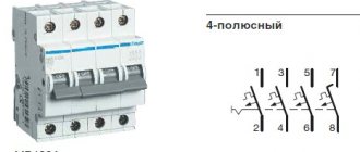
If one of the phases in a three-phase four-wire system breaks , the voltage in the two remaining phases will not change its value.
Fuses are not installed in the neutral wire due to its great importance, because its breakage is undesirable
Since most of the time electrical installations operate, the current in this wire is either zero or insignificant, there is no point in making it the same cross-section as the phase wire cross-section. Most often, for reasons of economy, it has a smaller cross-section of the conductor than the cross-section of the conductors of the phases in one electrical installation. If the protective wire is not combined with the neutral wire, its cross-section is half that of the phase wire.
Induced currents
Everything works fine, but the indicator detects voltage on each pin of the plug connector. Moreover: the device shows two phases in the socket when the power supply to the entire apartment is turned off. This completely unrealistic situation can happen if a high-voltage power line runs near your home.
The information posted on this page is for informational purposes only. We recommend that all electrical work be carried out by a professional electrician.
This is the so-called pickup or, to put it more correctly, induced voltage. Even experienced electricians can get confused here. Work in this case is associated with a high risk of electric shock, so only professionals should perform it.
What's new in the VK SamElectric.ru group?
Subscribe and read the article further:
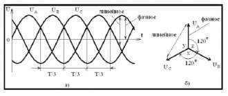
Voltages in a three-phase system
Let's look at this issue again, only from the other side.
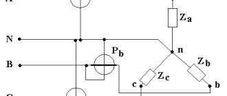
This is what a simplified diagram of the power supply to the floor panel looks like:
Power supply system, without zero break. Three apartments are designated by resistors.
Phase wires L1, L2, L3, on which there is a voltage of 220V in relation to the neutral wire N, are marked in red because they pose a danger. The PE grounding is shown below; its wire is connected in the switchgear at the entrance to the building with the neutral.
For more details, I once again urge you to read my article about grounding systems, link at the beginning.
About the presence of a second phase in the socket
The phase indication on two contacts of a plug socket in most cases does not indicate the presence of two phases. To verify this, it is enough to measure the voltage between the contacts with a multimeter. Although the possibility of the appearance of interphase voltage cannot be completely excluded, this is a characteristic sign of a break in the main zero with subsequent phase displacement. We propose to consider all possible options, first we list them:
- Zero break at the input.
- Loss of electrical contact between one of the lines and the neutral bus in the distribution box.
- Zero break followed by short circuit to phase.
- Damage to the main neutral core with subsequent phase displacement.
It is typical that in the first three options, if you connect the device to a problematic outlet, it simply will not function. As for the latter case, when the phases are shifted, there is a high probability of failure of all electrical devices connected to the network. What this is connected with will be discussed further.
Break of zero at the input
One of the characteristic malfunctions of old electrical wiring is the burnout of the zero on the zero bus (see A in Fig. 3) or the loss of electrical contact on the input circuit breaker (B). In most cases, the reason lies in the use of aluminum wires, the plasticity of which causes the contact connections to weaken. Violation of the quality of the electrical contact leads to an increase in its transition resistance, resulting in wire burnout. Note that problems can also arise with copper cables if the wire connections are not securely connected.
Figure 3. Typical problem areas: zero bus (A) and input circuit breaker (B)
If the neutral wire on the input circuit breaker in the apartment is damaged, not one of the household consumers will work. But at the same time, if at least one electrical appliance is connected to the network, a phase potential will be established on all neutral conductors (see A in Fig. 4).
Figure 4. Examples of zero breaks
If in this situation you try to measure the voltage with a probe on the contacts of any socket, it will show the presence of a phase on each of them. By connecting a voltmeter, you will make sure that the potential difference between the plug connectors is zero.
To make sure that the described malfunction occurs, you should disconnect all consumers, including lighting and heating devices, from the household power supply. Once you do this, only one phase will be induced in the sockets.
The malfunction can be eliminated by restoring the electrical contact at the input. To do this, check the AB terminals and the reliability of the connections to the zero bus.
A brief excursion into theory
When voltage is applied to a household consumer, an electric current flows through it in a closed circuit. If the circuit is open, for example, by a chandelier switch embedded in a phase wire, then there will be no glow.
In this situation, the phase potential reaches the switch, and the zero potential reaches the near contact of the base on each light bulb.
Their wires are briefly called phase and neutral. After turning on the switch, the phase potential reaches the remote contact of the light bulb and a current is formed through the resistance of the filament, which flows through the wires of a closed chain from the source of the supply transformer substation.
If you check the voltage at the remote contact of a light bulb socket with an indicator, it will indicate the phase by its glow, but there will be no glow at the near one. We conclude that the potential here is zero. Now let's look at another option.
Summarizing
In case of wiring faults caused by local loss of zero in the electrical panel or on internal wiring lines, the fault can be corrected independently. The presence of voltage at the faulty socket should be checked with an indicator; if its light is on at each contact, then most likely the zero has disappeared. To verify this, it is enough to measure the voltage between zero and phase of the plug connector.
In older TN-C systems, where only 2 wires are used for wiring, there is no wiring grounding, so such accidents can pose a serious threat to life.
Why does the indicator show voltage at zero?
The simplest device that indicates the presence of voltage is an indicator screwdriver, which shows the potential between the tip of the device and the ground. When the probe touches a live electrical element, the warning light lights up. The sensitivity of the device depends on the design of the indicator:
In a normal situation, the voltage on the neutral wire is absent or insufficient for the indicator lamp to light. If it lights up, then two options are possible:
Normal distribution of potentials in sockets
Before you figure out why there are two phases in sockets at once, you should know that a pair of supply wires are supplied to the apartment via the electrical wiring line, one of which is called phase, and the second is called zero. The potential of 220 Volts operates only on one of the socket terminals, and on the second it is zero. You can verify this by using a regular indicator screwdriver.
The presence of two potentials (phase and zero) is a prerequisite for the operation of any power supply system.
If the socket does not have one phase or for some reason the zero is missing, it will not be possible to obtain the difference between their values (220-0 = 220 Volts), called voltage. Therefore, if the zero in the sockets is missing, and you don’t know how to find it, before starting the search you should familiarize yourself with the principle of potential formation. The situation is much more complicated when, instead of zero, another phase appears on the second terminal. To eliminate this problem, you will need to understand the reasons for its occurrence.
Subscribe to the newsletter
In this case, a simple indicator screwdriver or tester will help determine the presence of voltage on the neutral wire.
How does dangerous voltage occur?
This happens for several main reasons:
Physics of the process in the event of a break or poor contact of the working zero
If the zero on the side of the transformer substation breaks, the floor panel will be left without a working zero. In this case, the current flow circuit with opposite phases feeding these apartments will be closed from one phase to another through neutral conductors, a common neutral bus in the panel, through switched on household electrical appliances, such as a refrigerator.
In this case, a voltage of up to 380 V appears at the contacts of the socket. This, in turn, is dangerous not only for humans, but also for electrical appliances that have a lower design level of insulation, and inevitably leads to their failure.
Physics of electricity in the case of phase imbalance, possible options
Phase imbalance occurs when two of the three phases are operated with an excessively high load, and the third phase is underloaded. Uneven distribution of load across phases is especially aggravated during consumption peaks at certain times during the day, for example in the evening.
In simple words, an asymmetry of currents and voltages occurs in a 3-phase system, which leads to the appearance of potential on the neutral conductor.
Also, a deviation occurs when there is an overload in the network and due to an increase in the resistance of the neutral wire, caused by the occurrence of high transition resistances in connections (twisting, soldering, bolt clamps, etc.), including its insufficient cross-section for trouble-free operation.
Insulation damage
Indication of voltage at the working zero is possible in the event of an electric current leak due to damage to the insulation of household electrical wiring or electrical appliances. A particularly great risk exists in networks with old electrical wiring that has served its standard life, the insulation of which has irretrievably lost its dielectric properties.
What to do?
Electric current is very dangerous, so you should not experiment with solving this problem yourself. In all the described cases, it is better to contact the power supply organization or a professional electrician. In the vast majority of cases, significant measures are required to assess the condition and circuits of both power and home networks.
As a preventive measure in case of network disruptions, it is worth considering installing a voltage relay or inverter stabilizer. The voltage relay will turn off the home network when the zero line breaks, and the inverter stabilizer, in addition to shutting down, has the functionality of regulating the voltage level.
Source
Reasons for the appearance of two phases
The appearance of a phase on two wires at once can be explained by the following combination of circumstances:
- A break in the neutral wire in the input panel of a house or apartment.
- It is damaged at the input or inside the junction box.
- Contact failure in the “zero” connection in only one socket.
- Short circuit of the phase wire to the neutral conductor due to insulation damage.
To understand why the indicator shows the phase on both wires at once, the reason that caused each of these phenomena will need to be considered separately.
If there is no zero in the socket, first of all you should find the place where it disappears (break). A possible option is damage to the cable at the entrance to the house or apartment, as a result of which the “zero” will disappear in all sockets installed inside the building and in individual rooms. In addition, the contact can be broken anywhere in the electrical circuit, including at the input or inside the distribution box, which will lead to the malfunction of only a few sockets.
The second case concerns those of them that are connected within the room to this particular distribution node (that is, approximately half), and in all other installation products the normally working “zero” will remain.
If there is a fault only at the input to a specific socket, the disappearance of zero and the appearance of the second phase will be observed only in it. In order for the situation under consideration to form completely - voltage reaches the broken neutral contact - it will be necessary for the exposed phase wire to accidentally short-circuit to it.
A variation of the latter case is when the neutral wire is not broken, but the phase wire with damaged insulation is shorted to the ground contact. This will also lead to the appearance of two high potentials in this outlet at once.
Why does “zero” get electric?
Sometimes voltage can occur at the zero contact in the socket. What to do about it? We solve the problem of “breaking” zero.
The appearance of a phase at zero is a fairly common occurrence. There is nothing good about this: this should not happen. What could be the problem, what should I check in my apartment or panel? As a rule, there is nothing complicated here.
Possible consequences and danger of the appearance of two phases
When a particular outlet has 2 phases at once, you must first of all worry about what this threatens for the people using it. This situation is unacceptable for the following reasons:
- The potential difference between the socket terminals will be 220-220=0 Volts.
- The voltage will be lost and connected household appliances will not work.
- A danger arises due to the loss of the protective grounding circuit, which in old houses operates through an earthen conductor (due to the lack of a local circuit).
In this case, there is no need to talk about any protection at all; the consequences may be unacceptable to people. An ignorant electrician, believing that he touches the neutral wire (in blue insulation), may find himself under high voltage. Therefore, the regulatory documentation requires that when disassembling installation products, it is imperative to check the absence of a phase on both terminals using an indicator.
In this situation, all or only the light switches connected to this junction box will also stop working. This is explained by the fact that a phase potential will appear on the neutral wire supplied to the chandelier, connected to the corresponding contact of the socket, and the voltage difference will become zero.
Consequences of a zero break in a three-phase network
- Electricians were repairing the entrance to the entrance. And during the repair, the working zero was turned off for a few seconds. A very unpleasant thing happened: when people returned home in the evening, they discovered that their TVs, refrigerators, chargers, etc. had burned out. - something that is constantly plugged into our outlets. It's good that there hasn't been a fire yet.
- Came on call, complained - tension was floating. I measure the voltage (everything is turned off) - almost 300 volts. Then, when the incandescent lamp is turned on, the voltage drops to 70V... It turned out that a bolt had burnt out in the floor panel, which received a zero. There was a break in the zero, a phase imbalance, and voltages went wild. I replaced the bolt, restored contact, and the voltage returned to normal.
Scratch bolt. Rusty, does not leak periodically. If you change it without turning it off, 100% of the equipment in the entrance will burn out!
The neutral wire burned off from the second bolt. You can see how it fell off under tension. Before falling off, it ALMOST melted the insulation of the phase wires (vertical, red and white).
What kind of lighting do you prefer?
Built-in Chandelier
The server has not been turned on yet, perhaps the intellectual damage will be greater...
At the site of this tragedy, I installed a three-phase voltage relay Barrier, read the article at the link.
As you can see, such problems occur due to incorrect actions of “electricians” or due to spontaneous breakage (burnout) of the neutral wire in the old housing stock.
In this article I will tell you in detail why this happens and how to deal with it.
Phase imbalance in a three-phase network
First of all, you need to understand what phase and what zero , and only after that - how to find them.
Expert opinion
It-Technology, Electrical power and electronics specialist
Ask questions to the “Specialist for modernization of energy generation systems”
Zero burnout in a three-phase network: modern problems of electrical networks Short circuit of one of the phases with a working neutral by zero and failure of the circuit breaker for some reason to malfunction, a large length of the line section between the short circuit point and the circuit breaker, etc. Ask, I’m in touch!
Content:
What devices can you use to find out phase or zero?
To find the zero or phase, you can also take precise devices that are not very difficult to operate, but will help to accurately determine in which wires the zero or phase is located.
How to determine phase and zero with an indicator screwdriver
The entire internal structure of this device is assembled into a hollow body made of a material with dielectric properties.
The main part of such a screwdriver is a metal pin, which usually has a flat shape.
To reduce the risk of inadvertent contact with other conductive components in the vicinity of the test line, the exposed portion of the tip is usually small.
Important! During the test, the end of the indicator screwdriver should be considered to be in full contact. When the need arises, it is capable of performing the simplest task, for example, unscrewing the screws that secure the cover of a socket or switch
But constant use of it as a screwdriver worsens the quality of the test and negatively affects the overall condition of the device.
The metal rod that fits into the tip of the housing becomes a conductor that is connected to the structure inside the screwdriver. This electrical chip consists primarily of a strong resistor with a minimum value of 500,000 ohms. Its main purpose is to reduce the current intensity when connected to the circuit to a value that is safe for the human body.
The next element is a neon based light bulb, which emits current even at low currents. Mutual electrical contact of all circuit components is ensured by a clamping spring. The screwdriver ends with a plug. It screws into the end of the outer shell (this can be all metal or a metal “heel”). In other words, this element acts as a contact pad during the verification process.
When the contact pad of the screwdriver is touched with a finger, it “joins” the circuit. Firstly, the body itself has electrical conductivity, and secondly, it is a powerful “capacitor”. According to this principle, the process of searching for phase and zero occurs.
In the case when the screwdriver's spike is in phase and the circuit is closed, the voltage is enough to generate a current that does not harm the human body by causing the neon to ignite. In the same situation, if the test falls on the zero contact point, no glow will be emitted.
Multimeter
A multimeter is another test and measurement device that a DIYer needs to master. The price of the device is low (the cost of a fully functional model ranges from 300 to 500 rubles*). Moreover, if such a purchase is possible, it is definitely in demand, since the device is multifunctional.
A multimeter should be one of the elements of the tool “arsenal” of a good owner of a house or apartment.
Important! If the wiring consists of three channels: phase conductor, neutral wire and protective earth channel, but without a color code, or if it is unclear, or if its reliability is unknown, the elimination method can be used
Tester
How to determine the phase using a tester:
- The multimeter is getting ready for use. The black test leads are connected to the COM jack and the red test leads are connected to the voltage jack.
- The operating mode switch is placed on the section intended for measuring AC voltage (
V or ACV) and the arrow will be set to a value that is greater than the network value. In another variation it could be, for example, 500, 600 or 750 volts.
Next, the voltage is measured between the stripped conductors. In this case there can be three combinations. The first is that between phase and zero the voltage should be close to the standard voltage of 220 volts. The second is that there can be the same voltage between phase and ground. However, it is true that if the line is equipped with a current leakage protection system (residual current protective device - RCD), this protection can work properly. If there is no RCD or the leakage current is small, the voltage remains within the rated range. Third - there should be no voltage between zero and ground
This is only the last option to show that the wire that does not include the measurement is phase.
Important! After checking, the voltage must be turned off and the bare end of the wire must be insulated and marked. For example, you can stick a white tape and make an appropriate inscription on it
Where did zero come from and what does it look like?
If we consider planet Earth from the point of view of electrical engineering, then it is a spherical capacitor. It has three elements:
- The earth's surface has a negative potential.
- The ionosphere is a layer of the atmosphere that receives and partially scatters solar radiation. She has positive potential.
- A gas atmosphere that has dielectric properties and acts as a lining.
The potential difference between the plates of this global capacitor is 300 thousand volts. It decreases as it approaches the surface. So, at an altitude of 100 meters its value is 10 thousand volts.
Why do we consider the Earth's potential to be zero, because in fact it has a completely material value, albeit with a negative sign? This question is worth asking the scientists of the 18th or 19th centuries who laid the foundations of electrical engineering.
For example, the English physicist Michael Faraday. So it was more convenient for them to measure the strength of the electromagnetic field - taking the Earth as the reference point (zero). This technique is used in many branches of science. For example, in thermodynamics. In it, the temperature at which the movement of electrons in the atomic structure of any substance stops is taken as absolute zero.
This is the so-called Kelvin scale, which differs from another temperature measurement system - it was proposed by Anders Celsius - by 273 degrees with a minus sign.
So, electric zero is a conventional concept that is used in relation to any object with a negative potential. It can be obtained in three ways:
- Having joined the earth's firmament, which is why the concept of “grounding” came about.
- The crystal lattice of all metals has a negative charge of varying magnitude, which determines the degree of their electrochemical activity. Therefore, it is enough to attach to a metal object of large mass and volume. The last two conditions are mandatory, since the body must have an electrical capacity comparable to that of the Earth. This is called working ground.
- By connecting conductors with alternating current flowing through them so that at a common point the sum of their vector addition is equal to zero (the so-called star circuit), which is why it was called neutral. This is the basis of a technique called zeroing in electrical engineering.
Household electrical wiring.
Initially, electricity is generated at a power plant. Then, through the industrial power grid, it enters the transformer substation, where the voltage is converted to 380 volts. The connection of the secondary windings of the step-down transformer is made according to the “star” circuit: three contacts are connected to the common point “0”, and the remaining three are connected to terminals “A”, “B” and “C”, respectively. For clarity, a picture is provided.
The combined contacts “0” are connected to the grounding loop of the substation. Also here the zero is split into:
- Working zero (shown in blue in the picture)
- PE conductor performing a protective function (yellow-green line)
The zeros and phases of the current from the output of the step-down transformer are supplied to the distribution panel of the residential building. The resulting three-phase system is distributed across panels in the entrances. Ultimately, a phase voltage of 220 V and a PE conductor, which performs a protective function, enters the apartment.
So, what is current nophase? A zero is a current conductor connected to the ground loop of a step-down transformer and serves to create a load from the current phase connected to the opposite end of the transformer winding. In addition, there is a so-called “protective zero” - this is the PE contact described earlier. It serves to drain current when a technical malfunction occurs in the circuit.
This method of connecting residential buildings to the city power grid has been proven for decades, but it is still not ideal. Sometimes malfunctions appear in the above system. Most often, they are associated with poor connection quality in a certain section of the circuit or a complete break in the electrical wire.
How to connect lamps correctly and safely
Regularly on these very Internets
Questions arise about where the phase should fit when connecting lamps.
There is only one answer: the phase always fits and only to the switch!
- Light bulbs are changed much more often, and a disconnected switch reliably isolates life-threatening potential from chandeliers and other fixtures.
- Replacement is often carried out by people who have absolutely no understanding of electrics.
- When replacing, it may be necessary to stretch the cartridge contacts or tighten the spring.
- Replacing the chandelier itself with a new one will also be much safer.
In all these cases, if you remember to turn off the switch, then both planned and unexpected manipulations with the lamps will be relatively safe.
With and without zero
Switch marking without zero: L, L1
Marking of the switch “with zero” - N, L, L1
Switch connection diagrams: with and without neutral wire
And now we come to the most important thing: what is the difference between these two types of switches?
- A switch “without zero”
is the most common switch that has been installed in every home for more than a hundred years. Only 2 wires go to it, the first of which is always the “phase” input (don’t forget!), and the second goes to the lamp. - The "zero" switch
is a relative innovation. In terms of connection logic, it is more like a socket into which you insert a lamp. The box with such a switch contains at least 3 wires: “zero” (for powering the switch itself), “phase”, and the third – the “phase” output to the lamp. If the switch is double or triple, then there are 1 or 2 more wires.
Smart switches are usually powered using the “zero” circuit (so that their electronic components work); according to the “no zero” scheme - ordinary “stupid” switches, or battery-powered switches. But more and more often, smart switches powered by the network are also found according to the “zero-free” scheme. How do they work? After all, current can only pass if there is a potential difference and in the presence of a closed circuit? The highlight of the circuit is that a special small part (“shunt”) is connected in parallel with the lamp, which ensures the passage of a tiny, but sufficient current for the operation of such a switch.
There are switches without a shunt, for example, from Aqara.