A current clamp is a device for measuring electric current without breaking the electrical circuit. That is, to use this tool, you do not need to cut the wire and use probes. As a rule, current clamps are not made as a separate device, but are built into multifunctional devices - multimeters, which can measure many other parameters: voltage, resistance, temperature.
Principle of operation
As the name suggests, TK or Dietze clamps are designed to measure alternating current in a circuit without breaking it. The operation of a current measuring instrument is based on the principle of a simple current transformer. In this case, the primary winding is a bus or cable with the measured current, and the role of the secondary winding is played by the clamp of the clamp, inside of which there is a second multi-turn winding wound on a magnetic core made of ferromagnetic material. The alternating current in the wire (primary coil) creates an alternating magnetic mole, the lines of force of which pass through the secondary winding, exciting an EMF in it, proportional to the magnitude of the current in the first coil. Thus, by measuring the emerging EMF, you can find the current strength in the first coil (wire).
How to improve measurement accuracy
When measuring a small current, wind the conductor (in which the current is measured) several times around the magnetic core. In this case, the total magnetic flux increases in proportion to the number of turns and the display also increases. Divide the reading value by the number of turns and get an accurate value even for small currents.
Design
Modern current clamp meters, regardless of manufacturer and modification, contain the following elements: magnetic circuits with a movable bracket-lever, a switch for measurement ranges, a screen, output connectors for probes (in this case, the clamps can be used as a regular multimeter) and a button for fixing current measurements (photo below ).
Figure 1 – TK S-line DT 266 FT
Most modern current meters also include an internal diode bridge transformer. In this case, the terminals of the secondary winding are connected via a shunt. Depending on the range of measured currents, current clamps can be one-handed (for voltages up to 1000 V) or two-handed with additional insulated handles (for voltages from 2 to 10 kV inclusive). Current measuring devices intended for measurements of more than 1 kV have an insulator length of less than 38 cm, and handles of at least 13 cm.
As a rule, the safety category and the maximum measured current are indicated on the device body. For example:
- CAT III 600 V - this means that the device is protected from short-term voltage surges inside the equipment when operating in fixed networks with voltages up to 600 V.
- CATIV 300 V - this means that the device is protected from voltage surges inside primary power supply equipment with voltages up to 300 V. An example of such equipment is a conventional electric meter.
Structural elements of current clamps
Electrical clamps include the following main elements:
- connectors into which the corresponding probes are connected;
- display showing the measurement result;
- mode switch;
- tool release button;
- magnetic circuit (the clamps themselves).
When measuring direct current, the device circuit includes:
- electric current transformer;
- rectification bridge.
The secondary winding is connected to the switches with a set of shunts.
Current clamps are divided into one- and two-handed. One-handed designs combine a handle and an insulating part. Opening is carried out by a push lever. The work is done with one hand.
For two-handed devices, the size of the handles exceeds 13 cm, and the insulating part is 38 cm or more. A design feature is their use with 2 hands.
When purchasing, they are determined by choosing how to choose the necessary tool. In retail outlets there is a large assortment of these devices with different functionality, which determines their price. When purchasing, the consumer must decide on the necessary functionality, some of which may be unnecessary.
Measurement order
As a rule, using current clamps does not cause any particular difficulties. Before using the tool, you should pay great attention to safety precautions, as mentioned earlier.
How to use clamp meters correctly:
- Set the required range on the switch.
- Press the magnetic circuit opening button.
- Encircle a single conductor in an AC or DC network (if such a possibility is supported by the device).
- Position the current clamps perpendicular to the direction of the wire.
- Take readings from the display.
Often the difficulty in using a clamp meter lies in isolating a single conductor: when you try to take readings from a regular cable coming from an outlet, zero should appear on the screen. This happens because the currents of the phase wire and neutral conductor are equal in magnitude and opposite in direction. Consequently, the magnetic fluxes created by them are mutually compensated. If the current readings are different from zero, then this indicates the presence of a current leak in the circuit, the magnitude of which is equal to the obtained value. Therefore, for measurements you need to find the place where the wires are separated and isolate a single core. As such a place, you can use a distribution board or the place where the phase wire is connected to the circuit breaker. However, this cannot always be done, which limits the scope of clamp meter applications.
If during the measurement process a unit is displayed on the screen, this indicates that the current value in the wire is outside the measurement range. In this case, it is necessary to increase the current measurement range using a switch. When taking measurements in hard-to-reach places, you can use the Hold button. With its help, you can record the result of the last measurement and view it by removing the pincers. By pressing Hold a second time, you can reset the value.
You can clearly see how to work with current clamps in the video instructions below:
Correct use of the tool
How to use current clamps »
The main task of electrical clamps is to measure current without breaking the conductor; modern devices have the functions of measuring voltage, capacitance, temperature, power, etc. The measuring principle is based on a current transformer or Hall effect.
Current clamps, operating on the principle of a current transformer, measure only alternating current, because The transformer does not pass direct current through itself. The primary winding is a wire wrapped around the current clamps, and the secondary winding is inside the current clamps with a current sensor.
If you wrap several turns of one conductor, the current on the secondary winding will increase by the same amount. This is convenient for measuring small alternating currents, in which case you need to divide the resulting current value by the number of turns.
Important
Externally, current clamps operating on a current transformer are distinguished by the absence of notches on the jaws and the absence of a direct current range.
Hall effect current clamps measure both direct and alternating current. The principle of operation of the Hall effect is based on measuring the voltage on the edges of a semiconductor wafer through which a direct current flows, placed in a magnetic field perpendicular to it. A magnetic field is formed around a conductor that is clasped by a current clamp.
A change in current in a conductor causes a change in the magnetic field around the conductor, which causes a change in voltage across the Hall sensor element. The voltage at the sensing element is converted and displayed as a current value
For hall effect current clamps, it is important to place the conductor perpendicular to the current clamp jaws
Current measurement
To work on our APPA 133 device, we will select the alternating current mode A~ and wrap around one wire. The selection of the measuring range in APPA 133 is automatic; in other devices it may be necessary to select a range. If the conductor is not placed perpendicularly or along the marks, then the reading error increases to 3%.
To measure inrush AC current, you must select the “inrush current” mode, for example, in the case of measuring the inrush current of an electric motor. To measure the max min current, select the appropriate mode. When the stove is on, the maximum current is 8.47 A.
If you grasp two wires at once, the current clamp will show zero, because the sum of the currents of two conductors with different polarities is zero.
If the instrument reading is not zero, then there is a leakage current or the value is within the instrument error. When measuring several wires at the same time, the current value will be the sum of the currents of all wires.
A current leak may appear, for example, if the water from the tap is electrifying, you need to check the leakage current of the electric boiler.
Voltage measurement
To measure direct and alternating voltage, set the switch to V. Our device has automatic range selection and also allows you to measure frequency. It is necessary to switch between modes with the wires disconnected. APPA 133 has high voltage protection over 1000 V.
We see a voltage of 221.1 V, a frequency of 49.97 Hz.
When the stove is turned on, we see that the voltage has dropped to 211.1 V, the frequency has not changed. This happened due to the fact that the cross-section of the wires is not enough for the power of the stove, which causes overload and heating of the wires. It is necessary to change the wires to a thicker section.
Power consumption measurement
Apparent power (V*A) is equal to the square root of the sum of the squares of active and reactive power. Reactive power (Var) is equal to the product of voltage and current multiplied by the sine of the phase angle between them. If there are no consumers with reactive power (motors, transformers), then the total load power will be equal to the active one.
Active power is calculated in the device using the formula voltage times current. If the device does not allow you to measure power, then multiply the resulting current by 220 V and get the load power. To measure active power using APPA 133, move the W~ switch. It is necessary to switch between modes with the wires disconnected.
We insert the probes into the socket and wrap around the conductor.
The active power consumption of the computer is 28 W, and with the stove on, the power consumption increased to 1728 W (~=211.1 V * 8.47 A). In APPA 133 you can also measure the power factor, a negative value indicates the capacitive nature of the load (current leads the voltage), a positive value indicates the inductive nature of the load (current lags behind the voltage).
You can select current clamps in the catalog.
Usage example
Let's give an example of how to use current clamps when measuring load on a 220 V network, for example in an apartment. In this case, the switch must be set to position AC 200. Next, you need to grasp the insulated conductor with a current clamp and take readings. After this, the resulting current value must be multiplied by the network voltage of 220 V. For example, if the device shows 5 A, then the power consumption in the network will be P = U * I = 5 * 220 = 1100 W or 1.1 kW. The obtained value can be used to check the operation of electricity meters.
Finally, we suggest watching a video that clearly shows how to use the DT-266 and Fluke 302+ current clamps, which are quite popular today:
DT-266 Fluke 302+
That's all the instructions on how to use current clamps yourself. As you can see, there is nothing complicated. The main thing is to follow safety measures and take measurements carefully. We hope that our tips and visual video instructions clearly explained the procedure to you!
It will be interesting to read:
- How to use a multimeter - instructions for dummies
- How to check if your electricity meter is working correctly
- List of electrician's tools
Correct use of the DT-266 Fluke 302+ tool Material taken from the site: https://samelectrik.ru/
Device and principle of operation
Current clamps include several components.
- A magnetic circuit that is opened and retracted using a spring mechanism with levers (this mechanism resembles tongs).
- The housing contains a measuring device, which includes a display (or a pointer electrical measuring head), a measurement range switching board with a multi-position switch. Digital devices can have either an electronic board with the functionality of a full-fledged multimeter or an ammeter. In more “advanced” devices, instead of a switching unit, there is a digital selector that automatically selects the desired measurement limit. The universal device with current clamps has separate connectors for selecting voltmeter or ohmmeter mode. The latter mode is used for measurements on disconnected electrical installations and circuits.
- The analog device is also equipped with additional calibration variable resistors - they help to more accurately establish the measurement zero if it is lost. This is necessary for extremely accurate measurements.
- If the current is measured in protected and difficult-to-access circuit points, the current clamp device includes a meter with a highly sensitive and flexible probe.
The operating principle of current clamps is as follows. It is based on the effect of electromagnetic induction. The wire on which the operating (load) current is measured is inserted into the gap of the magnetic circuit. There is a secondary winding on that one. The primary current on the wire being measured creates an alternating magnetic field around itself, which is captured by the magnetic circuit. It, in the form of a magnetic flux, reaches the secondary winding and induces an induced emf in it. The magnitude of the current in the wire and the secondary current generated in the coil are strictly correlated, and the primary current is easy to estimate.
Since an unbroken ring of the magnetic circuit would require the insertion of a section of wire folded in half, on which the current is measured, and the measurements would be very inaccurate, the magnetic circuit is made in the form of round pliers - a break is formed in it when the handles are pressed, and only when this wire needs to be put on tool.
For example, transformer steel can be used as a magnetic core - if we are talking about an industrial frequency of 50-60 hertz. The difference between clamps and a current transformer is that the latter has an unbroken ring or a rectangular contour.
But a special breakthrough in this area was achieved thanks to the discovery and introduction into use of electricians and power engineers of the Hall sensor. It allows you to measure not only alternating current, but also direct current - using the same current clamp method.
Classification
Such clamps can be classified according to the electrical measuring instrument used in them. In this capacity the following can be used:
- megohmmeters;
- ammeters;
- wattmeters;
- phase meters;
- ampere-voltmeters;
- multimeters.
High voltage current clamps
Of course, in everyday life the most common models are current clamps that are capable of measuring current up to 1 thousand volts. However, in industrial conditions there is often a need to study current parameters above 1000 V. It is for such situations that high-voltage current clamps were made. In essence, their design is no different from other models of these devices, but they have very high and reliable insulation to protect the person measuring from injury.
Current clamp with multimeter
This device is perhaps the most modern of all electrical appliances currently available on the market. This is like 3in1 coffee, only from the world of electricity! This small device contains a great variety of functions: in addition to basic current measurement, it is capable of obtaining data on voltage, capacitance, frequency, and resistance. In such devices, as a rule, the measurement error is minimal. They can measure current over very wide ranges. If there is a need to monitor the waveform, this device provides an analog output for connecting oscilloscopes.
You may be interested in Working with a megohmmeter
Clamp multimeters
Digital current clamps
This device has a high degree of automation. This means that it is capable of determining the necessary modes itself depending on external conditions, as well as setting precise measurement limits. As a rule, they have a non-contact voltage tester and a convenient digital display with backlight function, and are manufactured in a reliable rubberized case.
Some of these devices are also capable, like the previous type, of receiving data on voltage, capacitance, frequency, resistance, temperature, duty cycle, checking diodes, and “testing” circuits. They have a “Data hold” function: you can save the obtained measurements after opening the clamps and keep a data log. They run on regular batteries and are very small in size and weight (about 200-300 grams). Ideal for electrical installation work.
Current clamps with dial indicator
Such electric pliers can rightfully be called the forefathers of all the subspecies described above. This device was the first to use the transformer principle to measure direct and alternating current. In them, instead of a convenient digital display, the data is displayed on a pointer mechanical panel, which is why they significantly lose in convenience and ease of use. However, they have a small measurement error, which is why they have not lost their popularity and competitiveness in the market in our age of digital devices.
Switch clamps
Clamp meter
Hello, dear readers and guests of the Electrician's Notes website.
In previous articles, we got acquainted with insulating mites. Today I will tell you in detail about electrical clamps.
Please do not confuse these two phrases, because they are not the same thing. However, you will see this for yourself now.
Electrical clamps are used to measure current in electrical installations with voltages up to 10 (kV), as well as to measure voltage in electrical installations up to 1000 (V) without breaking the controlled circuit.
Electrical clamps apply ONLY to the main means of protection in electrical installations up to and above 1000 (V).
Design of electrical clamps
Almost every electrician probably knows what an electrical clamp looks like.
Electrical clamp meters have a built-in current transformer. The current transformer has a detachable magnetic circuit.
The primary winding is a conductor carrying the measured current. An electrical measuring device is used as the secondary winding.
Currently, there are a large number of electrical clamps of various types and models. Depending on the type and model of the clamp, the electrical measuring device can be either analog (pointer) or digital.
In this article, as an example, I use the M266 electrical clamp from my list of tools. I like them for their simplicity and reliability.
Electrical clamps up to 1000 (V) consist of a working part and a housing. The working part is used:
The body itself with a stop and a handle is used as the insulating part of the pliers.
Clamp meters above 1000 (V) consist of:
- working part
- insulating part
- handles
The working part of the pliers is a magnetic circuit, a winding and an electrical measuring device, which can be either removable or built-in in an electrically insulating housing.
The insulating part of electrical clamps above 1000 (V) must have a length of at least 38 (cm), and the handle must be at least 13 (cm).
To be honest, I have never had to use electrical clamps above 1000 (V) live.
Clamp meter testing
During operation of electrical clamps, it is necessary to carry out electrical tests on them. According to the Instructions for the Use and Testing of Protective Equipment Used in Electrical Installations (IPISZ), Appendix 8, the frequency of testing electrical clamps is once every 2 years (24 months), and the test duration is 5 minutes.
A test voltage of 40 (kV) is supplied between the magnetic core and a temporary electrode, which is installed near the limiting stop on the side of the insulating part. This applies to clamp meters up to 10 (kV).
For clamps up to 1000 (V), a test voltage of 2 (kV) is applied between the magnetic core and the base of the handle.
How to use?
Basic rule. It is allowed to use electrical clamps up to 10 (kV) ONLY while wearing dielectric gloves.
When measuring circuit parameters, the electrical clamps must be kept suspended. It is forbidden to lean towards the electrical clamp meter to take readings.
How to measure low current - a useful "trick"
The instrument body shows the measurement limits below which it does not respond. Is it still possible to measure these small currents? I guess, yes. To do this, it is necessary to increase the power of the electromagnetic field.
If power with 1 charge flows through a conductor, then two such wires will already give 2 charges, and so on. This can be achieved in a simple way. The pincers are moved apart and the wire is wrapped around one pincer as many times as they want to increase its power.
Then the pliers are closed and measurements are taken. To get the original result, the resulting number is divided by the number of turns.
Using the same method, you can roughly measure the current leakage, only in this case you use not just one wire, but the entire cable. As discussed above, in this case it is not the flowing current that is measured , but the discrepancy between the current in the phase wire and the neutral one.
Under normal conditions, these currents should be equal, but if somewhere there is poor insulation and part of the current “goes” to the ground, then in the phase conductor the current will be greater, and in the neutral conductor less. The device will notice this difference.
| In order to measure a small current, it is necessary to wind the wire around the clamp several times. To find out the current flowing through the wire, you need to divide the resulting value by the number of wound turns. The more turns, the higher the measurement accuracy. |
Popular models
The difference in price may be due to both the use of a well-known brand and the materials used to manufacture the device. Let's look at the most popular current clamps on the Russian market.
Mastech 266
Mastech model M266
M266 current clamp
,
M266C
and
M266F
. The additional letters C and F in the model names indicate the ability to measure temperature and frequency. The models do not differ in shape, color and other parameters.
Country of origin: Hong Kong. All current clamps of the M266
measure:
- Alternating current - up to 1000 Amperes;
- AC and DC voltage - up to 1000 Volts;
- Resistance – up to 2 Mohm;
- Diode check
All models are supplied with high-quality electrical probes with good contact in the device. Convenient “Hold” button for recording readings on the screen under your thumb. Model cost:
M266 – 30$
;
М266С (with thermometer) – 31,50$
;
М266F (with frequency measurement) – 31,50$
.
Resanta DT 266
Resanta pliers DT 266
Chinese current clamps are of low quality and have a number of functional disadvantages:
- The probes quickly break at the junction of the cable and the plug.
- Poor dust protection of the device leads to contamination from inside the screen. If the device is used in dusty conditions, the screen becomes unreadable over time.
- Over time, play when opening the pliers leads to inaccurate connection of the jaws, and this leads to inaccuracies in measurements.
- There is no screen backlight. It is impossible to work in a room with poor lighting.
- The error of the device does not correspond to the declared one and is about 5%, which is unacceptable for such a multimeter.
- The response speed is very low compared to analogues. Voltage measurement lasts 2-5 seconds, current measurement lasts 6-8 seconds.
- Small symbols on the front panel of the device. It's difficult to make out what exactly is written. The paint with which the markings are applied is easily erased and after six months of work you can only switch from memory or by looking at the instructions
In general, the device is intended for use only in high voltage environments where high measurement accuracy is not necessary:
- Voltage DC/AC – 1000/750 volts;
- Connection testing;
- Resistance – up to 2Mohm
The undeniable advantage of this model is the price. 10,50$
, but considering that the service life of such a device will not exceed one year of active use, and during this time you will have to buy additional probes for it a couple of times, you will not get pleasure from using it.
Current clamps
October 30, 2019
Reading time:
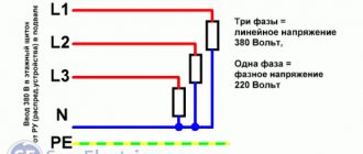
When measuring voltage, a voltmeter or multimeter must be connected to a certain section of the electrical circuit in parallel, and when measuring current, an ammeter must be placed in series. Therefore, to measure the current, an artificial break in the circuit is made and a measuring device is connected to it.
To simplify and speed up the process, clamp meters are used, which work using a completely different method. They allow you to measure the intensity of the electromagnetic field that always appears around any conductor. In this material, DC current clamps will be discussed, what is the principle of their operation and what types of current clamps are there.
Digital Clamp Meter VC3266L
Measurement with DC and AC clamps
To measure different types of current using clamps, exactly the same technique is used. The main thing is to pre-select the required operating mode.
Before using the device, you must ensure that the device is not affected by any external voltage sources.
For example, the results of the device can be distorted by some asynchronous electric motors, certain types of transformers, welding machines, and also power supplies (pulse). All of them can realize large fields with electromagnetic waves, which can induce an induced emf in the magnetic circuit.
To measure current using clamps you need:
- Moving the switch knob to the required position.
- Inserting a conductor into the magnetic circuit space.
- Reading results from the device display.
Thus, no special skills or knowledge are needed to work with ticks. Newer models have a special IFLex sensor, which is used for measurements in very cramped conditions.
If you start analyzing two conductors together, their magnetic fluxes should add up together. The display will show the overall result. For example, currents in phase and zero without leakage are equal in magnitude and opposite in value.
In such situations, the device should show a zero result. If it has any significance, we can talk about serious problems in the electricity network.
Varieties
According to types and varieties, current clamps are classified as follows.
Current clamps with dial indicator. Historically, this is the first meter to use a transformer for alternating voltage. Such a system includes a varying number of turns included in the secondary part of the circuit.
According to the principle of operation, current clamps are divided into clamps for direct and alternating current. DC clamps are not suitable for measurements on circuits and lines with alternating voltage. With “variable” clamps the opposite is true - they are equally well suited for direct and alternating current.
For example, current clamps, classified as professional, allow you to work not only with high voltages up to 1 kV, but are also equipped with the functions of a megohmmeter, which allows you to measure the insulation resistance of wires. The ohmmeter has an impressive measurement range - from 20 MOhm. The multimeter is placed in a rubberized case with shockproof inserts that protect it from damage if accidentally dropped from a height of up to 10 m, which allows you to quickly return to work from the place where the incident occurred. This is, for example, the DT-360 model.
High-power current clamps are designed for significant currents - up to hundreds and even thousands of amperes. They, for example, are capable of withstanding a powerful impulse of starting current at the moment of starting a three-phase elevator motor in the entrance, and the automatic hold function ("Hold" mode) at the moment of sudden surges in current and voltage will show the "peak" of such an impulse in amperes (and voltage, at this moment “sagging” in voltage). Some models are also equipped with a watt/varmeter function, which partially replaces the electricity consumption meter for contactless monitoring of power lines approaching the building.
If the current clamp has a multimeter, which has the ability to record readings during fluctuations in current and voltage, measured reactive power in a system log, then such a device is a contribution to the process of self-diagnosis of possible faults in a line or electrical network. Such a device, in addition to the processor, ADC, RAM and ROM chip with microprogram, contains a chip for long-term data storage - flash memory.
For the convenience of transferring data to PCs and mobile devices and processing them using special applications, the device has a microUSB interface or wireless communication via Wi-Fi or Bluetooth. But such additional comfort can cost 10 thousand rubles or more per device. For reliability, the microcircuits on the control board have protective shielding against interference. They are all securely removed, “decoupled” from the high-voltage part of the circuit, through the shunts of which high voltages of hundreds of volts pass.
All types and varieties of current clamps, both produced in Russia and imported from abroad, on the territory of the Russian Federation fall under the restrictions of GOST No. 8.366-79 “GSI. Digital ohmmeters. Methods and means of verification", MI-1202-86-GSI. This standard forms the basic requirements imposed on the production, testing and verification of all products that in one way or another combine digital ohmmeters and current clamps. For specific companies, for example, Fluke (USA), other GOSTs also apply, for example, 22261-94 and 14014-91. They apply to the verification and testing of multimeters, which also combine the functions of volt and ammeters.
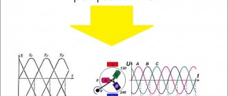
Method for measuring power with two wattmeters - with a star and delta connection
The two-wattmeter method can be used to measure power in a three-phase, three-wire wye or delta connection, balanced or unbalanced load.
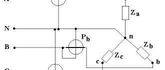
In the two wattmeter method, the current coils of the wattmeter are connected to any two lines, say R and Y, and the potential coil of each wattmeter is connected on one line, the third line, that is, B, as shown below in figure (A):
The total instantaneous power consumed by the three loads Z 1, Z 2 and Z 3 is equal to the sum of the powers measured by the two wattmeters, W 1 and W 2.
Included:
Power measurement using the two-wattmeter method with a star connection
Given the above figure (A), in which two wattmeters W 1 and W 2 are connected, the instantaneous current through the wattmeter's current coil, W 1 , is given by the equation shown below:
The instantaneous potential difference across the wattmeter coil, W 1, is defined as:
Instantaneous power measured by wattmeter, W 1 —
The instantaneous current through the current coil of the wattmeter, W 2, is determined by the equation:
The instantaneous potential difference across the wattmeter coil, W 2, is defined as:
Instantaneous power measured by wattmeter, W 2:
Thus, the total power measured by two wattmeters W 1 and W 2 will be obtained by adding equations (1) and (2).
Where, P is the total power consumed by the three loads at any given time.
Power measurement using the two-wattmeter method using a delta connection
Considering the delta connection diagram shown in the figure below:
The instantaneous current through the wattmeter coil, W 1, is determined by the equation:
The instantaneous power measured by a wattmeter, W 1, will be:
Therefore, the instantaneous power measured by the wattmeter, W 1, will be represented as:
The instantaneous current through the current coil of the wattmeter, W 2, is defined as:
Instantaneous potential difference across the wattmeter potential coil, W 2:
Therefore, the instantaneous power measured by a wattmeter, W 2, will be:
Therefore, to obtain the total power measured by two wattmeters, two equations must be performed, i.e. equation (3) and (4) need to be added.
Where P is the total power consumed by the three loads at any given time.
The power measured by a two-watt meter at any given time represents the instantaneous power consumed by three loads connected to three phases. In fact, this power is the average power consumed by the load as the wattmeter reads the average power due to the inertia of their moving system.
.