Installation of a distribution box in an apartment is an important stage of electrical wiring; thanks to it, the electric current is evenly distributed to points that consume electricity (lamps, sockets, switches). A properly installed box ensures 100% uninterrupted use of electrical wiring. In appearance, the junction box is a metal or plastic structure with holes on the sides. Wires extend from the box, which provide current to all important electrical devices.
What is a junction box for?
To distribute electricity evenly, the wiring is divided into separate groups of consumers. In rooms, distribution boxes are installed at the wiring connections.
Distribution boxes perform several important functions in residential premises:
- ensuring fire safety;
- creating an aesthetic appearance in the apartment.
The wires are located inside the box; thanks to the housing, they are not subject to mechanical stress, which ensures their safety.
According to the installation principle, the boxes are built-in and external. Built-in ones are installed in specially prepared recesses in the wall, and overhead ones are fixed on the wall surface.
For open wiring
The open arrangement of the distribution unit provides for fixing both the box itself and the boxes for laying electrical wires on top of the wall surface. This option is mainly present in electrical wiring equipment for office, industrial and commercial premises.
In private housing construction, external wiring is mainly for utility and technical rooms. The convenience of the outdoor option is quick access to the connection point of the wires, which makes them indispensable for rooms with a large number of consumers.
This division largely reflects the basic, but not the most complete classification of the characteristics of a given product. At the same time, this classification is the main one today for most sellers and consumers.
In addition to classification by type of installation, there is a classification by purpose and degree of safety of this equipment. This type of separation exists for special rooms and provides the greatest degree of safety for this type of room - protecting electrical equipment from the influence of the indoor environment.
This classification reveals more deeply the purpose of electrical distribution boxes, while each class has its own characteristics:
- Conventional protected distribution boxes - can be used both in ordinary premises and industrial premises, they are designed for a standard voltage of 220 V, most often have a lid without a rubber gasket, and the input points have standard rubber seals.
- Dust-proof boxes are designed for installation in rooms with a high content of dust or other dusty particles, the penetration of which into the housing can negatively affect the operation of the entire power supply system.
- Splash-proof options are designed for rooms with high air humidity; they have a special rubber gasket and rubber seals that provide reliable protection of the wire connection from moisture penetration inside.
- Fire resistant, increased strength. In rooms where explosive work is carried out, highly flammable liquids and materials are used, safety requirements must be ensured at the highest level; it is for such rooms that boxes are installed that ensure reliable fastening of both the wires themselves and their retention in special clamps inside the installation compartment.
Main function of distribution box
The distribution box allows you to reduce wiring costs. If it didn’t exist, each electricity consuming device would be connected with a separate cable. The absence of a box provides for an increase in the channels for laying wires, and visually this looks unaesthetic.
The advantage of using junction boxes is undeniable, and proper connection of wires will ensure the safety of the premises. This device isolates contact points from the effects of flammable wall materials.
The ease of use of the junction box ensures ease of repair. The main function of the box is that it ensures uniform distribution of electricity to the locations of the main consumers. In addition, such designs of switching boxes involve adding new branches of electrical networks to the existing wire if necessary.
Twist
The most popular method among folk craftsmen, but the most unreliable. It is not recommended by the PUE for use, as it does not provide proper contact, which can lead to overheating and a fire. This method can be used as a temporary method, for example, to check the functionality of the assembled circuit, with mandatory subsequent replacement with a more reliable one.
Correct twisting of electrical wires
Even if the connection is temporary, everything must be done according to the rules. The methods for twisting stranded and single-core conductors are similar, but have some differences.
When twisting stranded wires, the procedure is as follows:
- the insulation is stripped to 4 cm;
- the conductors unwind by 2 cm (item 1 in the photo);
- connect to the junction of untwisted conductors (pos. 2);
- the veins are twisted with your fingers (position 3);
- the twist is tightened with pliers or pliers (pos. 4 in the photo);
- insulated (insulating tape or heat-shrinkable tubing placed before the connection).
Connecting wires in a distribution box with one core using twisting is easier. The conductors, stripped of insulation, are crossed and twisted with fingers along their entire length. Then take a tool (pliers and pliers, for example). In one, the conductors are clamped near the insulation, in the second, the conductors are intensively twisted, increasing the number of turns. The connection point is isolated.
Twist with pliers or pliers
Types of distribution boxes
Distribution boxes according to the type of fastening are divided into:
- overheads, which are installed outside on the wall;
- internal, installed in the prepared wall recess.
The main purpose of the junction box is to provide easy access to the electrician in the event of a system malfunction. For convenience and to preserve the integrity of the wires, the box is closed with a lid. To carry out any manipulations with the electrical wiring, specialists just need to remove the cover and get acquainted with the causes of the problems.
Distribution boxes are made from the following materials:
- Plastic.
- Metal.
Metal cases are made of tinned steel sheets or aluminum alloys. The main requirement for materials is that they are not subject to corrosive changes.
If a distribution box is needed for strategically important facilities, then it must be selected with the following characteristics:
- screw cap;
- waterproofing gaskets.
The metal case has universal properties and perfectly protects the wiring during a fire, that is, during a fire, the metal structure is able to preserve the contents of the box for some time, during which it is possible to de-energize the network.
The plastic case also has positive properties: resistance to oxidative processes and the ability to isolate electric current.
Distribution boxes vary in geometric shape and are:
- round;
- square;
- rectangular.
If a small number of wires are supplied to the box, then a round box configuration can be used. In cases of a large number of wires, it is better to use a rectangular distribution structure.
Important! If the walls are concrete, then it is easier and more convenient to install round box structures.
The dimensions of distribution boxes depend on the number of wires and their cross-section.
Pue section 2 (2003)
Chapters 2.4, 2.5 are as revised in the seventh edition (2003)
SCOPE, DEFINITIONS
2.1.1.
This chapter of the Rules applies to electrical wiring of power, lighting and secondary circuits with voltage up to 1 kV alternating and direct current, carried out inside buildings and structures, on their external walls, on the territories of enterprises, institutions, microdistricts, courtyards, personal plots, on construction sites using insulated installation wires of all cross-sections, as well as unarmored power cables with rubber or plastic insulation in a metal, rubber or plastic sheath with a cross-section of phase conductors up to 16 mm2 (for a cross-section of more than 16 mm2 - see Chapter 2.3).
Lines carried out by uninsulated wires indoors must meet the requirements given in Chapter. 2.2, outside buildings - in chap. 2.4.
Branches from overhead lines to inputs (see 2.1.6 and 2.4.
2), performed using insulated or non-insulated wires, must be constructed in compliance with the requirements of Chapter. 2.
4, and branches made using wires (cables) on a supporting cable - in accordance with the requirements of this chapter.
Cable lines laid directly in the ground must meet the requirements given in Chapter. 2.3.
Additional requirements for electrical wiring are given in Chapter. 1.5, 3.4, 5.4, 5.5 and in Sect. 7.
2.1.2. Electrical wiring is a set of wires and cables with their associated fasteners, supporting protective structures and parts installed in accordance with these Rules.
2.1.3. Cable, cord, protected wire, unprotected wire, cable and special wire - definitions according to GOST.
2.1.4. Electrical wiring is divided into the following types:
1. Open electrical wiring - laid along the surface of walls, ceilings, along trusses and other construction elements of buildings and structures, along supports, etc.
When open electrical wiring is used, the following methods of laying wires and cables are used: directly on the surface of walls, ceilings, etc.
, on strings, cables, rollers, insulators, in pipes, boxes, flexible metal sleeves, on trays, in electrical skirting boards and platbands, free suspension, etc.
Open electrical wiring can be stationary, mobile and portable.
2. Hidden electrical wiring - laid inside the structural elements of buildings and structures (in walls, floors, foundations, ceilings), as well as along ceilings in floor preparation, directly under a removable floor, etc.
For hidden electrical wiring, the following methods of laying wires and cables are used: in pipes, flexible metal hoses, ducts, closed channels and voids of building structures, in plastered grooves, under plaster, as well as by embedding them into building structures during their manufacture.
2.1.5. External electrical wiring is electrical wiring laid along the outer walls of buildings and structures, under canopies, etc., as well as between buildings on supports (no more than four spans up to 25 m long each) outside streets, roads, etc.
External electrical wiring can be open or hidden.
2.1.6. The input from an overhead power line is the electrical wiring that connects the branch from the overhead line with the internal electrical wiring, counting from insulators installed on the outer surface (wall, roof) of a building or structure to the terminals of the input device.
2.1.7. A string, as a load-bearing element of electrical wiring, is a steel wire stretched close to the surface of a wall, ceiling, etc., intended for attaching wires, cables or their bundles to it.
2.1.8. A strip, as a load-bearing element of electrical wiring, is a metal strip fixed close to the surface of a wall, ceiling, etc., intended for attaching wires, cables or their bundles to it.
2.1.9. A cable as a load-bearing element of electrical wiring is a steel wire or steel rope, stretched in the air, intended for hanging wires, cables or their bundles from them.
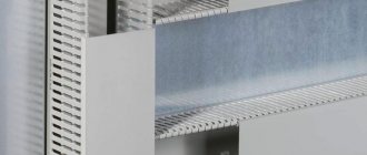
2.1.10. A box is a closed hollow structure of rectangular or other cross-section, intended for laying wires and cables in it. The box should serve as protection against mechanical damage to the wires and cables laid in it.
Boxes can be blind or with openable lids, with solid or perforated walls and lids. Blind boxes should have only solid walls on all sides and no lids.
The boxes can be used indoors and outdoors.
2.1.11. A tray is an open structure designed for laying wires and cables on it.
The tray does not protect against external mechanical damage to the wires and cables laid on it. Trays must be made of fireproof materials. They can be solid, perforated or lattice. The trays can be used in indoor and outdoor installations.
Source: https://www.proftrade.ru/normative/d-19/c-10/doc-1074.html
Internal structure of distribution box
The design of the junction box consists of a housing and a cover, as well as side inlet holes.
The internal cavity of the box is equipped with terminals and clamps for fastening wires. Typically, the input cable is secured using terminals, and separate wires are secured using clamps. If the box is not equipped with terminals, the wires are secured together by twisting.
The disadvantage of a terminal connection is that after use the bolts can become loose and disrupt the wiring contact. Loose contact causes heating and subsequently burning of the wires. Twisting is considered a more reliable method.
It should be taken into account that the connection of aluminum and copper wires in the junction box leads to destruction of the connection and the occurrence of an electrochemical process.
Important! Brass terminals provide high-quality connection of aluminum and copper wires.
Soldering
If you have a soldering iron in the house and you know how to handle it at least a little, it is better to use soldering. Before twisting, the wires are tinned: a layer of rosin or soldering flux is applied. The heated soldering iron is dipped in rosin and passed several times over the part that has been stripped of insulation. A characteristic reddish coating appears on it.
Soldered wires
After this, the wires are twisted as described above (twisting), then they take the tin on a soldering iron, heat the twist until the molten tin begins to flow between the turns, enveloping the connection and ensuring good contact.
Installers do not like this method: it takes a lot of time, but if you are connecting the wires in the junction box for yourself, spare no time and effort, but you will sleep peacefully.
Installation
During electrical installation work in houses of concrete or brick construction, electrical devices are placed in the wall cavity in specially prepared holes in the wall. Such recesses are made with a hammer drill; in cases of a round design of the distribution panel, the holes are made with a special crown. In the seat, the box is attached to the wall using alabaster mortar, which guarantees a strong connection between the housing and the wall.
After determining the installation location of the box, you need to prepare the wire network and make the connection. In order to bring them to the switching box, you need to prepare grooves into which the wires will be laid. If the walls allow the possibility of wiring in a horizontal position, then the gaps between the walls and the ceiling are quite useful for this.
After preparing the channels and socket boxes, the wiring of the switching box wiring system is carried out.
Important! To ensure the correct connection of the wires in the junction box for the purpose of quickly carrying out subsequent repair work, the wires are marked.
The input cable from the electrical panel is designated as “input”; the wire from the sockets should also be marked, because labeled wires will not allow mistakes during maintenance and repair. In order for the wires to be used correctly, the cross-section must be strictly observed; for example, to supply electricity from the panel, a two or three-core cable with a cross-section of 4 square millimeters is used.
Such a cable guarantees full use of any high-power consumer. For the lighting system, a cross-section of 2.5 square millimeters is used, and for sockets - 1.5 square mm.
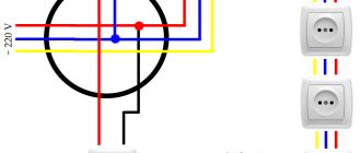
After familiarizing yourself with all the nuances, they begin to install the junction box. The basic principle of installing the switching structure is indicated by precise adherence to the sequence of wiring connections. The wiring diagram in the distribution box includes the following parameters: phase is connected to phase, zero is connected to zero, and grounding is connected to grounding.
Laying of wires occurs subject to compliance with all parameters and requirements of the drawn up connection diagram. The wires are laid inside the box, preferably with an allowance of about 10 centimeters. When connecting wires, it is necessary to strip the ends of insulation and secure them in the terminals.
If there are no fasteners, you can simply fix the connections by twisting. This method involves twisting the wires at the points of contact; this method is often used and is considered reliable. After this, the joints are fixed with insulating material (insulating tape or plastic caps).
Important! The wires are mounted in pipes made of metal or plastic, which provide insulation from external negative factors.
Various modifications of switching devices are widely presented in specialized electrical stores. The included instructions indicate the main characteristics and current voltage ratings.
Design Features
Installing electrical wiring without junction boxes is a technique that has appeared relatively recently. Despite this, in some cases this installation scheme does not contradict the basic documents of PTEEP and PUE. At the same time, the method itself still causes controversy in professional circles.
In this case, the wiring diagram has some differences from the one used when installing junction boxes. Without distribution boxes, the electrical wiring is also powered from a switchboard with an automatic circuit breaker. From it the wire is directed to the first socket and then stretches in a loop to the others.
The three-core cable (neutral, phase and ground) suitable for the first outlet is cut. Zero and phase are broken. But the grounding cannot be interrupted; it must reach the contacts of the third socket. Therefore, the two stripped wires must be connected to the corresponding incoming contacts. Then the zero and phase are sent in a loop to the next socket, connecting and tightening well with a screwdriver at the input contact.
In this case, the grounding cable is stripped. The cleaned wire is bent in half. Thus, we get two wires in contact with each other, which have a common core.
After this, a piece of wire is stripped on both sides. One end must be attached to the bent ground. As a result, we get three bare areas, which we press with a special sleeve and insulate. We bring the second end to the contact of the socket intended for grounding and clamp it. Thus, we avoid gaps and fulfill everything according to the documentation requirements.
After this, we connect the wire through the groove to subsequent sockets. In this case, a phase interruption and zero occurs. Terminal blocks are used to secure them.
It is worth noting that such installation of electrical wiring can cause some difficulties when using cheap sockets. Such products often have weak contacts. Because of this, the wires in them can become very hot, causing the wiring to burn out or cause a fire. Also, the ends of the cables may fall out of the contacts, leading to disruption of the power supply circuit in other outlets.
To avoid a similar situation with such a wiring installation scheme, the grounding wire (both zero and phase) is cut through. In addition, you can crimp cables, making taps not only for grounding, but also for phase and neutral. In this case, the sleeves used for crimping must be insulated. They are placed in the socket box, and the taps are then connected to similar contacts.
In the described wiring diagram, the socket box will serve as a distribution box. Therefore, the use of junction boxes will not be carried out here.
In order for such installation to take place quickly and without problems, experts recommend buying socket boxes that are longer. This way they will fit all the necessary wires.
Connection principles
For quick connection and to avoid confusion, the wires are marked with colors of different shades. The following color combination is considered popular: white indicates phase, blue indicates zero, and light green symbolizes grounding. When connecting, strict compliance and consistency must be observed.
Like any other work, electrical wiring in a junction box also begins with a design. To draw up a competent electrical wiring diagram, you need to determine the exact location of electrical installation points - lamps, sockets, switches. In accordance with the diagram, distribution boxes are placed in convenient places. Providing access is necessary for carrying out repair and maintenance work in case of interruptions in the electricity supply.
The rules for electrical installations stipulate that wires must be connected by soldering, welding or using clamps. However, the “old-fashioned” method of twisting wires has proven itself among the people; this method ensures the manufacturability and reliability of the system.
Sometimes twisting the wires is not enough; to ensure reliability, the contact area is treated with soldering. After connecting, the wires are insulated and placed in the box body so that they do not come into contact with each other.
After carrying out the entire complex of work, diagnostics are carried out; for this, the most powerful electrical appliance in the apartment is connected to the network and the wires are checked for the presence of heating. If you find any wire heating up, this means that it does not have enough contact area, and in such cases the junction box should be repaired, possibly replacing the wire with a larger cross-section wire.
Purpose, pros and cons
Like any device, the distribution box performs primary and secondary functions depending on the characteristics of the electrical circuit:
- Protection of the cable and its cores from dust , foreign interference and mechanical defects.
- Fire protection , increased fire resistance.
- Modern boxes are capable of connecting wires from different metals.
A significant advantage of the distributor is the cost-effectiveness of cable consumption . There is no need to run a separate wire to each point of consumption; it is possible to connect a single power line.
The main disadvantage is a decrease in the reliability and safety of using electrical wiring for domestic and industrial purposes due to the illiterate use of twists. In this case, the insulating qualities of the wiring are destroyed.
Security measures
The most important thing when installing a distribution box is compliance with basic safety measures. Wires of different metals should be connected only through adapters, and not directly. Plus, do not confuse phase with neutral and ground. And before closing the junction box with decor, if a hidden wiring option is chosen, you should check the entire system for functionality.
Standard color scheme for phase identification
Terminal blocks
Another connection of wires in the distribution box is using terminal blocks - terminal blocks, as they are also called. There are different types of pads: with clamps and screw ones, but, in general, the principle of their design is the same. There is a copper sleeve/plate and a wire fastening system. They are designed in such a way that by inserting two/three/four conductors into the right place, you connect them securely. The installation is very simple.
Screw terminal blocks have a plastic housing in which the contact plate is fixed. They are of two types: with hidden contacts (new) and with open contacts (old style). In any of them, a conductor stripped of insulation (length up to 1 cm) is inserted into the socket and clamped with a screw and a screwdriver.
Connecting wires in a junction box using terminal blocks
Their disadvantage is that it is not very convenient to connect a large number of wires in them. The contacts are arranged in pairs, and if you need to connect three or more wires, you have to squeeze two wires into one socket, which is difficult. But they can be used in branches with significant current consumption.
Another type of block is Vago terminal blocks. These are pads for quick installation. There are mainly two types used:
- With flat spring mechanism. They are also called disposable, since their reuse, if possible, is with a significant deterioration in the quality of contact. The point is in the internal structure: in the body there is a plate with spring petals. When inserting a conductor (single-core only), the petal bends, clamping the wire. Providing contact, it cuts into the metal. If the conductor, with due effort, can be pulled out, then the petal will no longer take its previous shape. That is why this type is considered disposable. Despite this, the connection is reliable and they can be used. There are also special terminal blocks of the same shape, but in a black housing. They contain electrical paste inside. These connectors are necessary if you have to connect copper and aluminum, which simply do not fit together due to the active electrochemical processes that occur between them. The paste prevents oxidation, allowing the two metals to be joined easily.
Vago terminal blocks
- Universal with lever mechanism. This is perhaps the most convenient connector. Insert the bare conductor (the length is written on the back side), press the small lever. The connection is ready. If you need to reconnect the contact, lift the lever and remove the wire. Comfortable.
The peculiarity of these terminal blocks is that they can only be used at low currents: up to 24 A with a copper wire cross-section of 1.5 mm, and up to 32 A with a cross-section of 2.5 mm. When connecting loads with high current consumption, the wires in the junction box must be connected in a different way.
Welding wires
If you have an inverter welding machine, you can use a welding connection. This is done on top of the twist. Set the welding current on the machine:
- for a cross section of 1.5 mm2 about 30 A,
- for a cross section of 2.5 mm2 - 50 A.
The electrode used is graphite (this is for welding copper). Using grounding pliers, we carefully cling to the upper part of the twist, bring the electrode to it from below, briefly touch it, achieving ignition of the arc, and remove it. Welding occurs in a fraction of a second. After cooling, the joint is insulated. Watch the video for the process of welding wires in a junction box.
Dimensions
This parameter depends on the installation location, number of outputs and version:
Table 1
| Image | Names | Dimensions | Number of pins | ||
| A | IN | N | |||
| For external wiring with glands | |||||
| 3001 | Diam. 70 | 36 | 4 | ||
| 3002 | 80 | 80 | 36 | 7 | |
| 3011 | 100 | 100 | 55 | 7 | |
| 3012 | 153 | 110 | 63 | 8 | |
| 3013 | 160 | 135 | 83 | 10 | |
| 3014 | 220 | 170 | 85 | 10 | |
| 3015 | 310 | 240 | 124 | 12 | |
| For external wiring without glands | |||||
| BJB1-100 | 100 | 100 | 55 | 6 | |
| BJB1-120 | 120 | 80 | 50 | 6 | |
| BJB1-150 | 150 | 110 | 70 | 10 | |
| BJB1-190 | 190 | 140 | 70 | 10 | |
| BJB1-100 | 150 | 110 | 110 | 6 | |
| JLB-90 | 90 | 42 | 40 | 10 | |
| For drywall, with cover | |||||
| 3251 | 100 | 100 | 45 | ||
| 3252 | 160 | 100 | 50 | ||
| 3253 | 200 | 130 | 60 | ||
| 3254 | Diam.67 | 39 | |||
| Economy box for external wiring | |||||
| JBR-065 | Diam.65 | 35 | 4 x 20 mm | ||
| JBR-070 | Diam.70 | 40 | 4 x 20 mm | ||
| JBR-080 | Diam.80 | 40 | 4 x 20 mm | ||
| JBS-065 | 65 | 65 | 40 | 7 x 20 mm | |
| JBS-070 | 70 | 70 | 40 | 6 x 20 mm | |
| JBS-080 | 85 | 85 | 40 | 6 x 20 mm | |
| JBS-100 | 100 | 100 | 55 | 6 x 25mm | |
| JBS-120 | 120 | 80 | 50 | 6 x 25 mm | |
| JBS-150 | 150 | 110 | 70 | 10 x 25 mm | |
| JBS-190 | 190 | 140 | 70 | 10 x 32 mm | |
| JBS-210 | 210 | 150 | 100 | 6 x 50 mm2 x 32 mm | |
| JBS-300 | 300 | 250 | 120 | 12 x 32 mm | |
Here are the dimensions of some types of distribution devices to give a general idea of the subject.