Main points of requirements and rules
Recently, due to cost savings, many people are starting to install electrical wiring themselves. An ordinary person does not need to know all the points of SNiP and PUE, but the basic norms and requirements will help to carry out the installation correctly and safely.
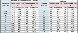
Selection of wire cross-section
According to statistics, most fires occur due to poor electrical wiring. But there is another factor such as overload. Before we figure this out, let's look at one more concept - electrical installation. If you turn to the dictionary or the same rules, you can find out that this concept hides the designation of a group of electrical equipment operating in one place and interconnected. All this equipment creates a certain load on the electrical wiring. If the load exceeds the current that the wire cross-section can withstand, the same overload is created. It heats up, and then the wiring lights up.
The electrical installation of the apartment consists of all household appliances powered by electricity. This necessarily includes the input node, represented by the distribution board. Inside the panel there must be automatic circuit breakers installed to protect the electrical wiring. They turn off the voltage supply if the current exceeds the rated value for a long time. But when the cross-section of the wire itself is less than the norm, it will not withstand the rated current strength at which the machine will have time to operate. The result is a fire in the wiring.
There are requirements that state that electrical wiring inside modern apartments must be made of copper cable covered with non-flammable insulation. Aluminum wires are a thing of the past, as they cannot withstand the full load of modern household electrical appliances.
According to the standards, the following types of cable are used:
- to connect the apartment input to the distribution board, use VVG-2 with a cross-section of 6 mm2 or VVG-5 with a cross-section of 6 mm2;
- for installation of main wiring lines and connections to sockets, VVG-3 with a cross-section of 2.5 mm2 is used;
- All branches to switches and lighting devices are laid with VVG-3 wire with a cross-section of 1.5 mm2.
All these requirements are specified in the rules of SNiP and PUE. The principle of calculations is based on the fact that the cross-section of the electrical wiring must withstand the rated load limited by the circuit breaker.
Requirements for the number of wire cores
Returning to the same PUE rules, in the 7th edition you can find requirements stating that all electrical wiring of a residential premises must be done with a three-core copper cable. The third core is needed for grounding.
There are two types of grounding systems, differing in the zero separation point:
- TN-S system with working zero separation (N);
- TN-CS system with protective zero separation (PE).
Be that as it may, a cable with three conductors must exit from the electrical panel into the room, that is, phase (L), zero (N) and, of course, ground (PE).
The grounding wire protects a person from electric shock, as well as all household electrical appliances from burnout. When installing electrical wiring, special attention must be paid to the grounding conductor. If it breaks at a bad terminal connection, during a phase breakdown on the body of any electrical appliance, dangerous voltage will flow to all household appliances connected to the sockets.
To avoid an unexpected breakage, you cannot connect the wires with twists. For these purposes, there are special terminal blocks that differ in different wire clamping mechanisms. As a last resort, you can perform soldering. All connections must be located in junction boxes, socket boxes and panels so that they can be easily accessed.
When there is old aluminum wiring in the room, it is better to replace it with new copper wiring. If this is not possible, connecting copper conductors to aluminum conductors is allowed only with special terminal blocks.
Requirements for the placement of sockets, switches and electrical wiring
You cannot place sockets and switches randomly around the room. There are SNiP 23-05-95 requirements here, which read:
- Switches are mounted at a maximum distance of 100 mm from the doorway on the side where the door handle is located. There are no special requirements for the installation height in the apartment, the main thing is that it is convenient to use. There are requirements for children's institutions, where the distance of the switch from the floor should be 1.8 m.
- According to SNiP standards, one socket can be installed per 6 m2 of room. But according to the same rules, it is prohibited to connect permanently installed powerful household appliances through carriers. In such cases, it is allowed to install as many sockets as is necessary to connect household electrical appliances. Often such situations occur in the kitchen, where one outlet is not enough.
- Bathroom sockets must have an appropriate moisture protection class. They are placed no closer than 600 mm from objects that generate splashes and are connected through an RCD. Sockets are allowed to be placed where they are convenient to use. The only requirement is a minimum distance of 100mm from the floor, windows and doors, and 200mm from the ceiling.
As for the wiring, more precisely, the branches to sockets and switches, the cable should be removed from the gas pipeline by 500 mm, and from other communications by 40 mm.
Existing types of wiring
SNiP requirements state that all wiring cables must be laid in strictly horizontal or vertical lines. There are several types of correct electrical wiring installation:
- Hidden wiring is considered the safest and most aesthetically pleasing. It is laid under the floor, in the voids of floor slabs, on walls under plaster. If the structural element of the house is made of flammable material, then the cable is protected with a metal sleeve;
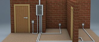
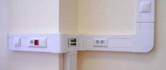
- External wiring is considered the simplest. It is laid in special channels attached to the wall. The advantage of such a system is the ease of access to the cable for repairs, but such wiring does not look aesthetically pleasing in a residential area.
There is a third type of electrical wiring - combined. It includes a combination of the two previous types. For example, the main line is hidden under the floor or on the ceiling, and the descents to sockets and switches are made open. The combined method is used extremely rarely, and then mainly for utility rooms.
Most often, a hidden installation method is used, but here it is advisable to provide for the possibility of replacing the cable if it fails.
It is optimal to lay the wires in a corrugated sleeve so that they can be removed and replaced without destroying the plaster. The corrugation is laid in the same grooves cut with a grinder or wall chaser. By the way, SNiP rules prohibit cutting metal reinforcement when cutting grooves on reinforced concrete structures. It is also unacceptable to use joints of panel blocks instead of grooves.
Automatic circuit breakers
All electrical lines in the house must be protected by automatic devices. They are installed in the switchboard according to the following principle:
- all lighting lines are connected to circuit breakers rated at 16 A;
- a 20 A circuit breaker is installed on the line of sockets;
- sockets for connecting powerful household electrical appliances are led out in a separate line to the distribution board with connection through a 25 A circuit breaker.
In addition to circuit breakers, all electrical wiring is equipped with an RCD that is triggered by a current leak of 100 mA. Each line is additionally separately connected to an RCD, designed for a leakage rate of 10–30 mA.
Line layout diagrams
All current consumed in the apartment by various electrical appliances is summed up in the distribution board, where it is taken into account by the electric meter. The main load falls on the input cable, so it is mounted with a large cross-section. Wires of a smaller cross-section are supplied to each consumer, since the load on them is less.
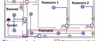
Based on these requirements, there are 3 wiring schemes:
- A loop circuit is also called a bus connection. It involves laying a traditional common line of thick cable, from which branches with thin wires go to the consumer through distribution boxes.
- A radical connection is considered more reliable and convenient. It is based on supplying separate lines from the panel to each consumer. The downside is the high costs due to the use of a large amount of cable.
- The third scheme is called combined. It consists of the first two.
Recently, in many apartments, electricians are installing a combined circuit.
GOST R 50571.5.52 requirements for external electrical wiring
Standard GOST R 50571.5.52-2011.
“Low-voltage electrical installations. Part 5-52. Selection and installation of electrical equipment. Electrical wiring”, with a few exceptions, establishes requirements for electrical wiring without dividing them into internal and external. We can highlight the most important requirements, which also apply to external electrical installations.
In accordance with 521.6 GOST R 50571.5.52:
— electrical wiring systems in pipes must comply with IEC 61386 (GOST R IEC 61386.1-2014 Pipe systems for laying cables. Part 1. General requirements is in force in Russia);
- electrical wiring systems in cable or special cable boxes - IEC 61084 (GOST R IEC 61084-1-2007 Cable and special cable boxes systems for electrical installations. Part 1. General requirements);
- electrical wiring systems on cable trays and cable ladders - IEC 61537 (GOST R 52868-2007 Cable tray systems and cable ladder systems for laying cables. General technical requirements and test methods).
Chapter 522 GOST R 50571.5.52 “Installation of electrical wiring under external influences” contains important requirements regarding the protection of electrical wiring from moisture, tensile forces on vertical sections of the route from its own weight, displacement of building structures and other mechanical influences.
Chapter 527.1 GOST R 50571.5.52 “Safety measures within a separate fire-restricted room” contains instructions on what standards materials classified as non-combustible must meet so that they can be used without special precautions.
It should be borne in mind that if part of the electrical wiring is located inside the building (for example, in the case of connecting an architectural facade lighting panel to the building's ASU), then all cables laid in the building before they exit to the facade must meet the requirements of Chapter 527.1, as well as the requirements other regulatory documents related to electrical installations of buildings. In this case, all cables laid in the building up to the first branch box located on the facade must meet the requirements of GOST 31565-2012 “Cable products. Fire safety requirements."
Chapter 527.2 GOST R 50571.5.52 “Sealing passages of electrical wiring” contains requirements that must be met in the case of cables being taken out of the room to the facade of the building, as well as for sealing electrical wiring laid in pipes and ducts.
Chapter 528 GOST R 50571.5.52 “Proximity of electrical wiring with other utility networks” establishes requirements for electrical wiring in close proximity to various utility lines.
Part of the requirements of Appendix F directly applies to external electrical wiring. Here are the characteristics for pipes according to the classification according to IEC 61386 (GOST R IEC 61386.1-2014 is in force in Russia). For external electrical wiring, it is recommended to use pipes that have the parameters “Degree of compression resistance” and “Degree of impact resistance” not lower than class 3 (medium) according to GOST R IEC 61386.1. In accordance with the requirements of 6.1 GOST R IEC 61386.1, pipes according to the above parameters are divided into: class 1 - very light, class 2 - light, class 3 - medium, class 4 - heavy, class 5 - very heavy).
At the same time, in Appendix F of the GOST R 50571.5.52 standard there is no division of pipes into metallic and non-metallic, but only the mechanical properties of the pipe are indicated.
Installation of hidden electrical wiring
Hidden electrical wiring can be laid in walls, on the ceiling and under the floor. Here you need to be prepared for severe contamination of the apartment due to the cutting of grooves and the dismantling of part of the floor covering.
Laying cables in walls
The most common method is to lay the cable in grooves cut into the walls. Work begins with marking the entire room. An exact copy of the completed wiring diagram is transferred to the walls and ceiling. It is convenient to cut the grooves with a wall chaser, but if you don’t have one, a grinder or hammer drill will do. There are no special requirements for the size of the grooves. It is necessary to ensure that the cable or corrugated sleeve fits freely inside, provided that they are covered with a 10 mm layer of plaster on top.
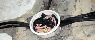
Inside the grooves, the cable is fastened every 500 mm. Many people do this with a simple gypsum solution, applying it at a certain distance. It will be more reliable to secure the wiring using dowels and clamps. Socket boxes are installed at connection points for sockets and switches, and distribution boxes are attached to connect branches. The free ends of the wire are led into socket boxes and distribution boxes, where the final connections of all contacts with terminal blocks into the general circuit take place.
The last thing to do is to connect the input cable inside the electrical panel. After this, voltage is applied to the network and, if everything works properly, you can begin sealing the grooves with plaster. Naturally, filling the grooves and all other similar work is carried out with the electricity turned off.
Cable laying under the floor
A more economical option is to lay the main line under the floors. This is easier to do when there is no floor covering yet. Otherwise, some part of it will have to be dismantled. The essence of the method is to lay hoses made of corrugated or ordinary pipes under the floor for each cable separately. The wire must penetrate freely inside the sleeve so that it can be replaced in the future without dismantling the floor covering.
The distribution panel is mounted on the wall. An input cable is connected to it from under the floor. Further connections to the machines will take place inside the panel. At the points where branches exit to sockets, switches and lighting devices, cable outlets 200 mm long are left from under the floors. Distribution boxes are installed here. All further connections occur in the same way as when laying the cable in the walls.
Ceiling cable routing
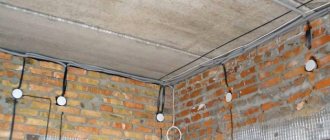
Things are simpler in panel houses. Many electricians lay cables inside the voids of interfloor slabs. Most often, room lighting lines are placed here. To avoid cutting grooves, a branch from the wall is pulled through the void of the slab and the wire is released from a drilled hole in the center of the ceiling to connect the lighting fixture.
Inside the ceiling, you can organize a common line, then only branches for sockets and switches will go to the walls. At the places where the cable turns and where the wires are connected in the junction box, an outlet of a maximum of 150 mm from the ceiling is made at a right angle.
Installation of electrical wiring according to the electrical installation rules (PUE)
Unlike the mass of existing standards in various fields, the PUE is not a new product, but an old-timer - the first edition of the rules dates back to 1946. With the development of technology and stricter requirements for the safety and reliability of electrical systems, these rules have undergone changes over and over again. Today, the “electrician’s handbook” is already in its 7th edition, valid since November 2003 (last changes 2016). But, by and large, this is a modernized version of the 6th edition, introduced into use by the USSR Ministry of Energy in 1985, from which some sections and chapters were removed, and some were added. In particular, we have tightened the requirements for the safety of electrical networks in order to maximally comply with international standards in this area.
According to the PUE, the choice of types of electrical wiring and installation methods is based on fire safety conditions. In table 2.1.3. All possible options are listed.
| Type of electrical wiring and method of laying on foundations and structures | Made from fireproof and flame retardant materials | Wires and cables |
| Made from combustible materials | ||
| Open wiring | ||
| On rollers, insulators or with a layer of fireproof materials | Directly | Unprotected wires, protected wires and cables sheathed in combustible materials |
| Directly | Directly | Protected wires and cables sheathed from fireproof and fire-resistant materials |
| In pipes and boxes made of fireproof materials | In pipes and boxes made of fire-resistant and non-combustible materials | Unprotected and protected wires and cables sheathed from combustible, non-combustible materials |
| Hidden electrical wiring | ||
| With a lining of fireproof materials¹ and subsequent plastering or protection on all sides with a continuous layer of other fireproof materials | Directly | Unprotected wires; protected wires and cables sheathed in combustible materials |
| Lined with fireproof materials¹ | Directly | Protected wires and cables sheathed in flame retardant materials |
| Directly | Directly | The same, from fireproof |
| In pipes and ducts made of non-combustible materials - with lining under the pipes and ducts of non-combustible materials¹ and subsequent plastering² | In pipes and ducts: from combustible materials - enclosed, in grooves, etc., in a continuous layer of non-combustible materials³ | Unprotected wires and cables sheathed in combustible, non-combustible and non-combustible materials |
| The same from fireproof materials - directly | The same from flame retardant and non-combustible materials - directly | Unprotected wires and cables sheathed in combustible, non-combustible and non-combustible materials |
Notes:
¹ A lining made of fireproof materials must protrude from each side of the wire, cable, pipe or duct by at least 10 mm.
² Plastering of the pipe is carried out with a continuous layer of plaster, alabaster, etc., at least 10 mm thick above the pipe.
³ A continuous layer of fireproof material around the pipe (box) can be a layer of plaster, alabaster, cement mortar or concrete with a thickness of at least 10 mm.
Despite the fact that PUEs have been in effect for more than half a century, not everyone understands that they also apply to residential buildings. Thus, to one of the previous articles devoted to methods of installing electrical wiring in houses made of various materials, the following comment appeared:
DmitryIgonin FORUMHOUSE Member
By the way, PUEs have nothing to do with the issue under consideration, since they are intended for industrial facilities. Look at the preamble!
kungurov FORUMHOUSE Member
Excerpt from the PUE:
“The book contains requirements for the installation of electrical lighting in buildings, premises and structures for various purposes, open spaces and streets, as well as requirements for the installation of advertising lighting. Contains requirements for electrical equipment of residential and public buildings, entertainment enterprises, club institutions, sports facilities...”
Installation of open electrical wiring
The essence of open installation is to lay the cable in special boxes. This is done only on the walls and ceiling. Work begins with the same layout of the room. Boxes are attached to the drawn lines using dowels and self-tapping screws at 500 mm intervals. External distribution boxes are installed opposite the branches. Sockets and switches are also used only externally. Connecting all the wiring occurs in exactly the same way as for hidden wiring, only here you do not need to cover the grooves with plaster. The boxes with the cable inside are closed with decorative covers.
Methods for installing sockets and switches
Depending on the type of wiring, external or built-in sockets and switches are used. External models are simply screwed to the wall with self-tapping screws or glued with glue. Under the built-in models, a recess is cut out in the wall with a crown, inside which the socket box is fixed with plaster. The socket or switch in the socket box is fixed with a clamping mechanism.
By following the rules for installing electrical wiring, almost all work can be done at home yourself. But if there are any doubts, it is better to consult with specialists.