In order for electrical equipment to function reliably, the insulation of wires and cables must meet safety requirements. This can be verified through regular checks, during which the insulation resistance is measured. This procedure must be carried out in accordance with current rules and requirements.
How is the check carried out?
Insulation resistance measurements are in most cases carried out for the purpose of checking connecting wires and cables. If they are exposed to various influences, it is especially important to be confident that the insulation resistance meets safety requirements.
The measurement is carried out based on Ohm's law. In this case, a certain voltage is applied to the insulation, and then the current flowing through it is measured. To calculate the resistance, the formula of Ohm's law is used: Riz = U/I.
Insulation resistance measurements are performed not only to monitor the safety of the electrical network, but also during regular maintenance. Measurements of the insulation resistance of electrical wiring elements are necessary in cases where the insulation remains intact. If it is missing or there are wire cuts or other damage in certain places, then there is no point in taking measurements at this moment. First you need to repair the wire or replace it with a working one.
CONDITIONS FOR PERFORMING MEASUREMENTS
- Insulation measurements must be carried out under normal climatic conditions in accordance with GOST 15150-85 and under normal power supply conditions or as specified in the manufacturer's data sheet - technical description for megohmmeters.
- The value of the electrical insulation resistance of the connecting wires of the measuring circuit must exceed at least 20 times the minimum permissible value of the electrical insulation resistance of the product under test.
- The measurement is carried out indoors at a temperature of 25±10 °C and a relative air humidity of no more than 80%, unless other conditions are provided for in the standards or technical specifications for cables, wires, cords and equipment.
Possible causes of insulation failure
Modern industry pays serious attention to the quality of insulation of wires and cables. But despite this, from time to time problems arise with it and as a result there is a need to check the resistance. Most often, control is needed if the following factors are present:
- The wire is exposed to direct sunlight. This has a destructive effect on some types of insulating materials.
- There is prolonged exposure to high voltage.
- Temperature effects are observed.
- There are mechanical damages.
- Climatic features of a particular area. This may, for example, occur in cases where it is hot or severely cold.
Timely detection of insulation problems will allow you to avoid such dangerous consequences as a short circuit or the impact of current on a person during a breakdown.
Why do you check the cable insulation resistance?
Why are these measurements taken at all? Our current flows through a conductor, which is a copper or aluminum conductor (or many conductors). And between the conductive conductor and the environment there is insulation - plastic, rubber, PVC, paper, oil.
Insulation protects the core from contact with another core, with the environment, with a person. A characteristic of insulation quality, among others, is insulation resistance. This characteristic is measured in ohms and their derivatives (kilo, mega, giga).
Resistance is the reciprocal of conductivity, that is, it shows the ability not to pass electric current. The weaker the insulation, the more likely it is that current will find a path and spread out of the cable through conductive surfaces and materials. That is, a breakdown of the cable insulation will occur on some surface.
Insulation may deteriorate for the following reasons:
- aging of insulation over time
- increased humidity
- mechanical damage
- exposure to aggressive environment
Standards
As a result of the measurements, the actual value of the wire insulation resistance is obtained. It must be compared with standard data. To understand which document needs to be used in a particular case, you need to know what standards exist. It should be taken into account that the limit values provided by them may vary significantly. There are insulation resistance standards for:
- Power or signal cables used in various environments.
- Power electrical installations intended for industrial use.
- Household appliances equipped with a power cord.
Checking the electrical insulation resistance depends on the voltage present in the electrical network. In this case, it is necessary to take into account what model of equipment is used. Before checking, you should read the relevant documents, which indicate the standards for the insulation resistance of a wire or cable. The following is a list of the most common situations for which the permissible insulation resistance is specified:
- When using electric stoves, the insulation resistance is at least 1 MOhm.
- If the cable is laid in an area where climatic conditions can be considered normal, the minimum insulation resistance is 0.5 MOhm.
- For insulation of electrical equipment consuming voltages up to 1000 V, the maximum resistance is 1 MOhm.
- If the supply voltage of the electrical device is in the range of 100–380 V, then the limitation is 0.5 MOhm.
- In cases where the supply voltage does not exceed 50 V, the insulation resistance must be at least 0.3 MOhm.
- For cables and wires used in switchboard installations, the insulation resistance standard is 1 MOhm.
MEASUREMENT PROCEDURE
4.1 Measurable indicators
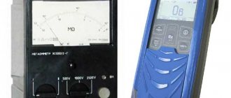
Insulation resistance is measured with megohm meters (100-2500V) with measured values in Ohm, kOhm and MOhm.
4.2 Measuring instruments
Insulation measuring instruments include megohmmeters: ESO 202, F4100, M4100/1-M4100/5, M4107/1, M4107/2, F4101. F4102/1, F4102/2, BM200/G and others, produced by domestic and foreign companies.
4.3 Qualification requirements
Trained electrical personnel who have a certificate of knowledge testing and a qualification group for electrical safety of at least 3rd, when performing measurements in installations up to 1000 V, and not lower than 4th, when measuring in installations above 1000 V, are allowed to perform insulation resistance measurements.
Persons from electrical engineering personnel with secondary or higher specialized education may be allowed to process measurement results.
Analysis of measurement results should be carried out by personnel involved in the insulation of electrical equipment, cables and wires.
What measuring instruments can be used
At first glance, it might seem that it would be logical to use a multimeter for this purpose. However, in most cases, the current that passes through the wiring is so small that this meter cannot accurately measure it. In such cases, it is convenient to use a megohmmeter, with which you can measure voltage and electric current. These devices can be analog or digital. Based on Ohm's law, the resistance value is determined from the data obtained.
The operating principle of the device can be explained using the example of an electromechanical version of a megohmmeter.
A hand generator (a) is used to supply current. In fact, we are talking about a handle that needs to be turned to generate energy. In this case, it is necessary that the rotation speed be at least two revolutions per second. An analog ammeter (b) is connected to the arrow of the device.
The instrument scale (c) is graduated to indicate the resistance value. The circuit uses several resistors (d). How many there are depends on the model of the device. There is a measurement scale switch (e). In this case, you can measure resistance in Ohms or MegaOhms. There are input terminals (f) to which wires are connected.
One of the advantages of such a device is that it does not require additional power, since the current obtained using a hand-held generator is used for measurements. However, when using it, it is necessary to take into account its inherent disadvantages:
- To ensure the required measurement accuracy, the device must remain stationary. However, this is difficult to achieve when rotating the handle.
- Accuracy is affected by how evenly the handle is rotated. It is necessary to ensure a constant voltage supply during measurement. Compliance with this condition is not always possible.
- It is difficult to measure insulation resistance with such a device alone. Therefore, two people usually work with it: one person turns the handle, the second directly checks the insulation resistance of the cable or other equipment.
The device uses a nonlinear scale, which negatively affects the accuracy of measurements. In subsequent models, manufacturers moved from turning a knob to generate current to using a power source. This helped get rid of most of the shortcomings of the electromechanical version of the device.
Most modern megohmmeters are digital. Microcircuits are actively used in their designs. The use of modern microprocessors and other microcircuits allows for relatively high measurement accuracy. When working with digital devices, it is enough to set the initial data and select the desired operating mode. Their advantages are compactness and great functionality.
1. PURPOSE OF MEASUREMENTS.
Measurements are carried out to verify compliance of insulation resistance with established standards.
2.
SAFETY MEASURES
2.1.
Organizational measures
In electrical installations with voltages up to 1000 V, measurements are carried out by order of two workers, one of whom must have an electrical safety group of at least III.
In electrical installations up to 1000 V, located in premises, except those that are especially dangerous in terms of electric shock, an employee who has group III and the right to be a work performer can carry out measurements alone.
Measurements of the insulation resistance of the rotor of a running generator are allowed to be carried out by order of two workers with electrical safety groups IV and III.
In cases where measurements with a megohmmeter are part of the content of testing work (for example, testing electrical equipment with increased power frequency voltage), it is not necessary to stipulate these measurements in the work order or order.
The provisions of this methodology are mandatory for use by specialists of the electrical laboratory in Krasnodar and the Krasnodar region of Energo Alliance LLC
2.2. Technical events
The list of necessary technical measures is determined by the person issuing the order or order in accordance with the requirements of POTEE. Insulation resistance measurements with a megohmmeter should be carried out on disconnected live parts from which the charge has been removed by first grounding them. Grounding from live parts should be removed only after connecting the megohmmeter.
3. REQUIRED VALUES
The frequency of tests and the minimum permissible value of insulation resistance must comply with those specified in the testing standards for electrical equipment and devices of the Rules for the Construction of Electrical Installations (PUE), the Rules for the Technical Operation of Consumer Electrical Installations (PTEEP). In accordance with GOST R 50571.16-99, the standardized values of insulation resistance of electrical installations of buildings are given in Table 1
Table 1.
| Rated circuit voltage, V | DC test voltage, V | Insulation resistance, MOhm |
| Systems of safe extra-low voltage (BSSN) and functional extra-low voltage FSSN) | 250 | 0,25 |
| Up to 500 inclusive, except for BSSN and FSSN systems | 500 | 0,5* |
| Above 500 | 1000 | 1,0 |
* The resistance of stationary household electric stoves must be at least 1 MOhm.
At the same time, in accordance with Ch. 1.8 PUE for electrical installations with voltages up to 1000 V, the permissible insulation resistance values are presented in Table 2.
Table 2.
| Test element | Megger voltage, V | Lowest permissible value of insulation resistance, MOhm |
| 1. DC buses on control panels and switchgears (with disconnected circuits) | 500-1000 | 10 |
| 2. Secondary circuits of each connection and power supply circuits for drives of switches and disconnectors1 | 500-1000 | 1 |
| 3. Control, protection, measurement automation circuits, as well as excitation circuits of DC machines connected to power circuits | 500 — 1000 | 1 |
| 4. Secondary circuits and elements when powered from a separate source or through an isolation transformer, designed for an operating voltage of 60 V and below2 | 500 | 0,5 |
| 5. Electrical wiring, including lighting networks3 | 1000 | 0,5 |
| 6. Switchgears4, boards and busbars (busbars) | 500 — 1000 | 0,5 |
1 Measurement is carried out with all connected devices (wire coils, contactors, starters, circuit breakers, relays, instruments, secondary windings of current and voltage transformers, etc.)
NOTE 2 Precautions must be taken to prevent damage to devices, especially microelectronic and semiconductor components.
3 Insulation resistance is measured between each wire and ground, and between every two wires.
4 The insulation resistance of each section of the switchgear is measured.
Analysis of these requirements shows contradictions in terms of testing voltage and insulation resistance for secondary circuits with voltages up to 60 V (PUE, Chapter 1.8) and BSSN and FSSN systems included in this range (50 V and below), according to GOST 50571.16-99.
In addition, the resistance of the internal circuits of input distribution devices, floor and apartment panels of residential and public buildings in a cold state in accordance with the requirements of GOST 51732-2001 and GOST 51628-2000 must be at least 10 MOhm (according to PUE, Chapter 1.8 - not less 0.5 MOhm).
In this situation, when determining the standardized values of insulation resistance before the implementation of the relevant technical regulations, one should be guided by more precise requirements.
4. DEVICES USED
To change the insulation resistance, an E6-24 megohmmeter will be used with a test voltage from 50 to 2500 V (setting step 10 V).
Limits of permissible basic absolute error in setting the test voltage, %: from 0 to plus 15.
The current in the measuring circuit during a short circuit is no more than 2 mA.
| Resistance measurement ranges | Limits of permissible basic absolute error |
| from 1 kOhm to 999 MOhm | (0.03×R+ 3 units) |
| from 1.00 to 9.99 GOhm | (0.05×R + 5 e.m.r.) (test voltages less than 250 V) |
| 10.0 to 99.9 GOhm | (0.05×R + 5 e.m.r.) (test voltages not less than 500 V) |
| from 100 to 999 GOhm | (0.15×R + 10 e.m.r.) (test voltages not less than 500 V) |
The megohmmeter provides automatic range switching and determination of units of measurement.
The error is normalized when using the measuring cable RLPA.685551.001.
5. MEASUREMENT OF ELECTRICAL EQUIPMENT INSULATION RESISTANCE
5.1. Measuring the insulation resistance of power cables and wiring
When measuring insulation resistance, the following must be taken into account:
— measurement of the insulation resistance of cables (except for armored cables) with a cross-section of up to 16 mm2 is carried out with a 1000 V megameter, and above 16 mm2 and armored ones - with a 2500 V megameter; The insulation resistance of wires of all sections is measured with a 1000 V megameter.
In this case, it is necessary to make the following measurements:
— on 2- and 3-wire lines — three measurements: LN, N-PE, L-PE;
— on 4-wire lines — 4 measurements: L1-L2L3PEN, L2-L3L1PEN, L3-L1L2PEN, PEN-L1L2L3, or 6 measurements: L1-L2, L2-L3, L1-L3, L1-PEN, L2-PEN, L3-PEN;
— on 5-wire lines — 5 measurements: L1-L2L3NPE, L2-L1L3NPE, L3-L1L2NPE, N-L1L2L3PE, PE-NL1L2L3, or 10 measurements: L1-L2, L2-L3, L1-L3, L1-N, L2-N, L3-N, L1-PE, L2-PE, L3-PE, N-PE.
If electrical wiring in operation has an insulation resistance of less than 1 MOhm, then a conclusion about their suitability is made after testing them with alternating current of industrial frequency voltage of 1 kV in accordance with the recommendations given in this publication.
5.2. Measuring the insulation resistance of power electrical equipment
The insulation resistance value of electrical machines and devices largely depends on temperature. Measurements should be made at an insulation temperature not lower than +5 С, except in cases specified in special instructions. At lower temperatures, the measurement results do not reflect the true insulation performance due to unstable moisture conditions. If there are significant differences between the measurement results at the installation site and the manufacturer's data due to the difference in temperature at which the measurements were taken, these results should be corrected according to the manufacturer's instructions.
The degree of insulation moisture is characterized by an absorption coefficient equal to the ratio of the measured insulation resistance 60 seconds after applying the megohmmeter voltage (R60) to the measured insulation resistance after 15 seconds (R15), while:
Cubs = R60/R15
When measuring the insulation resistance of power transformers, megohmmeters with an output voltage of 2500 V are used. Measurements are taken between each winding and the housing and between the windings of the transformer. In this case, R60 must be adjusted to the results of factory tests depending on the temperature difference at which the tests were carried out. The value of the absorption coefficient should differ (downwards) from the factory data by no more than 20%, and its value should not be lower than 1.3 at a temperature of 10 - 30 °C. If these conditions are not met, the transformer must be dried. The minimum permissible insulation resistance for installations in operation are given in Table 3.
The insulation resistance of circuit breakers and RCDs is produced:
1. Between each pole terminal and the opposite pole terminals connected to each other when the switch or RCD is open.
2. Between each unlike pole and the remaining poles connected to each other when the switch or RCD is closed.
3. Between all interconnected poles and the body, wrapped in metal foil. Moreover, for automatic switches for household and similar purposes (GOST R 50345-99) and
RCD when measuring according to paragraphs. 1, 2, the insulation resistance must be at least 2 MΩ, according to item 3 - at least 5 MΩ.
For other circuit breakers (GOST R 50030.2-99), in all cases the insulation resistance must be at least 0.5 MΩ.
Table 3. Minimum permissible values of insulation resistance of electrical installations with voltages up to 1000V. (Appendix 3; 3.1 PTEEP)
| Item name | Voltage | Resistance | Note | |||||||||
| megohmmeter, V | insulation, MOhm | |||||||||||
| 1 | 2 | 3 | 4 | |||||||||
| Electrical products and devices | ||||||||||||
| rated voltage, V: | ||||||||||||
| up to 50 | 100 | Must | When measuring semiconductor devices in | |||||||||
| over 50 to 100 | 250 | correspond | products must be bypassed | |||||||||
| over 100 to 380 | 500 — 1000 | instructions | ||||||||||
| over 380 | 1000 — 2500 | manufacturers, | ||||||||||
| but not less than 0.5 | ||||||||||||
| Switchgears, switchboards | 1000 — 2500 | At least 1 | When measuring semiconductor devices in | |||||||||
| and conductors | products must be bypassed | |||||||||||
| Electrical wiring, including | 1000 | Not less than 0.5 | Insulation resistance measurements in special | |||||||||
| lighting networks | hazardous areas and outdoor areas | |||||||||||
| are produced once a year. In other cases | ||||||||||||
| measurements are made once every 3 years. At | ||||||||||||
| measurements in power circuits must be taken | ||||||||||||
| measures to prevent damage to devices, especially microelectronic and semiconductor devices. | ||||||||||||
| semiconductor devices. In lighting networks, lamps must be unscrewed, sockets and switches connected. | ||||||||||||
| Secondary distribution circuits | 1000 — 2500 | At least 1 | Measurements | are produced | with | everyone | ||||||
| devices, drive power circuits | annexed | devices | (coils, | |||||||||
| switches and disconnectors, circuits | contactors, starters, switches, relays, | |||||||||||
| control, protection, automation, | devices, secondary windings of transformers | |||||||||||
| telemechanics, etc. | voltage and current) | |||||||||||
| Cranes and elevators | 1000 | Not less than 0.5 | Produced at least once a year | |||||||||
| Stationary electric stoves | 1000 | Not less than 0.5 | Produced when the plate is heated | |||||||||
| less than once a year | ||||||||||||
| DC buses and busbars | 500 — 1000 | At least 10 | Produced with disconnected circuits | |||||||||
| voltage on control panels | ||||||||||||
| Control circuits, protection, | 500 — 1000 | At least 1 | Insulation resistance of circuits, voltage up to 60 | |||||||||
| automation, telemechanics, | B, powered from a separate source, | |||||||||||
| excitation of DC machines | measured with a megohmmeter for a voltage of 500 V and | |||||||||||
| for voltage 500 - 1000 V, | must be at least 0.5 MOhm | |||||||||||
| connected to the main circuits | ||||||||||||
| Circuits containing devices with | ||||||||||||
| microelectronic elements, | ||||||||||||
| designed for voltage, V: | ||||||||||||
| up to 60 | 100 | Not less than 0.5 | ||||||||||
| above 60 | 500 | Not less than 0.5 | ||||||||||
| Power cable lines | 2500 | Not less than 0.5 | The measurement is carried out within 1 minute. | |||||||||
| Synchronous stator windings | 1000 | At least 1 | At a temperature of 10 - 30 С | |||||||||
| electric motors | ||||||||||||
| Secondary windings of measuring | 1000 | At least 1 | Measurements | are produced | together | With | ||||||
| transformers | chains attached to them | |||||||||||
An analysis of the requirements of PUE (acceptance tests) and PTEPP (operational tests) for the minimum permissible values of insulation resistance shows the presence of serious contradictions, namely: for switchgears during acceptance tests, an insulation resistance of 0.5 MOhm is sufficient, and for preventive maintenance between repairs - 1 MOhm.
This circumstance may lead to the fact that during acceptance tests the reactor plant may be considered suitable, and during the first overhaul tests it may be rejected (at 0.5 < Ris < 1 MOhm).
5.3. Measurement procedure
When measuring insulation resistance, it should be taken into account that to connect the megohmmeter to the object being tested, it is necessary to use flexible wires with insulating handles at the ends and restrictive rings in front of the contact probes. The length of the connecting wires must be minimal based on the measurement conditions, and their insulation resistance must be at least 10 MOhm. The electrical laboratory in Krasnodar and the Krasnodar region, LLC Energo Alliance, uses an E6-24 megohmmeter or its modification E6-32 to measure insulation resistance.
5.3.1 Insulation resistance measurements with an E6-24 megohmmeter are carried out in the following sequence:
1. Check that there is no voltage on the tested object;
2. Clean the insulation from dust and dirt near the connection of the megohmmeter to the object being tested;
3. Connecting cables to the E6-24 megohmmeter for measurement
insulation resistance using a cable example is shown in Figure 1.
Picture 1.
To measure resistances of more than 10 GOhm with a given accuracy, it is necessary to connect the shielded measuring cable RLPA.685551.001, as shown in the figure
Figure 2.
To eliminate the influence of surface leakage currents (for example, caused by contamination of the surface of the measured object), use connection diagrams with three measuring cables, as shown in Figures 3 and 4.
Figure 3. Connection to protective ring
Figure 4. Connection to transformer
In the first case, a protective ring is used (a piece of foil, bare wire, etc., painted black in the figure) placed on the insulator of one of the conductors, in the second, the body (or, alternatively, the core) of the transformer is shielded. When measuring insulation resistance above 10 GΩ, it is also recommended to use a shielded test cable.
When using a shielded measuring cable, it is necessary to periodically check the electrical resistance between the signal and shield plugs. The resistance must be at least 3 GOhm at a test voltage of 2500 V.
4. Turn on the device
5. Use the “Mode” button to select the required test voltage.
6. To start measurements, press the “Rx” button twice. Then take measurements within the set time. It should be taken into account that steady-state readings are reliable.
To stop the measurement early, press the “Rx” button. The results of the measurement are displayed on the screen for 20 seconds. After this, the megohmmeter switches to voltage measurement mode.
For short-term measurements, press and hold the Rx button. When the button is released, the measurement stops.
Upon completion of the measurement, the removal of residual voltage from the object automatically begins, the current value of which is displayed on the indicator: “Un” - measured voltage on the object.
7.Evaluate the measurement error.
5.3.2 Calculation of absorption and polarization coefficients.
The absorption coefficient (CABC) is used to assess the degree of humidification of the insulation of cable lines, transformers, electric motors, etc.: the rate of charging of the absorption capacitance (capacitance caused by inhomogeneities and contamination of the material, inclusions of air and moisture) of the insulation is assessed when a test voltage is applied. The absorption coefficient is automatically calculated from the insulation resistance measurement results 15 seconds (R15) and 60 seconds (R60) after the start of the measurement:
CABS=R60/ R15
The insulation condition is considered excellent if KABS>1.6 (there was a long process of charging the absorption capacity with low currents), dangerous - if KABS<1.3 (there was a short-term process of charging the absorption capacity with high currents) in the temperature range from 10 ºC to 30 ºC. In the latter case, as well as when the absorption coefficient decreases by more than 20% relative to the factory data, drying of the insulation is recommended.
To display the absorption coefficient during or at the end of the measurement, press the “Display Menu” button
Figure 5. Result of insulation resistance measurement. (Display option with absorption coefficient)
The polarization coefficient (POL) is used to assess the degree of aging of the insulation of cable lines, expensive transformers and electric motors. It takes into account changes in the structure of the dielectric and, as a consequence, an increase in the ability of charged particles and dipoles to move under the influence of an electric field. The KPOL coefficient is automatically calculated based on the results of measuring the insulation resistance 60 seconds (R60) and 600 seconds (R600) after the start of the measurement:
Kpol = R600/R60
It is recommended to use the following KPOL indicators to assess the quality of insulation:
KPOL <1 - the insulation resource has been exhausted, the process of reducing the insulation resistance begins (possibly to an unacceptable level);
1<KPOL<2 - insulation life is reduced, but further operation is possible;
2<KPOL<4 - the insulation resource is sufficient, there are no restrictions on operation; KPOL>4 - insulation life is not reduced, there are no restrictions on operation.
Note - The decision to operate an insulator with KPOL<1 should be made on the basis of additional research: more frequent checks of the insulation condition, predicting the moment the resistance decreases to an unacceptable level.
To calculate and display the polarization coefficient, you must set the “To Polarization” mode in the menu and press the “Menu” button to set the appropriate display option.
Figure 6. Insulation resistance measurement result (display option with polarization coefficient)
Note 1. - If the measurement time was not sufficient to calculate the absorption or polarization coefficients, then dashes are added in the corresponding paragraphs.
Note 2 - When making measurements on a number of objects, pay attention to the following:
— if one of the contacts of the measured resistance is grounded, then to it
It is recommended to connect the “–” socket of the megohmmeter. However, it should be taken into account that at a number of objects the permissible polarity of voltage application may
be different, and this needs to be clarified in advance. The polarity of the test voltage is indicated on the megohmmeter sockets.
— An induced DC voltage may be present on the object. In this case, it is recommended to carry out measurements twice - with a change in the polarity of the applied test voltage. This will determine the true insulation resistance value as the average of the two measurements.
Attention!
After each measurement, it is necessary to remove the capacitive charge by briefly grounding the parts of the test object to which the megohmmeter output voltage was applied.
6. REGISTRATION OF MEASUREMENT RESULTS
Based on the results of measuring the insulation resistance, specialists from the electrical laboratory of Energo Alliance LLC draw up a protocol.
Description of the measurement procedure
First you need to read the relevant regulatory document and find out what requirements apply to insulation resistance in a particular case. Next, you need to select a device with which to measure insulation resistance. For this purpose, only proven equipment should be used. Moreover, it is necessary to have an appropriate certificate. Before starting work, the object being tested must be de-energized.
Before you begin, you need to draw a diagram according to which the device you are using will be connected. To connect it, the kit usually includes two wires, each about two meters long. There are special requirements for their insulation resistance - it cannot be less than 100 MOhm. Further actions depend on which wire or cable you plan to check.
Types of testers
When operating electrical devices, digital megohmmeters of the model: F4101/4102 from 100.0 to 1000.0 V are widely used. Installers still work with tester brands M4100/1, 4100/5 and MS-05 m from 100.0 to 2500.0 V. The choice of megger size is based on rated resistance of the device under test: power cables and transformers, machines and insulators. To determine the state of insulation in electrical installations up to 1000.0 V, it is allowed to use megohmmeters from 100.0-1000.0 V, and in installations over 1000.0 V - 1000.0-2500.0 V.
Devices are also classified by the voltage generated and resistance limits in megohms:
- 500.0 V - 500.0;
- 1000.0 V - 1000.0;
- 2500.0 V - 2500.0.
Additional Information . The devices also differ in accuracy classes. The popular M4100 model has an error of no more than 1%, and the F4101 brand has an error of up to 2.5%. The selection of electrical installation testing devices is carried out taking into account acceptable performance indicators.
Electronic meter
Electronic meter
A digital or electronic tester is a modern type of equipment, equipped with a powerful generator with field-effect transistors. Measurements are made by comparing the voltage drop in a reference circuit with a fixed resistance. The results are shown on the panel. The test results saving function accumulates data for subsequent analysis. This model differs from analog devices in its compact size and light weight. Advantages of a digital tester:
- High level of accuracy, allows you to determine resistance over large sections of the circuit;
- convenient, easy-to-read digital panel;
- technological accessibility for measurement by one user;
- works great even in very busy spaces;
- convenient and safe to use.
You may be interested in this Features of luminous flux
Disadvantages of the electronic type megger:
- Requires external power source;
- high prices for products.
Electromechanical meter
Electromechanical device
These models have an analog display on the front panel of the tester and a hand crank used to rotate and generate voltage that passes through the electrical system.
Advantages of a manual megger:
- Remains important in today's high-tech world, remaining the oldest method for determining resistance values.
- No external source is required for operation.
- Low prices on the market.
Disadvantages of a manual megger:
- At least 2 people are required for operation, one to rotate the handle, the other to connect the megger to the electrical system being tested.
- Low measurement accuracy.
- Requires a large free space for placement.
- Provides an analog measurement result.
- High requirements for safety during use.
Circuit design features:
- Deflector and Control Coil - Connected in parallel with the generator, mounted at right angles to each other and maintained in polarity so as to produce torque in the opposite direction.
- Permanent magnets create a magnetic field to deflect the pointer using a North-South magnetic pole.
- Pointer - one end connected to the coil, the other deviates on a scale from infinity to “0”.
- A scale is provided at the top of the megger from the zero to infinity range and allows the user to read the value.
- Connecting a direct current (DC) source or battery.
- The test mode is generated by a generator for a manually controlled megger. A battery or electronic charger is provided for the digital megger for the same purpose.
Note! The current coil resistance helps protect the tester from any damage during testing due to the low external electrical resistance.
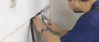
Checking the electrical wiring
First, the wire is inspected for obvious damage. If they are, then the wire must be repaired or replaced. If the shell is intact, then check the connection of this wire to the socket or switch.
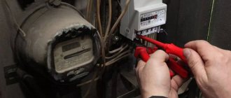
A megohmmeter is connected to the phase and neutral conductors, then the resistance should be measured. Similar actions are repeated for the phase wire and grounding.
In the case when the value of the measured resistance corresponds to the established standard, the test ends. If not, then the wires are divided into smaller sections and the procedure is repeated. In this way, they find a place where the device indicator is much lower compared to what the resistance should be according to the standard.
What devices are used?
Before starting work, you need to measure the ambient air temperature.
Why is this necessary? If a cable line contains water particles during freezing temperatures, they will turn into ice under the influence of frost, and ice is a dielectric that has no conductivity. Therefore, when the resistance is measured at a negative temperature, these pieces of ice will not be detected. Then, in order to measure the insulating layer of the wiring (its resistance), it is necessary to have special instruments and diagnostic tools. You can measure resistance with a special device called a megohmmeter (pictured below).
Using a megohmmeter you can measure resistance at a voltage of 2500 V (insulation of low-voltage and high-voltage lines). The measurement takes place at a voltage of 500–2500 V of control power lines (control circuits, power circuits, short circuits, etc.).
Such devices must undergo state verification every year, as a result of which a stamp is placed indicating the serial number and the date when the next verification is required. Each cable has its own standards, GOST and PUE, according to which inspections and tests of wires are carried out.
High voltage cables
In this case, increased requirements for security measures apply. Measuring the insulation resistance of a high-voltage cable is carried out as follows:
- Using portable grounding, it is necessary to remove the residual charge from the cable.
- Before carrying out work, clean the cable from dust and dirt.
- It is necessary to review the technical data sheet of the high-voltage cable and determine the permissible resistance value of the insulation being tested.
- The limit value must be set on the device. In this case, they are guided by data obtained from regulatory documents.
- The de-energized cable is disconnected and the resistance is checked.
PREPARATION FOR MEASUREMENTS
- They check the climatic conditions at the place where the insulation resistance is measured with the measurement of temperature and humidity and the compliance of the room with explosion and fire hazards to select a megger for the appropriate conditions.
- The condition of the selected megohmmeter, connecting conductors, and the operability of the megohmmeter are checked by external inspection in accordance with the technical description for the megohmmeter.
- Check the validity period of the state verification on the megohmmeter.
- The preparation of measurements of cable and wire samples is carried out in accordance with GOST 3345-76.
- When performing periodic preventive work in electrical installations, as well as when performing work on reconstructed facilities in electrical installations, the preparation of the workplace is carried out by the electrical technical personnel of the enterprise where the work is performed in accordance with the rules of PTBEEEP and PEEP.
Power cables
Insulation resistance in this case is measured in the same way as is done when testing high-voltage cables. When working with individual wires, first measure the resistance between each wire entering the cable and the grounded screen - the sheath. After this, resistance measurements are taken between different wires in pairs.
We need to take several measurements. This is necessary in order to obtain more accurate results. Then the arithmetic mean is calculated from the obtained values. If the cable has 3 cores, then use 3–6 measurements. For 5-core - from 4 to 10 times. If it turns out that the standard is violated, the insulation resistance measurements are repeated to ensure this.
Determining the resistance of the insulating layers of three-phase wires can be performed using several schemes. The preferred one is the one offered by the cable manufacturer.
NORMATIVE REFERENCES
This document uses references to the following regulatory documents:
- Rules for the technical operation of consumer electrical installations, 1992;
- Safety regulations for the operation of consumer electrical installations, 1994;
- Electrical Installation Regulations 1986;
- Standards for testing electrical equipment and devices of consumer electrical installations, 1982;
- Electrical Test Code 1978;
- GOST 26567-85. Semiconductor power converters. Test methods;
- GOST 3345-76. Cables, wires and cords. Method for determining electrical insulation resistance;
- GOST 3484-88. Power transformers. Electromagnetic testing methods;
- GOST 3484.3-83. Power transformers. Methods for measuring dielectric parameters of insulation.
Low voltage power cables
Before measuring insulation resistance, you need to make sure that the cable is not supplied with dangerous voltage levels. The cable must be disconnected before starting work. Next you need to do the following:
- Using portable grounding, the residual charge is removed.
- The cable is cleaned of dirt.
- The insulation resistance value, which is indicated in the technical documents, is determined and, in accordance with it, the indicator is set on the scale of the measuring device.
The insulation resistance of low-voltage cable lines is measured using a device capable of operating with voltages up to 1000 Volts. The algorithm of actions is as follows:
- A megohmmeter is connected in pairs to all phase wires in the cable.
- Then each of the phase wires is considered in relation to the neutral wire.
- Each phase wire paired with a ground wire is measured.
- The neutral and ground wires are checked.
After working with each pair of wires, it is necessary to remove the residual charge.
PROCESSING OF MEASUREMENT RESULTS
10.1. If the measurement for cable products was carried out at a temperature different from 20 °C, and the value of electrical insulation resistance required by standards or technical specifications for specific cable products is normalized at a temperature of 20 °C, then the measured value of electrical insulation resistance is recalculated to a temperature of 20 °C according to formula:
R20=KRt,
where R20 is the electrical insulation resistance at a temperature of 20 °C, MOhm; Rt—electrical insulation resistance at measurement temperature, MOhm; K is the coefficient for reducing the electrical insulation resistance to a temperature of 20 °C, the values of which are given in the appendix to this standard.
In the absence of conversion factors, the arbitration method is to measure the electrical resistance of the insulation at a temperature of (20±1)°C.
10.2. The recalculation of the electrical insulation resistance R for a length of 1 km should be carried out according to the formula:
R=R20L, where R20 is the electrical insulation resistance at a temperature of 20 °C, MOhm; L is the length of the tested product without taking into account the end sections, km.
Coefficient K for reducing the electrical resistance of insulation to a temperature of 20 °C.
The error in the insulation resistance value is calculated according to the recommendations specified in the technical descriptions and operating instructions for megohmmeters, taking into account external influencing factors.
Control cables
The measurement conditions and voltage for testing are determined depending on the specific type of cable. If the necessary technical information is missing, then this is done as for power cables up to 1 kV.
An employee with the appropriate clearance has the right to carry out measurements. Before checking, the cable is disconnected, then the residual charge must be removed. The device is connected to the cable cores using probes with insulated handles. For measurements, you will need a megohmmeter capable of operating with voltages from 0.5 to 2.5 kV.
Insulation resistance measurement is carried out as follows:
- The required core is taken to the side and connected to the “L” (line) socket, and the rest are connected together and connected to ground.
- Then the resistance is measured. This operation is performed for each of the wires that make up the cable. The duration of each test cannot be less than a minute.
After the series of tests is completed, it is necessary to remove the residual charge and wait a few minutes. After this, the measurements are repeated. The duration of the pause depends on the technical characteristics of the device and the features of the cable. After completing the procedure, it is necessary to calculate the average values of the insulation resistance of the wires.
REGISTRATION OF MEASUREMENT RESULTS
The measurement results are included in test reports for cables up to and above 1000 V, as well as in protocols for preventive adjustment work on relay protection and electrical equipment.
Table 2.
| Name of insulation resistance measurements | Standardized value, Mohm, not less | Megger voltage, V | Directions |
| Power cables above 1000 V | Not standardized | 2500 | When testing with increased voltage, the insulation resistance R60 must be the same before and after the test |
| Power cables up to 1000V | 1 | 1000 | |
| Oil switches: | |||
| 1. Movable and guides | |||
| parts made of organic material. 3-10kV, | 300 | 2500 | |
| 15-150kV | 1000 | ||
| 220kV | 3000 | ||
| 2. Secondary circuits, including turning on and off coils. | 1 | 1000 | |
| H.Load switches: measuring the insulation resistance of the closing and disconnecting coils | 1 | 500-1000 | The insulation resistance of the power section is not measured, but is tested with increased power frequency voltage |
| 4. Disconnectors, short circuiters and separators: | Produced only at positive ambient temperatures | ||
| 1.Leash rods made | |||
| from organic materials | |||
| 3-10kV | 300 | 2500 | |
| 15-150kV | 1000 | 2500 | |
| 220kV | 3000 | 2500 | |
| Measuring the voltage resistance of a valve arrester element: | The resistance of the arrester or its element should differ by no more than 30% from the measurement results | ||
| above 3 kV and above | 2500 | ||
| less than 3 kV | 1000 | at the manufacturer or previous measurements during operation | |
| Dry reactors. Measuring winding resistance relative to mounting bolts | 0,5 | 1000-500 | After major renovation. |
| 0,1 | 1000-500 | In use | |
| Voltage transformers above 1000V: | Not standardized. | 2 500 | When assessing the condition of the secondary windings, you can focus on the following average resistance values of a serviceable winding: for built-in CTs - 10 MOhm, for remote CTs - 50 MOhm |
| primary windings, secondary windings | Not lower than 1 together with connected circuits | 1000 | |
| Switchgear 3-10 kV: primary circuits secondary circuits | 300 | 2 500 | Measurement is performed with fully assembled circuits |
| 1 | 500-1000 V | ||
| AC motors above 660 V | Not | Must be taken into account when drying is required. | |
| normalized | 2500 | ||
| exchange stator. up to 660 V | 1 | 1000 | |
| The stator windings of the electric motors for voltages above 3000 V or power more than 3000 kW | R60/R15 | 2500 | Produced for synchronous motors and asynchronous motors with a wound rotor with a voltage of 3000 V and above or a power above 1000 kW |
| I don’t standardize | 1000V | ||
| Rotor windings | yes | ||
| Stationary, mobile, portable complete testing installations. | Not standardized | 2500 | |
| Measuring the insulation of circuits and equipment e.g. above 1000V. | |||
| Circuits and equipment for voltages up to 1000 V | 1 | 1000 | |
| DC machines: | Winding insulation resistance | ||
| measurement of insulation of windings and bands up to 500V, | 0,5 | 500 | measured relative to the body, and bandages - relative to the body and |
| above 500V | 1 000 | windings held by it together with the circuits and cables connected to them | |
| Power and lighting wiring | 0,5 | 1000 | |
| Switchgears, boards and conductors | 0,5 | 1000 | |
| Secondary control, protection and automation circuits DC buses | 1 | 500-1000 | |
| 10 | 500-1000 | ||
| Each connection of secondary circuits and power supply circuits of switch drives | 1 | 500-1000 | |
| Control circuits, protection, automation, telemechanics, excitation of DC machines. current to voltage 500-1000V connected to the main switchgear circuits | 1 | 500-1000 | The insulation resistance of circuits with voltages up to 60 V, normally powered from separate sources, is measured with a 500 V megohmmeter and must be at least 0.5 MOhm |
| Circuits containing devices with microelectronic elements: | |||
| above 60 V | 0,5 | 500 | |
| 60 and below | 0,5 | 100 |
40235
Bookmarks
Comment 1
Comments 1
Safety regulations
The technique used to measure insulation resistance must ensure that safety requirements are met. You must adhere to the following rules:
- All manipulations when measuring insulation resistance must be performed with dielectric gloves. Failure to comply with this requirement increases the risk of injury.
- When carrying out measurements, no unauthorized persons should be near the equipment. It is advisable to post warning posters near the place of work.
- When using probes, only touch their insulated parts.
- Before each measurement, it is imperative to remove the residual charge using a portable grounding device.
- It is important to check the humidity level. If it is higher than permissible, measurements cannot be carried out, as this can be dangerous.
Insulation Measurement Standards
Measurement of insulation resistance of electrical equipment up to 1000V is carried out according to the rules established by clause 612.3 of the IEC 364-6-61 standard. When measuring the insulation resistance of wires (cables), measurements are first taken between the phase conductors of all phase pairs in turn. The insulation resistance of each phase wire relative to ground is then measured. The main condition is to disconnect electrical appliances, unscrew the lamps and remove the fuses. If electronic devices are permanently connected to the circuit, then the measurement should be carried out using a different method: phase and neutral conductors are connected and the resistance between them and the ground is measured. If you do not follow this rule when measuring the insulation resistance of electrical equipment, there is a risk of damage to electronic devices.
Additionally, the requirements for measuring insulation resistance are set out in clause 1. 20 of Appendix 1 of PTEEP and clause 413.3 of GOST R 50571.3-94. They concern not only the state of the system in which the measurement is carried out. Particular attention is paid to the room in which electrical measuring work is carried out as part of the electrical equipment: the floor and walls of the room, zone or area where the insulation resistance is measured must be non-conductive. This is necessary so that when touching parts of equipment with different potentials if the insulation is damaged, electric shock does not occur.
The requirements strictly establish the location of conductive parts when measuring insulation resistance: thus, exposed conductive parts and third-party conductive parts are separated at a distance. Effective devices must be installed between exposed conductive parts and external conductive parts. Third-party conductive parts are insulated with a certain voltage: when measuring the insulation resistance of electrical equipment at a rated voltage of electrical installations not exceeding 500 V - 50 kOhm, at a voltage above 500 V - 100 kOhm. In order to measure the insulation of surfaces, three measurements are required: one meter from third-party conductive parts, the other two at a greater distance. Measurement standards are established in IEC 364-6-61.
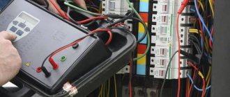
Insulation resistance measurements are carried out using a megaohmmeter, and testing of equipment with the supply of increased voltage of industrial frequency or rectified voltage in electrical installations up to and above 1 kV is carried out only by a team of two people or more, with an electrical safety approval group from the work manufacturer - not lower than fourth ( IV), a team member must have a third group (III) in electrical safety (ES), a person guarding the workplace is allowed a second (II) group in ES. All tests of electrical equipment performed using a mobile unit are carried out according to order. Admission to work in an electrical installation is carried out by operational personnel, and outside electrical installations by the responsible work manager or work performer. If the voltage in the installation is below 1 kV, the measurement still requires two workers, one of whom must have an electrical safety clearance of at least group three. Insulation resistance measurement can be carried out by one worker with a third electrical safety group. The rotor of a working generator in terms of measuring insulation resistance is checked by two workers of the third and fourth electrical safety groups. After connecting the megaohmmeter to live parts, it is necessary to remove the grounding. Grounding is necessary to remove the charge from live parts.
In accordance with the regulatory document “Rules on labor protection during the operation of electrical installations” (POT), the list of measures for measuring the insulation resistance of electrical equipment is determined by the person issuing the order or order. The frequency of tests and the minimum permissible value of insulation resistance must correspond to those specified in the regulatory documents: Scope and standards of testing of electrical equipment (OiNIE, RD (SO) 34.45-51.300-97), Rules for the construction of electrical installations (PUE), Rules for the technical operation of consumer electrical installations (PTEEP). GOST R 50571.16-99 also specifies the standardized values of insulation resistance of electrical installations.
It is important that the temperature conditions and humidity levels acceptable when measuring resistance are observed: the insulation temperature should not rise above +35 degrees Celsius and fall below +5 degrees. The degree of humidity is calculated using the formula Kabs = R60/R15, where R60 is the measured insulation resistance 60 seconds after applying the megoohmmeter voltage, R15 – after 15 seconds. The ratio of these two quantities is called the absorption coefficient. The practice of measuring the insulation resistance of electrical equipment shows that the optimal air humidity to achieve an absorption coefficient that differs from factory values by no more than 20% should be no higher than 80%. The absorption coefficient should not exceed 1.3 (standardized in PTEEP) at temperatures from +10 to +30 degrees Celsius. If, according to measurement results, electrical equipment has an absorption coefficient below 1.3, it must be dried.
The insulation resistance of electrical installations is measured using digital meters with voltage conversion, or generator-type megaohmmeters. Annual verification of devices is carried out by the bodies of the State Standard of the Russian Federation, in St. Petersburg - FGU Test - St. Petersburg, or VNIIM named after. D.I. Mendeleev about which verification certificates are issued. If the check is not carried out on time, the device is not allowed to be used. Measuring the insulation resistance of group cable lines of electrical wiring is carried out with 1 kV megaohmmeters for main cables - for a voltage of 2.5 kV. To measure the insulation resistance of electrical equipment after installation, the voltage values of the megohmmeter (0.5 or 1 kV) are indicated in the ND PUE, chapter 1.8 in tab. 1.8.34. A conclusion about the unsuitability of the wiring is made if, after measuring the insulation resistance, it turns out that the resistance is less than the standardized value.
Documentation
After completing the inspection, all measurements must be reflected in a special document. It must, in particular, include the following information:
- The date the check was performed.
- Amount of work completed.
- Information about the employees who carried out the inspection.
- It is necessary to indicate which device the measurements were used with.
- Connection diagram in accordance with which the work was carried out.
- It is necessary to reflect the conditions for performing the check. For example, it is necessary to indicate at what temperature the measurements were carried out.
- A table is compiled in which it is necessary to reflect that exactly this insulation resistance was obtained during the measurements.
Having such a document will be useful, for example, in the event of an emergency. It will indicate that all necessary operating conditions have been met. The document confirming the measurements must be certified by the signature of the inspector and the employee who carried out the inspection.
What it is
A megohmmeter is a specially designed ohmmeter for testing resistance. The requirement of state standards for the safety of electrical installations requires testing for insulation strength before putting electrical equipment into operation, as well as when servicing it by electrical personnel. For this purpose, meggers are used that provide high DC voltage from 500 V to 5 kV and even 15 kV in accordance with the specified current capacity. Acceptable parameters for insulator resistance are from 1 to 10 MOhm, depending on operating conditions.
What is a megohmmeter
The megohmmeter has the following elements:
- In mechanical devices, the dynamo, triggered by the meter by rotating the handle with a permitted frequency of 2 rps, creates voltage.
- Electronic devices are powered from sources: network, battery devices. They work using Ohm's law. The current passing between 2 switched on points is measured, for example, 2 cable cores, core and ground, or other connection options.
- Measurements are carried out using the reference voltage initially specified in the electrical equipment maintenance schedules.
- The device uses voltage and current, and based on them calculates the insulation resistance.
- The generator produces constant voltage.
- The device has the ability to change the testing ranges with a toggle switch that switches different resistances that change the measurement mode and the outgoing voltage.
When should an inspection be carried out?
When using electrical equipment, you must be sure that it is functional and completely safe. To do this, it is necessary to regularly check the insulation resistance. Usually the time for it comes in the following situations:
- Immediately after production of the product.
- Before installation work begins.
- When putting the facility into operation.
- After an emergency has occurred.
- If serious defects are detected.
- In connection with the performance of maintenance within the time limits provided for by regulatory documents.
Failure to meet deadlines will increase the risk of problems occurring. Typically, enterprises draw up plans for such work in advance. For cables used outdoors, these measures are carried out annually, and for cables used indoors - once every three years.
Measurements with a megohmmeter
When starting to check the cable insulation with a megohmmeter, you need to determine what type of wire you are testing. The description of the sequence of work for different types of cables is similar, but for each group there are certain nuances.
Measuring high voltage lines
This includes wires with voltages of more than a thousand volts. According to standards, the insulation of such products must have a resistance exceeding 1000 MOhm. The device used for measurements must be designed for 2500 V (similarly for low-voltage cables).
Testing of low voltage cables
For such cables, the indicator should be at least 0.5 MOhm. First, the device is placed between the phase conductors, then - between the phases and zero, after that (if the wire has five conductors) - between the phases and grounding, at the very end - between the grounding and neutral conductors (the latter must be disconnected from the bus before this).
Testing of control cable systems
Devices of 500-2500 V are used here. The final result should be more than 1 MOhm. The output of the device is placed on one core, the remaining ones are connected and placed on the ground. The second output is placed on any core that is not subject to measurement at the moment. Having made the measurements, the vein is placed with the others and the next one begins to be tested.
Preparing for work
Before you check the resistance of any cable, you must make sure that there is no voltage on it. For high-voltage lines, a high-voltage indicator is used, for low-voltage lines, protective means are used for manipulations in electrical installations. Warning posters must also be posted.
Video lessons
First of all, we present to your attention the operating instructions for the pointer megohmmeter ES0202/2-G:
Another popular dial meter, which is an analogue of the above model, is the m4100. Using it is also quite simple, as you can see by watching this video:
Digital megohmmeters with display are even easier to use. For example, you can measure cable insulation resistance with a modern UT512 UNI-T meter using the following technology:
Well, the last instruction concerns another popular device - E6-32. The video below shows in sufficient detail how to use a megohmmeter to measure the insulation resistance of a transformer, cable, and even metal communications:
This is the method used to measure insulation resistance with a megohmmeter. As you can see, using this device is not difficult, but you need to take safety precautions seriously and take all necessary protective measures.
It will be interesting to read:
Despite the fact that the megohmmeter is considered a professional measuring device, in some cases it can also be in demand at home. For example, when you need to check the condition of electrical wiring. Using a multimeter for this purpose will not allow you to obtain the necessary data; at most, it is capable of detecting the problem, but not determining its scale. That is why measuring insulation resistance with a megohmmeter remains the most effective test method; this is described in detail in our article.
Operating principle of the device
The megohmmeter generates voltage with its own high-voltage converter, and the milliammeter records the current in the measured circuit. From the school physics course we know Ohm's law, and the relationship between resistance R, which is equal to U divided by I.
Currently, digital measuring instruments have become widespread due to their compactness and lightness, but pointer models with a manual dynamo are still used along with them. Now we will look at how to properly use an old-style and a new megaohmmeter.
Please note that some people call the device for measuring insulation resistance a megohmmeter. This is not quite the correct name, because... if the word is broken down into parts, you get the prefix “mega”, the unit of measurement “Ohm” and “meter” (translated from Greek as measure).
Safety rules when working with a megohmmeter
Since these devices can generate very high voltage, measuring operations must be carried out by a pair of workers, at least one of whom must have a fourth electrical safety clearance group. Without proper training, using such equipment is dangerous - the user may receive an electric shock.
Connecting a megohmmeter to the line being tested
Probes with single tips are inserted into the socket connectors corresponding to the line and ground. A binary probe is used when it is necessary to eliminate leakage currents: one end is placed in the line socket, and the other, marked “E,” in the screen.
The device is connected to the line using terminals. In order to find out the resistance of the insulating material, both probes are placed on bare sections of the wires.
Measurements
When performing measurements, the technician should not touch unprotected sections of wires and other circuit components, as well as the output terminals of the measuring device. You cannot carry out work without first checking the absence of voltage on the cable cores (this can be done with a special tester).
Important! Under no circumstances should work be performed without first eliminating the residual charge from the equipment. This is done through portable grounding, applying it to live components. The residual charge must also be removed after each measurement.
Design and principle of operation of a megohmmeter
The aging of electrical wiring insulation, like any electrical circuit, cannot be determined with a multimeter. Actually, even with a rated voltage of 0.4 kV on the power cable, the leakage current through microcracks in the insulating layer will not be so large that it can be detected by standard means. Not to mention measuring the resistance of intact cable insulation.
In such cases, special devices are used - megohmmeters, which measure the insulation resistance between the motor windings, cable cores, etc. The principle of operation is that a certain voltage level is applied to the object and the rated current is measured. Based on these two values, the resistance is calculated according to Ohm's law (I = U/R and R=U/I).
It is typical that megohmmeters use direct current for testing. This is due to the capacitance of the measured objects, which will pass alternating current and thereby introduce inaccuracies in the measurements.
Structurally, megaohmmeter models are usually divided into two types:
- Analogue (electromechanical) - old-style megohmmeters. Analog megohmmeter
- Digital (electronic) – modern measuring devices.
Electronic megohmmeter
Let's consider their features.
Electromechanical megohmmeter
Let's consider a simplified electrical circuit of a megohmmeter and its main elements
Simplified diagram of an electromechanical megohmmeter
Designations:
- A manual DC generator, a dynamo is used as such. As a rule, to obtain a given voltage, the rotation speed of the hand generator handle should be about two revolutions per second.
- Analog ammeter.
- An ammeter scale calibrated to indicate resistance measured in kiloohms (kOhm) and megaohm (MOhm). The calibration is based on Ohm's law.
- Resistance.
- KOhm/Mohm measurement switch.
- Clamps (output terminals) for connecting test leads. Where “Z” is the ground, “L” is the line, “E” is the screen. The latter is used when it is necessary to check the resistance against the cable shield.
The main advantage of this design is its autonomy; thanks to the use of a dynamo, the device does not require an internal or external power source. Unfortunately, this design has many weaknesses, namely:
- To display accurate data for analog instruments, it is important to minimize the mechanical impact factor, that is, the megohmmeter must remain stationary. And this is difficult to achieve by rotating the generator handle.
- The displayed data is affected by the rotational uniformity of the dynamo.
- Often the measurement process requires the efforts of two people. Moreover, one of them performs purely physical work - he rotates the handle of the generator.
- The main disadvantage of the analog scale is its nonlinearity, which also negatively affects the measurement error.
Note that in later analog megohmmeters, manufacturers abandoned the use of a dynamo, replacing it with the ability to operate from a built-in or external power source. This made it possible to get rid of characteristic shortcomings; in addition, the functionality of such devices has significantly increased, in particular, the voltage calibration range has expanded.
Modern analog model of megaohmmeter F4102
As for the principle of operation, it has remained unchanged in analog models and consists of a special gradation of the scale.
Electronic megohmmeter
The main difference between digital megohmmeters is the use of a modern microprocessor base, which can significantly expand the functionality of the devices. To obtain measurements, just set the initial parameters and then select the diagnostic mode. The result will be displayed on the information board. Since the microprocessor makes calculations based on operational data, the accuracy class of such devices is significantly higher than that of analog megohmmeters.
Separately, mention should be made of the compactness of digital megohmmeters and their versatility, for example, testing residual current devices, measuring ground resistance, phase/zero loops, etc. Thanks to this, comprehensive tests and all necessary measurements can be carried out with one device.
Read also: Varistor markings on the housing
Step-by-step instructions for measuring insulation resistance with a megohmmeter
Despite the fact that using a megohmmeter is not difficult, when testing electrical installations it is necessary to adhere to the rules and a certain algorithm of actions. To search for insulation defects, a high level of voltage is generated, which can pose a danger to human life. Safety requirements during testing will be considered separately, but for now we will talk about the preparatory stage.
Preparation for testing
Before testing the electrical circuit, it is necessary to de-energize it and remove the connected load. For example, when checking the insulation of home wiring in an apartment panel, it is necessary to turn off all AVs, RCDs and differential circuit breakers. The plug connections should be opened, that is, electrical appliances should be disconnected from the sockets. If lighting lines are tested, light sources (lamps) should be removed from all lighting fixtures.
The next step in the preparatory stage is the installation of portable grounding. With its help, residual charges are removed from the circuit under test. It is not difficult to organize portable grounding; for this we need a stranded conductor (necessarily copper), the cross-section of which is at least 2.0 mm 2. Both ends of the wire are freed from insulation, then one of them is connected to the grounding bus of the electrical panel, and the second is attached to the insulating rod; in the absence of the latter, you can use a dry wooden stick.
The copper wire must be attached to the stick in such a way that it can touch the current-carrying lines of the circuit being measured.
Connecting the device to the line under test
Analog and digital megohmmeters are equipped with 3 probes, two ordinary ones, connected to the “Z” and “L” sockets, and one with two tips for the “E” contact. It is used when testing shielded cable lines, which are practically not used in everyday life.
To test single-phase household wiring, we connect single probes to the appropriate sockets (“ground” and “line”). Depending on the test mode, we attach alligator clips to the wires being tested:
- Each wire in the cable is tested against the other wires that are connected together. The wire under test is connected to the “L” socket, the remaining wires connected together to the “Z” socket. A similar connection diagram is shown in the figure.
Connecting a megohmmeter
If the indicators meet the standard, then testing can be completed, otherwise testing continues.
- Each of the wires is tested relative to ground.
- Each wire is checked in relation to other wires.
Test algorithm
Having considered all the main stages, you can proceed directly to the order of actions:
- Preparatory stage (fully described above).
- Installation of portable grounding to remove electrical charge.
- The voltage level is set on the megohmmeter; for household wiring - 1000.0 volts.
- Depending on the expected result, the resistance measurement range is selected.
- Checking the de-energization of the tested object, this can be done using a voltage indicator or a multimeter.
- Special crocodile probes of the measuring wires are connected to the line.
- Disconnecting portable grounding from the tested object.
- High voltage is supplied. In electronic megohmmeters, to do this, just press the “Test” button; if you are using an analog device, you should rotate the dynamo handle at a given speed.
- We read the device readings. If necessary, the data is entered into the measurement protocol.
- We remove residual voltage using portable grounding.
- We disconnect the measuring probes.
To measure the condition of other current-carrying conductors, the procedure described above is repeated until all elements of the object are checked, that is, we are talking about the end of measurements when testing electrical equipment.
Based on the test results, a decision is made on the possibility of operating the electrical installation.