If you want to assemble a long-range WiFi antenna, then you should know about some of its features.
The first and simplest: large antennas of 15 or 20 dBi (isotropic decibels) are the maximum power, and there is no need to make them even more powerful.
Here is a clear illustration of how, as the antenna power in dBi increases, its coverage area decreases.
It turns out that as the antenna’s operating distance increases, its coverage area decreases significantly. At home, you will have to constantly catch a narrow band of signal coverage if the WiFi emitter is too powerful. Get up from the couch or lie down on the floor, and the connection will immediately disappear.
This is why home routers have conventional 2 dBi antennas that radiate in all directions—they are most effective over short distances.
Directed
9 dBi antennas only work in a given direction (directional) - they are useless in a room, they are better used for long-distance communications, in the yard, in the garage next to the house. The directional antenna will need to be adjusted during installation to transmit a clear signal in the desired direction.
Now to the question of carrier frequency. Which antenna will work better at long range, 2.4 or 5 GHz?
Now there are new routers operating at double the frequency of 5 GHz. These routers are still new and are good for high-speed data transfer. But the 5 GHz signal is not very good for long distances, as it fades faster than 2.4 GHz.
Therefore, old 2.4 GHz routers will work better in long-range mode than new high-speed 5 GHz ones.
How Google Authenticator two-factor authentication works
Google Authenticator for desktop adds security to your account with an additional sign-in step. To use the service, you need to register an account and enable the function. To implement the service, an application is used that is installed on mobile platforms, but this is not necessary. The program is necessary to enter the identifier code, it comes to the smartphone and consists of 6-8 digits.
The standard login form involves using a login and password, but when using the Authenticator application, an additional step for identification is required - connecting with a registered smartphone. This method works for a PC, but for a mobile device you need to generate a unique password, which will allow you to log into your profile. Code generation will be required not only for devices, but also for all applications.
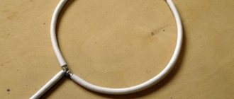
Drawing of a double homemade biquadrat
The first examples of homemade WiFi signal distributors appeared back in 2005.
The best of them are the biquadrate designs, which provide a gain of up to 11–12 dBi, and the double biquadrate, which has a slightly better result of 14 dBi.
According to usage experience, the biquadrate design is more suitable as a multifunctional emitter. Indeed, the advantage of this antenna is that with the inevitable compression of the radiation field, the signal opening angle remains wide enough to cover the entire area of the apartment when installed correctly.
All possible versions of a biquad antenna are easy to implement.
Required Parts
- Metal reflector—a piece of foil-textolite 123x123 mm, a sheet of foil, a CD, a DVD CD, an aluminum lid from a tea can.
- Copper wire with a cross section of 2.5 mm2.
- A piece of coaxial cable, preferably with a characteristic impedance of 50 Ohms.
- Plastic tubes - can be cut from a ballpoint pen, felt-tip pen, marker.
- A little hot glue.
- N-type connector - useful for conveniently connecting an antenna.
Emitter manufacturing
For the 2.4 GHz frequency at which the transmitter is planned to be used, the ideal biquadrate size would be 30.5 mm. But still, we are not making a satellite dish, so some deviations in the size of the active element are acceptable - 30–31 mm.
The issue of wire thickness also needs to be considered carefully. Taking into account the selected frequency of 2.4 GHz, a copper core must be found with a thickness of exactly 1.8 mm (section 2.5 mm2).
From the edge of the wire we measure a distance of 29 mm to the bend.
We make the next bend, checking the outer size of 30–31 mm.
We make the next inward bends at a distance of 29 mm.
We check the most important parameter of the finished biquadrat - 31 mm along the center line.
We solder the places for future fastening of the coaxial cable leads.
Tips and safety precautions
Homemade gun antenna for the Internet: diagrams and drawings
When making such precision equipment as a microwave antenna, it is recommended to take note of a few tips:
- Tip 1. When working with copper wire, when creating bends, you need to operate not with the external, but with the internal value of the length of the biquadrate edge described in this article - Lin = 30.5 - 3.6 = 26.9 (mm). With a tolerance of 0.5 mm, this value can be rounded to 27 mm. Also, to ensure verification, it is better to create a template drawing, for example, for a device, on a real scale, drawn with lines 1.8 mm thick, and then, by applying the future antenna to it, check the manufacturing accuracy.
- Tip 2. If the wire initially has small bends (waves), do not try to straighten it with pliers, this will not lead to the desired result. Instead, you need to find a wooden block and fix it on the table (clamp, screws, etc.). Put on fabric gloves and, stepping back from the edge of the wire 30 - 40 cm, firmly grasp it. The end must be taken with pliers, then from the beginning to the gripping point, bending the wire over the edge of the beam, pull it several times with force (in one direction). With this method, all minor irregularities will be completely eliminated. If the length of the leveled area is not enough, you need to repeat the procedure from the end of the leveled area and above, but placing pieces of hardboard between the jaws of the pliers so as not to scratch the copper.
- Tip 3. In the case when galvanized steel is used, soldering of elements must be done using soldering acid. If aluminum was chosen as the material, connections are made using rivets or threads (bolts and nuts), soldering this metal at home without specialized equipment is impossible.
- Safety precautions when carrying out installation and soldering work. The first thing to remember is that when working with metals you need to use safety glasses. If you plan to use machines with rotating elements (emery wheel), the use of gloves is strictly prohibited. Sleeves should be no longer than elbow length, and hair should be tied back with an elastic band or beret. The second important rule is compliance with standards when performing soldering. The room where work is carried out must be well ventilated. The use of safety glasses is mandatory. When rosin, flux or acid is exposed to high temperatures, vapors are formed that can enter the lungs, so it is advisable to use a tight-fitting respirator with carbon filters.
Reflector
The main task of the iron screen behind the emitter is to reflect electromagnetic waves. Correctly reflected waves will superimpose their amplitudes on the vibrations just released by the active element. The resulting amplifying interference will make it possible to propagate electromagnetic waves as far as possible from the antenna.
To achieve useful interference, the emitter must be positioned at a distance that is a multiple of a quarter of the wavelength from the reflector.
The distance from the emitter to the reflector for biquad and double biquad antennas is found as lambda / 10 - determined by the features of this design / 4.
Lambda is a wavelength equal to the speed of light in m/s divided by the frequency in Hz.
Wavelength at a frequency of 2.4 GHz is 0.125 m.
By increasing the calculated value five times, we obtain the optimal distance - 15.625 mm.
The size of the reflector affects the antenna gain in dBi. The optimal screen size for a biquad is 123x123 mm or more, only in this case can a gain of 12 dBi be achieved.
The sizes of CDs and DVDs are clearly not enough for complete reflection, so biquad antennas built on them have a gain of only 8 dBi.
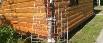
Below is an example of using a tea jar lid as a reflector. The size of such a screen is also not enough, the antenna gain is less than expected.
The shape of the reflector should only be flat. Also try to find plates that are as smooth as possible. Bends and scratches on the screen lead to the dispersion of high-frequency waves due to disruption of reflection in a given direction.
In the example discussed above, the sides on the lid are clearly unnecessary - they reduce the signal opening angle and create scattered interference.
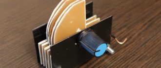
Once the reflector plate is ready, you have two ways to assemble the emitter on it.
- Install the copper tube using soldering.
To fix the double biquadrat, it was necessary to additionally make two stands from a ballpoint pen.
- Secure everything to the plastic tube using hot glue.
We take a plastic box for discs for 25 pieces.
Cut off the central pin, leaving a height of 18 mm.
Use a file or file to cut four slots in the plastic pin.
We align the slots to the same depth
We install the homemade frame on the spindle, check that its edges are at the same height from the bottom of the box - about 16 mm.
Solder the cable leads to the emitter frame.
Taking a glue gun, we attach the CD to the bottom of the plastic box.
We continue to work with a glue gun and fix the emitter frame on the spindle.
We fix the cable on the back of the box with hot glue.
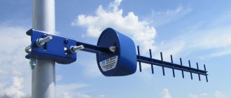
Wi-Fi antenna - gun
This version of the transmitter is very powerful, like a real gun. The antenna-gun can resemble a space blaster, and by analogy with this fantastic weapon, it has a directional and very strong effect.
It is the directionality to one point, as the basic principle of operation of a Wi-Fi antenna, that allows for a fairly large distance of reception and transmission of signals, since there is a high concentration of pulses in one direction.
To make such a device yourself, prepare:
- long metal pin;
- 18 nuts of the corresponding diameter;
- metal sheet, for example copper;
- Wi-Fi adapter (however, you can connect an already installed router).
Instructions on how to make a powerful Wi-Fi antenna will be as follows:
- take a metal sheet and mark the centers of each circle (seven circles in total, the first with a diameter of 9 cm, the second 6.8 cm, the third 5.4 cm, the fourth 3.8 cm, the remaining three - 3.7 cm);
- drill the center (the diameter of the resulting holes should be slightly larger than the diameter of the stud);
- using a compass, draw circles on the metal and carefully cut them out;
- cut off the excess from the hairpin, leaving a length of 18 - 22 cm;
- place the circles on the stud one by one and secure them with nuts;
- in the last two circles, drill holes for the cable;
- we tin the disks;
- pass the cable through the hole in the last circle and solder the shielding winding to the metal;
- pass the middle core of the cable through the hole in the second disk and solder it;
- Screw the existing Wi-Fi adapter to the output of the connector.
Before starting work, carefully study the photo of a Wi-Fi antenna of this type. This will make it easier for you to understand the essence of the whole process.
A powerful antenna-gun is ready for use, install it on a window and receive signals from a very long distance.
Connecting to a router
Those who have experience can easily solder to the contact pads on the circuit board inside the router.
Otherwise, be careful, thin traces may come off the printed circuit board when heated for a long time with a soldering iron.
You can connect to an already soldered piece of cable from a native antenna via an SMA connector. You shouldn't have any problems purchasing any other N-type RF connector from your local electronics store.
About the range of Wi-Fi antennas
From a native router antenna of 2 dBi, a 2.4 GHz signal of the 802.11n standard can spread over 400 meters within line of sight. Signals of 2.4 GHz, old standards 802.11b, 802.11g, travel worse, having half the range compared to 802.11n.
Considering a WiFi antenna to be an isotropic emitter - an ideal source that distributes electromagnetic energy evenly in all directions, you can be guided by the logarithmic formula for converting dBi to power gain.
Isotropic decibel (dBi) is the antenna gain, determined as the ratio of the amplified electromagnetic signal to its original value multiplied by ten.
AdBi = 10lg(A1/A0)
Conversion of dBi antennas into power gain.
| A,dBi | 30 | 20 | 18 | 16 | 15 | 14 | 13 | 12 | 10 | 9 | 6 | 5 | 3 | 2 | 1 |
| A1/A0 | 1000 | 100 | ≈64 | ≈40 | ≈32 | ≈25 | ≈20 | ≈16 | 10 | ≈8 | ≈4 | ≈3.2 | ≈2 | ≈1.6 | ≈1.26 |
Judging by the table, it is easy to conclude that a directional WiFi transmitter with a maximum permissible power of 20 dBi can distribute a signal over a distance of 25 km in the absence of obstacles.
A further increase in antenna power is unreasonable; the signal will propagate in too narrow a disk-shaped zone.
Author: Vitaly Petrovich, Ukraine, Lisichansk
How to connect
Connecting any antenna occurs in several stages:
- The first thing you need to do is find the most suitable place for installation. If everything is clear with the internal device, you can install it on a windowsill, closer to the window, but the external one should be on the roof of the building or in another elevated place so that it can be directed as accurately as possible to the access point. In addition, it must be fixed vertically or horizontally, depending on the type;
- After this, you need to connect the external product to the amplifier, if provided by the design, or directly to the laptop;
- You need to connect the mobile signal amplifier to power.
- Test the received signal in the laptop. The number of communication divisions should be maximum in all places where the operating range extends.