SHARE ON SOCIAL NETWORKS
FacebookTwitterOkGoogle+PinterestVk
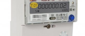
From this article you can learn the features of such a device as a two-tariff electricity meter: the main types of designs, their advantages and disadvantages, purchase prices. The text describes the procedure for installing the device and related formalities, rules for handling the meter, checking it and taking readings. The article examines in detail devices with different numbers of phases and recommendations for calculating energy consumption.
Two-tariff meters can be single- and multi-phase
Stages of work
The test is carried out using a multimeter or a special screwdriver. Only after this can you continue working.
Installation steps:
- Mark the location of the meter. The height above the floor level should not be less than 1.6 m.
- Label the wires so you don't have to worry about searching for what you need during installation.
- Drill places for fastening. Be sure to check the level of the horizontal installation.
- To prevent the circuit from being disrupted, the electric meter is connected first. Using clamps, other modular equipment is installed: RCDs, automatic devices and differential automatic devices.
- The power cable and load cable are inserted. When installing the meter outdoors, use special seals to prevent moisture and dust from entering.
- Use a knife to separate the ends of the wires. Trimming is carried out in such a way that the insulation is not damaged.
- Check the phase when connecting the input wire to the switch. Turn on the power supply and use a multimeter to check that the voltage is 220 V.
- Then the input cable is connected to the input machine. The phase cable is inserted into the upper left contact, the neutral cable into the right. Grounding is connected to the terminal. Tighten the contacts and repeat the procedure after a few minutes.
- The electricity meter is connected to the machine.
- Make jumpers from the wire and label them. The cable must be inserted only with the part free from the heat-shrinkable tube. After this, screeding is carried out in two stages.
- Then the voltage is connected to the machine and the buses.
If everything is done correctly, invite a specialist to seal it. Based on the results, the inspection person must issue a corresponding act.
Despite the ease of installation and installation of the electric meter, it is still better to turn to professionals: in addition to the necessary experience and knowledge, they have special equipment and materials.
Watch the video, which shows in detail the steps for connecting a single-phase electricity meter:
Rules
The rules for installing an electric meter in a private house recommend installing it on the border of the balance sheet boundaries. This could be a wall of a house, a fence, or a separate support running along the border of the site.
The location is determined by the design organization together with the owner. It should not contradict the rules for operating electrical installations (PUE) and Government Decree No. 530. It states that the owner is obliged to provide the inspector with free access to the meter. According to the PUE and the project, the owner is obliged to comply with the conditions for installing the electrical box.
PUE 7 clause 1.5.29 prescribes the height of the electric meter. It should be within 0.8 - 1.7 meters from the ground. In exceptional cases, installation of the box at a height of 0.4 m is allowed.
In this case, the box must be designed for outdoor use. And the operating conditions of the meter must correspond to its location.
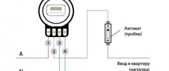
Typical single-phase network input circuit
However, from all the connection diagrams for a single-phase meter, you need to choose the one that is suitable for a particular case. The differences are expressed in the following factors:
- There is no input for grounding.
- There is no input machine in front of the counter.
- There is no disconnect switch.
- Branching of contours is not provided.
- Availability and type of protective device.
Connecting an electric meter according to the diagram
Connecting a meter without automatic devices and an RCD is impractical. A voltage surge, circuit overload, or short circuit will lead to the failure of all consumers powered in the power supply system. Therefore, protection is mandatory, especially since automatic opening devices are inexpensive.
How to switch to multi-tariff electricity metering
In order to take advantage of this tariff, you will need not only the two-tariff meter itself, that is, an electric meter, but also registration of this service with the electricity supplier. To do this you need:
- Go to the organization that is your supplier.
- Contact the department for drawing up electricity supply contracts and make sure that it is possible to switch to two-tariff metering.
- Write an application to switch to a new tariff.
- Pay the cost of removing the old meter, the cost of a new one with installation, connection and configuration.
A set of tools and materials required for installation
In order to begin installing the meter and installing the corresponding electrical part, you must acquire the following materials and tools:
- An electricity meter, i.e. the device itself that will be installed;
- A subscriber panel, which is designed for storing installed equipment;
- A set of tools with handles with insulating properties;
- Voltage indicator (pointer);
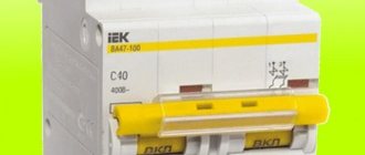
- DIN - rails used for fixing (circuit breakers);
- Automatic switches;
- Electrical wires, which will subsequently serve to connect system elements;
- a set of nuts and screws;
- insulators.
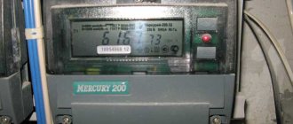
Induction (mechanical) electricity meters
They are a group of well-known electricity meters equipped with a rotating wheel, which is installed inside the body of the electrical appliance. The faster it rotates, the more energy consumption increases. To display information about meter readings, special reels with numbers are used.
Single-phase induction type meter
Structurally, induction meters consist of the following elements:
- Voltage coils used to limit the level of alternating current. Protects the electronic device from the negative effects of interference created by third-party sources, and also generates a magnetic flux commensurate with the voltage;
- A current coil that creates a level of alternating magnetic flux commensurate with the current;
- Counting mechanism in the form of a worm gear;
- Aluminum disk;
- A permanent magnet that creates smooth movement of the disk.
Operating principle of an induction energy meter
When connected to the network, the current and voltage coils create magnetic fluxes that pass through the surface of the aluminum disk. It is worth noting that the flux created by the current coil is different from the flux that comes from the voltage coil with its U-shape, due to which it pierces the disk several times. As a result of the influence of flows, forces of an electromechanical nature are formed that set the disk in motion.
D - disk, M - magnet, 2 - disk axis, upper coil (voltage), and lower current coil
Then the axial side of the disk interacts with a counting mechanism made using a worm (gear-screw) transmission principle, which ensures the transmission of the necessary information signals to the digital reels.
A ring with a toothed rim on top, on which a “worm” is put on, equipped with torque elements
Over time, the signal power level decreases and at this moment the permanent braking magnet begins to work, leveling out the frequency fluctuations of the disk rotation. This occurs as a result of interaction with vortex-type flows. During its operation, the magnet creates an electromechanical force that is inverse to the torsion of the disk, which helps reduce the speed of the disk or stop it completely.
Representatives of this group of electricity control and metering devices were widely used during the Soviet Union, however, even now similar devices are installed in most apartments. Such popularity and demand is determined by the simple design and low cost of the devices.
Advantages and disadvantages of induction type meters
Advantages:
- High reliability;
- Long service life (about 20 years);
- High stability of operation (no dependence on voltage drop in the network);
- Low cost.
Flaws:
- Low accuracy class (ranging from 2 to 2.5 units);
- High level of current consumption for self-sufficiency;
- Increased reading error at low load;
- Impossibility of simultaneous accounting of active and reactive types of electricity;
- Unidirectional energy metering;
- Large dimensions.
In the process of collecting information about the performance and analyzing the shortcomings of induction meters, design engineers (power engineers) developed a more advanced and reliable type of electricity metering devices, which was called electronic.
Connecting a single-phase electric meter with a diagram
Installing an electricity meter using a single-phase circuit is the simplest of the connection options, since the maximum number of wires used for installation is 6 pieces, not including the load one. The input circuit of the meter with this connection method consists of the following wires: phase wire (F), working “zero” wire (N) and, if there are protective ground wires (PE). The same thing will happen in the output circuit of the counter.
Single-phase meter connection
Step-by-step instruction
- We mount the meter into the panel body using fasteners (screws with nuts) that are included with the panel.
- We fix the machines using special latches (installed on them) on the surface of the DIN rail - a 35 mm curved plate. After this, we mount the resulting structure and secure it to the support insulators using screws.
- We install the busbars intended for fastening the protective and grounding wires onto the support insulators, securing them to the DIN rail using connecting elements. Do not forget to maintain some distance between them in order to prevent the possibility of a short circuit between the wires.
- We connect the loads: we connect the phase wire (F) to the lower terminals of the machines, and the grounding and working “zero” wires to the corresponding busbars.
- We connect the upper terminals using jumpers - you can buy them in a store - or make them yourself from the remnants of the wire used during installation, after first removing the insulation layer (about 1 cm).
- We connect the device to the loads: we connect the third terminal of the device - the “phase” output - to the upper line of terminals of the machines (or with one of them, using a jumper), the fourth terminal of the meter - the “zero” output - we connect to the zero bus.
- Before connecting the meter to the network, we determine the wires by type (phase, neutral, protective). In the event that there is no neutral wire to determine the phase one, touch them with the wire connected to the indicator, and it will show where the phase is located. If there is a protective ground, it can be detected by the green wire.
- After determining the types of wires, we de-energize the facility into whose network the meter is planned to be connected.
- Then we connect the “phase” wire to the first terminal, and the “zero” wire to the third terminal of the meter.
Video: 1-phase electricity meter connection diagram
https://youtube.com/watch?v=nIA6rT3_fNY
The modern market for electricity monitoring and metering devices provides a wide selection of products, which are divided into several categories. Each of which has advantages and disadvantages. Knowing these parameters, you can choose the most suitable meter for yourself and install it in your home without any problems.
How the meter works
Single-phase and three-phase meters are designed according to the same principle. The only difference is that in a 380 volt network, accounting is carried out separately for each of the phases, and then summed up. Let's figure out how the meter works for one phase, after which it is not difficult to understand the structure of the three-phase one. Below is a block diagram of a modern direct-connect device.
The terminals for connecting the wires are usually located in the order shown in the figure, but it is better to check the passport of a specific meter
Electronic models
Electronic electricity meters can operate in both AC and DC networks
Constant voltage is usually used in enterprises, so it is not too important for apartments and private houses. When compared with electromechanical models, electronic ones are much smaller in size, since they have few large-sized elements
In addition, they are more reliable since there are no moving parts. Electronic ones have one more advantage - they take into account both active and reactive loads (the sum of the inductive and capacitive components).
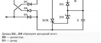
The voltage transformer is connected between phase and zero, the current transformer is connected to the phase conductor gap. Data from the transformers is transmitted to the converter, where it is transformed into frequency signals and sent to the microcontroller. It decrypts the readings and records them in RAM (random access memory). In parallel, the microprocessor controls the electronic relay and display.
Block diagram of an electronic electricity meter
Data in RAM is stored for a long period of time, entries are made like a diary. It records electricity consumption by date and time, which allows for consumption analysis. In some modifications, electronic three-phase meters can transmit information about consumption through a special channel. This channel can be connected to a home computer or smart home system. With certain settings, it can automatically transfer data to the subscriber service for calculations.
Another function of electronic metering devices is multi-tariff metering. If there are several time-dependent tariff schedules, the amount of energy consumed at different times is recorded in different cells. When readings are taken, the data is written off and multiplied by your tariff. Using multi-tariff metering allows you to save on electricity bills.
Electromechanical or induction
Energy metering in induction meters is based on monitoring the parameters of an alternating magnetic field, so such devices can only operate with alternating current.
The device of an induction electromechanical counter
The main element of a 3-phase induction meter is a specially designed magnetic circuit with a slot. The edge of the disk mounted on the axis is inserted into the slot. Current flows through one of the magnetic circuit coils, the second is connected in parallel. A mechanical counter is connected to the plane of the disk using gears, which counts the rotations of the disk.
The current passing through the magnetic circuit creates a magnetic field, and this creates eddy currents in the aluminum disk.
The interaction of the magnetic field and vortex flows creates a torque that causes the disk to spin around its axis. The greater the current, the more powerful the field is generated, the faster the disk rotates, the faster the readings on the meter change. No tags for this post.
Briefly about the main thing
Regardless of who owns the home, the home owner must know how to change the electric meter, follow operating rules, monitor the condition of the device and respond to its malfunctions.
The main stages of accounting replacement are as follows:
- submitting a written application to the energy supply organization;
- taking readings and seals, drawing up a report by a company employee;
- purchasing a new metering device;
- dismantling old and installing new equipment;
- counter sealing.
Attention! The procedure for replacing an electric meter may differ in different regions, so it is recommended to first call the energy supply company to find out all the details and clarify the plan for further action.
Replacing electricity meters is a lengthy process, accompanied by the collection of the required documentation package. By choosing the right device and following the recommendations of specialists, the new device will accurately determine the amount of electricity consumed over time.