Home > Switches and sockets > Load switch in apartments and houses
Conventional circuit breakers are not designed for switching consumers under load. Their task is to protect the circuit from overload and short circuits. A load switch is used to cut off the voltage in an operating network. In fact, it is a switch that serves to turn off industrial equipment, premises, apartments, buildings.
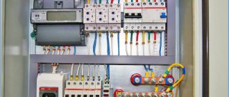
Load switch in panel
Using a load switch, only the rated current of the consumer is switched off. The device is not an automatic protection device, but it can be used to turn off the load manually when an accident threatens. For automatic shutdown, automatic circuit breakers and RCDs are used.
Circuit breaker functions
From the name it is clear that this is a switch that turns off automatically . That is, himself , in certain cases. From the second name - circuit breaker - it is intuitively clear that this is some kind of automatic device that protects something.
Here are examples of the installation and use of such machines - when installing an apartment meter and when replacing electrical wiring in an apartment.
Now more details. The circuit breaker trips and turns off in two cases - in case of overcurrent , and in case of short circuit (short circuit) .
Overcurrent occurs due to faulty consumers, or when there are too many consumers. Short circuit is a mode when all the power of the electrical circuit is spent on heating the wires, while the current in this circuit is the maximum possible. More details will follow.
In addition to protection (automatic shutdown), machines can be used to manually turn off the load. That is, like a switch or a regular “advanced” switch with additional options.
Another important function (this goes without saying) is the connection terminals. Sometimes, even if the protection function is not particularly needed (and it never hurts), the terminals of the circuit breaker can be very useful. For example, as shown in the article Laying the input cable from the gander to the meter.
Load switches
Three-key switch with socket: selection and connection
The load switch serves to switch electrical circuits and has more contacts. The switch can be used to switch one or more networks. It is also called a changeover or transfer switch. With its help you can form a new chain.
In apartments, low-power switches are used to independently control lighting from different places.
Pass-through switch diagram
The figure shows a diagram of connecting two switches to turn on a light bulb from two places. The phase wire is made in brown, and the neutral wire is made in blue. The wires connecting the contacts of adjacent switches to each other are indicated in black. By pressing the key of any switch, you can independently apply voltage to the light bulb or turn it off.
In multi-storey residential buildings, powerful changeover switches are used to put a new supply line into operation when an accident occurs on one of them.
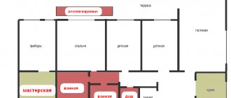
Residential building power supply diagram
If the line (1) fails, a transition to the line (2) is made using changeover switches (3).
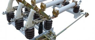
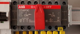
Similar to a circuit breaker, a load switch is capable of carrying a rated load current. The picture below shows popular models that can be purchased on the market for home use. With their help, you can switch the loads of electric boilers, welding machines and other household appliances.
Types of switches available on the modern market
Number of poles
Depending on the number of poles, the machines are:
- Single-pole (1p, 1p). This is the most common type. It stands in a circuit and protects one wire, one phase. This is shown at the beginning of the article.
- Bipolar (2p, 2p). In this case, these are two single-pole circuit breakers, with a combined switch (handle). As soon as the current through one of the machines exceeds the permissible value, both will turn off. These are mainly used to completely disconnect a single-phase load when both the zero and the phase break. It is the two-pole circuit breakers that are used at the entrance to our apartments.
- Three-pole (3p, 3p). Used to break and protect three-phase circuits. Just as in the case of two-pole ones, these are actually three single-pole circuit breakers, with a common on/off handle.
- Four-pole (4p, 4p). They are rare, they are installed mainly at the input of three-phase switchgears (switchgears) to break not only the phases (L1, L2, L3), but also the working zero (N). Attention! Under no circumstances should the protective grounding (PE) wire be broken!
Purpose
High-voltage circuit breakers are installed in substations and switchgears of networks from 6 kV to 10 kV. The most common devices are the VNA (autogas) type. They are the cheapest and have no special requirements. Gases for arc extinguishing in VNA circuit breakers are produced from built-in plastic inserts. This use of gas to protect contacts is typical only for these models. Switching is carried out using a manual drive.
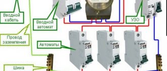
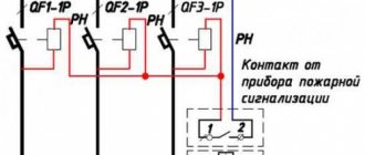
A load switch for household consumers with a voltage of no more than 380 V is used as an input switching device on electrical panels. A power cable is connected to its input, and circuit breakers and RCDs are connected to the output, performing the functions of protection against short circuits, overloads and current leakage to ground.
Circuit breaker current
Automatic currents come from the following series:
0,5, 1, 1,6, 2, 3,15, 4, 5, 6, 8, 10, 13, 16, 20, 25, 32, 40, 50, 63.
The denominations most often used in everyday life are highlighted in bold. There are other denominations, but we won’t talk about them now.
This current for the circuit breaker is rated. If it is exceeded, the switch will turn off. True, not immediately, as stated below:
How to choose a load switch - mini switch
If you already have an incoming circuit breaker installed, to select a load switch, focus primarily on its rated current. It is recommended to select the rating of the load switch either equal to the rated current of the machine, or one step higher. At the same time, we should not forget that the rules dictate us.
Guided by this, purchase devices from 40A and higher in the store, especially since their prices are not too different from their “smaller brothers”. Well, the load switch should definitely be located before the input circuit breaker, or even better, before the meter itself.
Some electricians often use an electrical panel diagram even without an input circuit breaker. This is also permitted if you have properly protected the outgoing lines with separate automatic machines. In this case, just one load switch is mounted at the input.
The advantage of such a scheme is not only savings, but also selectivity. If there is a short circuit in the wiring, you will not have both the input switched off at the same time (extinguishing the entire apartment, which often happens with high short-circuit currents) and the group circuit breaker.
Time-current characteristics
Obviously, the machine does not always turn off instantly, and sometimes it needs to “think and make a decision”, or give the load a chance to return to normal.
The time-current characteristic shows after what time and at what current the machine will turn off. These characteristics are also called tripping curves or current-time characteristics. Which is more precise, since it depends on the current after what time the machine turns off.
Tripping curves or current-time characteristics
Let me explain these graphs. As I said above, the circuit breaker has two types of protection - thermal (against overcurrent) and electromagnetic (against short circuit). In the graph, the operation of thermal protection is a section that smoothly descends. Electromagnetic – the curve abruptly breaks down.
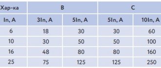
The thermal one works slowly (for example, if the current is twice the nominal value, the machine will go out in about a minute), and the electromagnetic one works instantly. For graph B, this instant “begins” when the current exceeds the nominal value by 3-5 times, for category C - 6-10 times, for D (not shown, since it is not used in everyday life) - 10-20 times.
How it works - you can imagine what will happen if the current exceeds the nominal value by 5 times, and the protection is with the “C” characteristic, as in all houses. The machine will only go off after 1.5-9 seconds, depending on your luck. In 9 seconds the insulation will melt and the wiring will need to be changed. In this case, therefore, short circuit is better than overload.
Classification
- Number of poles:
- Single pole;
- Bipolar;
- Three-pole.
- Presence or absence of current limitation;
- Release device version:
- Thermal – prevents overload;
- Electromagnetic – “notices” a short circuit in the circuit;
- Semiconductor - it is possible to configure against all accidents;
- Combined.
- Drive type:
- Manual;
- Electromagnetic.
- The presence or absence of the ability to adjust the response delay time when a short circuit occurs;
- According to execution form:
- Stationary;
- Roll-out (pull-out) with basket;
- Fixed.
Selecting a circuit breaker. Basic Rule
It is necessary to select a circuit breaker based on the cross-sectional area of the wire that this circuit breaker protects (which is connected after this circuit breaker). And the cross-section of the wire is based on the maximum current (power) of the load.
The algorithm for selecting a circuit breaker is as follows:
- We determine the power and current of the line consumers that will be fed through the machine. The current is calculated by the formula I=P/220 , where 220 is the rated voltage, I is the current in amperes, P is the power in watts. For example, for a 2.2 kW heater the current will be 10 A.
- We select the wire according to the cross-section selection table depending on the current. A cable with a conductor cross section of 1.5 mm² is suitable for our heater. In the worst conditions in a single-phase network, it holds a current of up to 19A.
- We choose a machine so that it is guaranteed to protect our wire from overload. For our case - 13A. If you install a machine with such a rated thermal current, then at a current of 19A (one and a half times higher), the machine will work in about 5-10 minutes, judging by the time-current characteristics.
Is it a lot or a little? Considering that the cable also has thermal inertia and cannot instantly melt, this is normal. But considering that the load cannot just increase its current by one and a half times, and in these minutes a fire can occur - this is a lot.
Therefore, for a current of 10 A, it is better to use a wire with a cross-section of 2.5 mm² (the current with an open installation is 27 A), and a 13 A machine (if it is exceeded by 2 times, it will work in about a minute). This is for those who want to play it safe.
The main rule will be this:
The wire current must be greater than the current of the machine, and the current of the machine must be greater than the load current
Iload < Iaut < Iprov
This refers to maximum currents.
And if there is such a possibility, the rating of the machine should be shifted towards the load current. For example, the maximum load current is 8 Amperes, the maximum wire current is 27A (2.5mm2). The machine should be chosen not for 13 or 16, but for 10 Amperes.
Here is the machine selection table:
Additional elements for air circuit breakers
Features of operation and application of the Tesla resonant transformer
The switch itself cannot generate the compressed air flow on which its operation is based, so the following main components are required for its operation:
- Compressor for creating compressed air;
- Sealed pneumatic drive system;
- Receiver for storing ready-made compressed air.
In connection with the use of these components, also according to GOST, the following is required:
- Pressure gauges. They show the actual pressure in the switch reservoir;
- A minimum pressure switch whose contacts will provide a signal in the event of a decrease in a certain pressure that is normalized. The same role can be played by a pressure gauge containing an electrical contact part;
- General shut-off valve, which is installed on the air duct;
- A check valve that ensures reliable shutoff of the compressed air outlet from the tank when the pressure in the supply air line decreases;
- A filter that cleans the air from various, conductive and other dust;
- A device for draining air or water from the lowest point of the tank.
Table for selecting a circuit breaker based on cable cross-section
The choice of circuit breaker clearly depends on the cable cross-section. If the current of the machine is selected more than necessary, then the cable may overheat due to the flow of high current. If the machine is selected correctly, then if the current exceeds it will turn off and the cable will not be damaged.
Table for selecting a machine according to cable cross-section
Pay attention to the cable routing methods (installation type). Depending on where the cable is laid, the current of the selected circuit breaker may differ by 2 times!
According to the table, we have the initial cable cross-section, and select a circuit breaker for it. For us, as electricians, the first three columns of the table are most important.
Now - how to choose a circuit breaker if the power of the devices is known?
Table for selecting a circuit breaker based on load power
Table of consumption and current of the circuit breaker according to the power of devices
It can be seen that the manufacturer recommends different time-current characteristics for different electrical appliances. Where the load is purely active (different types of heaters), the characteristics of the machine “B” are recommended. Where there are electric motors - “C”. Well, where powerful engines with difficult starting are used - “D”.
The time-current characteristic D is not included in this table because it is not for domestic use. More details about starting engines are described in the article about connecting an electric motor through a magnetic starter. And also about turning on the solid-state relay.
Table of dependence of the current of the circuit breaker (fuse) on the cross-section
And here is how the Germans treat the circuit breaker current depending on the cross-sectional area of the wire:
Table for selecting a circuit breaker for different wire cross-sections
As you can see, the Germans are playing it safe and are providing for a larger reserve compared to us.
Although, perhaps this is because the table was taken from instructions from “strategic” industrial equipment.
Modular automatic machine C40
This article discusses the C40 modular machine. The machine is called a modular machine because each of its poles is a separate standard module. Essentially, the production of multi-pole circuit breakers is carried out by connecting several single-pole modules to each other. Thus, a modular machine differs from other types of machines in the method of manufacturing the body and its assembly. For example, an automatic machine in a molded case is a one-piece monolithic device. It cannot be disassembled into individual poles. Accordingly, it is impossible to assemble a multi-pole machine from several single-pole circuit breakers.
As a rule, the module width is usually 18 mm. However, for some manufacturing companies the width of the machine module may vary. For example, ABB has a machine module width of 17.5 mm. But Siemens has a 17.6mm machine module.
In some series, specialized modular single-pole circuit breakers may be of non-standard width. However, they are still measured in the manufacturer's standard modules. For example, the machine can be 0.5 modules or 1.5 modules wide.
As usual, there is a latch on the back of the MCB. The latch allows you to mount the machines on DIN rails located in the electrical panel.
In principle, a series of modular circuit breakers are available with a rated current of up to 125 amperes. In turn, household series of automatic machines are manufactured for currents up to 63 amperes.
How does a circuit breaker work?
A bonus is the device of the protective circuit breaker, several photos of the circuit breaker, which is given at the beginning of the article.
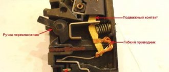
Circuit breaker device. As you can see, the device is not simple. Upper (fixed) contact – right
Circuit breaker. One second before the trash can)
Other switches.
Because In my switchboards I mainly use modules from ABB, but I don’t have many photos of Schneider Electric, Legrand, Hager switches.
I’ll say right away that these manufacturers do not have similar DIN-rail switches like ABB OT63, except perhaps Hager, who have a HAB switch for 20-63A in their product line.
Hager also has modular switches 1-4pole SBN series from 16 to 125A.
In one of the panels I used SBN 2P switches for 63A, which are quite nice, like the entire Hager module.
Schneider Electric also has modular circuit breakers 1P-4P of the iSW series for 20-125A.
I have not yet used Legrand modular switches. I managed either with automatic machines or in 3-phase switchboards with OT63 switches from ABB.
Thank you for your attention.
Download
For those who are interested in the topic deeper and more thoroughly, I am posting GOST, which describes in detail all the characteristics and terminology of circuit breakers.
• GOST R 50345-2010 / GOST R 50345-2010 (IEC 60898-1:2003) Small-sized electrical equipment. Automatic switches for overcurrent protection for household and similar purposes. Part 1. Circuit breakers for alternating current. This standard applies to air circuit breakers (hereinafter referred to as circuit breakers) for alternating current for operation at a frequency of 50 or 60 Hz with a rated voltage (between phases) of not more than 440 V, a rated current of not more than 125 A and a rated breaking capacity of not more than 25,000 A. , pdf, 1.89 MB, downloaded: 1097 times./
• Kharechko V.N., Kharechko Yu.V. Automatic switches of modular design / Kharechko V.N., Kharechko Yu.V. Automatic circuit breakers of modular design: Reference manual. The reference manual sets out the requirements of GOST R 50345-99 (IEC 60898-95) for household circuit breakers intended for overcurrent protection, examines the design of circuit breakers, gives characteristics and their classification. Errors are analyzed that are partially corrected in the new version of GOST R 50345-2010, pdf, 7.17 MB, downloaded: 1103 times./
As always, I will be glad to have questions and comments on the article in the comments!