A circuit breaker or circuit breaker is a switching device that conducts currents under normal conditions in a circuit and automatically turns off the supply of electricity from the mains to the consumer in the event of a short circuit or overload; you can also turn the circuit on and off manually.
The main difference between a two-pole machine and a single-pole one is the presence of the machine both in phase and at zero, that is, on two poles. Moreover, when switching off, both phase and zero are simultaneously disconnected, thanks to the common cocking handle. Used for mounting a single-phase circuit. For a three-phase circuit, you need to use 3- and 4-pole circuit breakers.
Application area
- As introductory circuit breakers. This is the most popular method of application. By simultaneously disconnecting the phase and zero, maximum safety is ensured when working in the circuit, because a complete de-energization occurs. In addition, according to the new rules of Electrical Installations (clause 6.6.28, clause 3.1.18), the operation of single-pole circuit breakers at the input is prohibited.
- To protect a separate group of electricity consumers. Disabling the two-pole circuit breaker will prevent the operation of the RCD (Residual Current Device - designed for protection against differential currents) in the event of erroneous contact between zero and phase during repair work in circuits under load. It also makes it easier to find a branch with a fault when an RCD is triggered by a current leak to the ground.
- For protecting and controlling circuits with simultaneous power supply. For example, when connecting a heat gun, a phase is supplied through one pole of the machine to the heating elements, and through the other pole, a phase is supplied to the fan motor. If one equipment turns off, the other will also turn off, which will prevent the possibility of the heating elements operating without cooling.
Design and principle of operation
The design of a two-pole switch is identical to that of a single-pole circuit breaker. In other words, this device consists of two single-pole circuit breakers combined in one housing. Its peculiarity is that in these protective devices, in emergency situations, both protected lines are automatically switched off simultaneously. In principle, you can make a basic two-pole circuit breaker yourself by tightly connecting the control levers of two single-pole circuits with a bar.
Attention! It is impossible to replace a two-pole circuit breaker with two single switches operating separately! You should also not use single switches connected by a jumper as a two-pole circuit breaker. The design of the two-terminal circuit also includes a locking mechanism, which is not present in the “improved” device of single-pole circuit breakers.
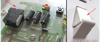
To understand the structure and operating principle of a two-pole circuit breaker, it is enough to understand the structure of a machine with one pole. The simplest such device consists of a bimetallic plate and the design of a charging and releasing mechanism. By the way, the outdated machines looked exactly like this. The design of such a switch is shown in Figure 1.
In situations equivalent to a short circuit or during prolonged overloads in single-phase circuits, the bimetallic plate heats up and, due to deformation, acts on the operating lever of the structure. The protective shutdown mechanism is triggered and the circuit is broken.
Figure 1. Old style circuit breaker
The operating principle of this device is very simple. When the rated currents exceed the permissible parameters, the thermal release actuates the moving contact and the circuit is broken. The power cut-off mechanism can operate in two cases - during an overload or due to a short circuit. To connect the power, it is necessary to eliminate the cause of the operation currents, and then turn on the machine by pressing the control lever.
The operating scheme is simple and reliable. However, it has a significant drawback: the machine does not respond to leakage currents, therefore it cannot protect against electric shock or prevent the wiring from catching fire in the event of sparking. Additional devices are required for complete protection.
Modern two-pole packages do not have this disadvantage. Figure 2 shows the design of such a circuit breaker. Its design has one important detail - an electromagnetic release. Such two-pole devices combine the functions of conventional differential circuit breakers and a residual current device (RCD).
Figure 2. The structure of a modern machine
Thanks to the electromagnetic release, the charging and tripping mechanism of the two-pole circuit breaker reacts to leakage currents. This is the same blocking device discussed above.
Operating principle of an electromagnetic release.
Along a two-wire line, current flows in two opposite directions - along the phase conductor in one direction, and along the neutral conductor in the other. At the rated voltage, the magnetic fluxes in the solenoid coils, induced by equal counter currents, are compensated. Therefore, the resulting magnetic flux is zero.
But as soon as a leak appears, the balance is disrupted, and the resulting magnetic flux will pull the rod into the solenoid. He, in turn, will activate the levers of the cocking and release mechanism. A two-pole circuit breaker will open 2 poles, regardless of which conductor has a leak or short circuit. The RCD will trip as a reaction to changes in the parameters of the differential currents.
Advantages of application over single-pole circuit breakers
Let's consider a situation where someone confused the phase with zero. Then, when the single-pole circuit breaker is turned off, the zero line is disconnected, and the phase remains in the circuit. A person, thinking that he has protected himself by turning off the machine, starts working and receives an electric shock. To prevent this from happening, after disconnecting the single-pole circuit breaker, you need to check the absence of voltage in the circuit with an indicator. But it is still safer to use a two-pole circuit breaker, which will completely de-energize the circuit.
In the case when the RCD has tripped, it is necessary to find a fault in the circuit. First of all, turn off all electrical appliances from the sockets. If this does not produce results, the branches of the circuit are switched off sequentially, but both zero and phase must be disconnected. A single-pole circuit breaker does not provide this opportunity. You will have to remove the zero on the bus, which is problematic, since it requires dialing to find the right wire. A two-pole machine copes with this task perfectly.
Thus, the advantages:
- Safety - the electrical circuit is completely broken.
- Ease of troubleshooting.
Features of the operation of single-pole and double-pole AV
The essence of the work of each of these types, in general, can be understood from the name. A single-pole circuit breaker is designed to disconnect one line. A two-terminal network differs from it in that it controls the working process in two lines simultaneously and compares the parameters of the electron flow, determining whether it corresponds to the value that is permissible for the correct operation of the network. If these indicators are exceeded, the device is triggered, turning off the power to both lines simultaneously.
Some readers may have a question: is it possible to replace a two-pole circuit breaker with a pair of single-pole switches? This should not be done under any circumstances. Indeed, in a device with two poles, its elements are connected not only by a common lever, but also by a locking mechanism.
This means that if a problem occurs, they will turn off simultaneously, and in a pair of single-pole circuit breakers independent of each other, only one circuit breaker will work. In this case, electric current will still be supplied to the faulty circuit through the switched on device, which may cause a fire in the wiring. You can see the attempts at unification in the following video:
The difference between these two types of safety switch lies in the design of the release. A two-pole circuit breaker must have a tripping element, the configuration of which allows both parts of the device to be turned off simultaneously, both during automatic operation and during manual operation.
If the electrical circuit in the apartment is single-circuit, then there is no need to install a two-pole circuit breaker in it, since there is no need to simultaneously protect different segments of the room. But in the case when complex equipment is installed in one of the rooms, which, due to its parameters, cannot be included in one common circuit, you cannot do without a multi-terminal network.
For clarity, consider this example. Let's say there are two lines in the home network, one of which is connected to a complex device, and it is supplied with power through a rectifier.
If there is a violation in one of the lines, then as a result of its disconnection, the supply of power to one circuit will cause a voltage surge, and therefore an increase in other parameters. If the AV of the second line does not operate in a timely manner, the result will be failure of the device, and possibly a cable fire. That is why such a network must be protected by a 2-pole device.
What will happen in the opposite situation, when they try to disconnect a multi-pole circuit breaker, in the video:
Machine device
The circuit breaker is a plastic case with contacts and an on/off handle. The working part is located inside. The stripped wire is inserted into the terminals and clamped with a screw. When cocked, the power contacts are closed - the handle position is “On”. The handle is connected to a cocking mechanism, which, in turn, moves the power contacts. Electromagnetic and thermal splitters ensure that the machine is switched off in case of abnormal circuit conditions. The arc chute prevents combustion and quickly extinguishes the arc. The exhaust channel removes combustion gases from the housing.
Connection diagram
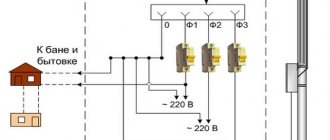
It is proposed to consider the connection diagram of a two-pole circuit breaker.
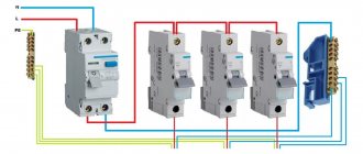
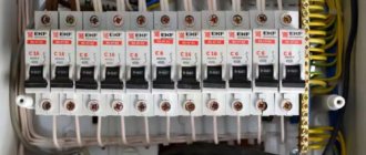
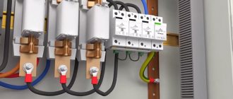
Here VA 47-63 2/50A is an introductory two-pole circuit breaker. It completely de-energizes the entire circuit if necessary. A meter and an RCD are connected behind it. Next, a connection diagram for a number of single-pole circuit breakers is used. They are installed only on phase wires, and neutral wires are distributed via a bus.
There is a connection diagram for a number of two-pole circuit breakers, each protecting its own branch.
The RCD is connected first at the input, then two rows of two-pole switches. The neutral wire is blue, the phase wire is red, and the grounding distributed using a grounding bus is yellow. In this way, each branch of the circuit is protected.
Installation
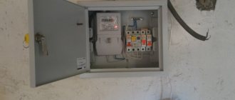
How to properly install circuit breakers in an electrical panel? First, DIN rails are screwed into it with self-tapping screws - these are metal plates, onto which all automatic devices and RCDs are then attached. The length of the DIN rail can be adjusted using a hacksaw. In addition, distribution terminal strips are attached to the shield. They can be for neutral wires and separately for ground wires. The modern configuration of the tires allows them to be mounted directly on a DIN rail.
Installing a two-pole circuit breaker on a DIN rail is very simple. Using a flat-head screwdriver, you need to pull out the snap-on bracket on the top of the case, attach the machine to the DIN rail and release the fastener. Removal is also carried out. According to the rules, the introductory machine is installed in the upper left corner.
Next you need to connect the wires. The scheme must be strictly adhered to. The phase and neutral input wires are connected to the two-pole circuit breaker from above, and the wires from below are discharged into the circuit. It is important not to confuse: the entrance is from above, the exit is from below, otherwise the machine may fail and will not perform its functions.
You can connect machines using jumpers made of copper wire of the same cross-section as the circuit wire. Jumpers are required to connect two-pole circuit breakers in a row. And also with the help of combs - these are insulated buses, used to connect single-pole circuit breakers.
The ends of the wires are stripped using a special stripper tool or a sharp knife. Then they crimp the cable lugs with a hand tool using a crimper. If there is no such equipment, then you can simply tin the ends with a soldering iron using rosin and tin. When connecting wires to machines, it is necessary to tighten the bolts firmly with a screwdriver so that weak contact does not cause heating and damage to conductive materials.
The grounding wire always passes past the machines directly to the grounding bus. The neutral wires are connected to the neutral bus.
Electrician tips
How to connect it correctly and are all such circuit breakers the same?
What are the features and nuances when installing two-pole circuit breakers and what does the “bible” of electricians, PUE, say about this?
First things first.
So, where are two-pole circuit breakers used?
Based on the name of the machine, it follows that they are used where the power supply to electrical equipment is supplied through two wires and simultaneous automatic switching of the two poles of the machine is required.
For example, a 220/36 Volt step-down transformer, where a two-pole circuit breaker is installed on the secondary winding to protect against overload.
If to protect the primary winding of such a trans you can use a single-pole circuit breaker: connect a phase to it, and connect the zero through the zero bus in the switchboard, then you cannot protect the secondary winding this way.
There is no phase and no zero, but there is a linear voltage between the two terminals of the secondary winding with a voltage of 36 Volts. Well, to put it simply, there are two different phases.
And in this case, a two-pole machine is used.
I want to clarify right away - there are two types of two-terminal networks - 2P and 1P+N. What is their difference?
The 1P+N circuit breaker, or as it is also called, “single-phase with zero,” differs in that the functions of automatic protective shutdown are available only in the “phase” pole.
The second pole simply serves as a load switch and is used to connect the neutral wire; it is also used in automation as a normally open contact, or you can simply connect a wire through it to a signal lamp and you can control the on position of the machine - the lamp will light up.
Of course, such a machine can be used as a simple single-pole one. In this case, we must connect the “phase” to its place (in no case to terminal N!).
For residential electrical wiring, such 1P+N circuit breakers are quite suitable and have advantages over single-pole ones.
For example, if an RCD installed in front of such machines is triggered, to find the fault it will be enough to turn off all the machines, then turn on the RCD and turn on the machines one by one until the faulty electrical wiring line is found.
And if there were simple single-pole ones, then we would have to open the shield, unscrew the wires from the neutral bus, etc...
The second type of two-pole circuit breakers is 2P.
They already have both poles protected from overloads and short circuits, and when connecting, it makes absolutely no difference where to connect the zero and where the “phase” is connected. These machines are wider than 1P+N.
It is not necessary to connect a 2P phase and a neutral to the machine; it is quite possible to connect two phases, both the same and opposite. In addition, the jumper between the power keys can in this case be removed and the load controlled separately.
You cannot remove the jumper if the phase with zero is connected through the machine!!!
This is a gross violation of the PUE and is very life-threatening! If the zero key is disconnected from a short circuit, a life-threatening potential (voltage) may appear on the body of the electrical device!
Such machines also don’t care which side the load is connected to - top or bottom, it doesn’t matter. This is also not prohibited by the rules, but I still recommend connecting the power from above and the load from below.
And if you do the opposite, then only in the most extreme cases.
I myself had such cases when I inserted old electrical wiring into an installed panel and its length was not enough to connect to the upper terminals of the machine.
And in order not to split hairs - extend the wire, install the junction box, I connected it to the lower terminals. But such cases were very rare and an exception to the rule.
And now about the main thing.
Such two-pole circuit breakers can be installed as input circuit breakers, as well as for group and individual loads. The PUE does not prohibit this.
PUE is the “bible” of an electrician, it stands for “Rules for the Construction of Electrical Installations”.
This is what the “bible” tells us:
clause 6.6.28. “ In three- or two-wire single-phase lines of networks with a grounded neutral, single-pole switches can be used, which must be installed in the phase wire circuit, or two-pole ones , and of disconnecting one neutral working conductor without disconnecting the phase conductor must be excluded
In our apartments, we mainly use two-wire (two cores in a wire - 220 Volts) single-phase electrical wiring with a grounded neutral.
Important note: if the electrical wiring is three-wire, that is, phase, neutral and ground, then the ground wire must not be in all cases !
Grounding (PE wire) is never connected through a circuit breaker, plugs, fuse, etc.! Disconnection is only allowed through the plug connector!
I think I’ve basically told you everything, if you have any questions, ask, I’ll answer!
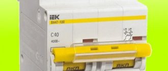
Marking
Particular attention should be paid to the markings of machines.
There are special markings on the body of the machines:
- Rated current of the device (in amperes).
- Overload current group (operation current range).
- Maximum operating current or short circuit current (in amperes).
- Current limiting class (the higher the class, the higher the response speed during a short circuit).
- Graphic designation or schematic diagram of the device.
- Device series.
- The rated voltage at which the machine must be used.