When connecting the meter yourself, you must have certain knowledge. There must be an exact wiring diagram for the electricity meter, operating instructions and data from the technical passport of the device. And you can safely begin installing an electric meter in your apartment, and then invite representatives of the electricity supplier to check it, seal it and put it into operation.
Classification of electricity metering devices
Modern electricity meters belong to the category of multifunctional devices, with the help of which a complete record of all actions related to electricity consumption is kept. Until recently, these were devices of simple design, operating on the basis of magnetic induction, carrying out metering at a single tariff. With the development of electronics and the advent of various microcircuits, electricity meters have changed dramatically, being divided into types and types in accordance with their parameters and technical characteristics.
All metering devices are classified as induction and electronic. In the first case, magnetic induction is used, causing the magnetic circuit to move under the influence of current flowing inside the device. Through mechanical connections, the received data is transferred to a mechanical display, consisting of individual wheels with numbers. These devices are still used in outdated houses, but due to the low accuracy class, each old meter is gradually being replaced with a new type of equipment.
Modern metering devices are electrical devices in which a special shunt serves as a current sensor. Recording and analysis of readings is carried out using a microcircuit, through which all data is displayed on the display. Such meters provide high accuracy of readings, can keep records at several tariffs and store the received information in memory.
For single-phase two-wire networks, the use of an appropriate single-phase electric meter is provided, which is installed in most residential buildings. In industry and the private sector, three-phase meters with a three- or four-wire connection are used. Connection methods may also be different. In apartments, a direct connection is most often used, when the electric meter is connected directly to the measured network.
If the voltage is too high, a transformer connection option is used. In this case, the electric meter works in conjunction with an instrument transformer.
Currently, multi-tariff metering of consumed electricity is becoming increasingly popular. In this case, the calculation is carried out separately by day of the week and time of day, since the price for electricity is set differently for all periods of time. Basically, the calculation for a two-tariff meter is carried out according to the “day-night” scheme, which is most convenient for consumers.
Three-phase meters with semi-indirect connection
Electric meters "Mercury" with a semi-indirect connection principle are connected to the 380V alternating current network through a transformer. Thanks to this, it becomes possible to meter electricity with high network power. At the same time, in the process of calculating the resources used, the transformation coefficient must be taken into account. Today, there are quite a lot of semi-indirect circuits, the most popular of which are the following options:
- transformer connection circuit according to the “star” principle;
- ten-wire connection;
- connection diagram using test terminal boxes;
- by combining current and voltage circuits.
Considering the disadvantages of a semi-indirect connection scheme, I would like to note the difficulty of carrying out scheduled inspections by energy sales regulatory authorities.
Requirements for connecting electricity meters
There are general requirements for the installation and connection of metering devices to the power supply, determined by the Rules for the Construction of Electrical Installations and regulatory documents of organizations that supply electricity. This is especially true when performing the task of how to connect a single-phase meter.
All electric meters are installed in panels, panels of input distribution devices, and other structures with a rigid base that is not subject to vibrations and other mechanical influences. This ensures safe and convenient installation, maintenance and replacement of devices. Wiring is easy to connect at both input and output, as long as the terminals are easily accessible.
As a rule, metering devices are provided with individual installation locations in the form of separate compartments, the doors of which are locked. The doors must have a special window through which the display board can be viewed. If current transformers are used in the circuit, it is best to mount them on top of the meters. A special partition is installed between these devices to act as insulation.
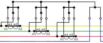
Semi-indirect connection diagram
It is quite difficult to make a compact device for high currents. That is why, for currents in the network of more than 100 Amperes, the connection of a three-phase meter is done through measuring transformers. This scheme works in circuits up to 0.4 kV.
With this scheme, current transformers are installed in the cable compartment on each phase wire. Metering lines are laid from the current transformers to the meter. The cross-section of the metering line wires is 1.5 (2.5 is possible) mm.
The meter is connected through a terminal block, which is located (usually) near the meter and is correctly called a transition test box KIP or KII 5/25.
With this connection scheme, the meter is installed remotely from the cable lines, which is good.
Connecting a single-phase meter
Before connecting the meter with your own hands, you need to prepare a place for its installation. Therefore, in the most convenient place, near the power cable entry, a shield or special box is installed to accommodate a single-phase metering device and protective circuit breakers. Such cabinets can be made of metal or plastic. They are installed from the floor at a height of 0.8 to 1.7 m, ensuring electrical safety, making maintenance and readings convenient.
Modern cabinets are pre-equipped with DIN rails. There are also busbars for grounding and grounding, which greatly facilitate installation work. This includes the installation of an input circuit breaker, the power of which is higher than that of protective devices that disconnect individual lines in the apartment. Thus, first, all devices and equipment are installed, all types of loads are connected, and only then voltage is supplied to the electrical circuit. After this, a working diagram for connecting a single-phase meter is obtained.
Three ways to install a three-phase electric meter
In household circuits, two methods of installing a three-phase electric meter are practiced:
- The first method is through instrument transformers (semi-indirect connection);
- The second method is direct installation, otherwise called direct-flow connection. It is possible in electrical circuits up to 100 Amperes.
- In industrial circuits of high-voltage lines, indirect connection of a three-phase meter through a current transformer and a voltage transformer is practiced; such a connection is called indirect.
Direct connection of a three-phase meter
The main difference between three-phase meters and single-phase metering devices is the technical ability to connect them to high-power electrical networks. If conventional 220-volt devices are capable of operating at a maximum power of 10 kW, then a three-phase device can withstand loads of 15 kW and above. They are widely used in industry, and more recently in country cottages and private homes, where the amount of powerful electrical equipment used is constantly growing.
The connection diagram of a three-phase electric meter largely depends on the type of device. Such devices, if necessary, can be connected to standard 220 volt networks. In everyday life, several schemes are used that are among the most reliable and effective.
The simplest option is considered to be direct connection, approximately the same as when connecting a single-phase meter. The main difference is the significantly larger number of terminals compared to similar single-phase equipment.
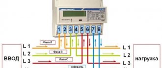
If we take the Mercury meter as an example, then its installation and connection are carried out in the following order:
- On the input conductors, the ends are stripped of insulation, after which they are connected to the input three-phase circuit breaker.
- After exiting the machine, the three phase conductors are connected to terminal contacts 1, 2, 3, located in pairs on the right side of the meter. To output these phase wires, the corresponding odd terminals 4, 5, 6 are used.
- Neutral conductors at the input and output are connected to the two outermost contacts 7, 8.
- At the output of the electric meter, the conductors are connected to the contacts of three-pole protective circuit breakers.
Preliminary stage
Connecting an electric meter (ES) is the final stage of electrical installation work.
Before installing a three-phase ES, you must first have a wiring diagram. The device must be checked for the presence of seals on the casing screws. These seals must indicate the year and quarter of the last inspection and the seal of the verifier. When connecting wires to the clamps, it is better to make a reserve of 70-80 mm. In the future, such a measure will allow measuring power/current consumption and rewiring if the circuit was assembled incorrectly.
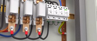
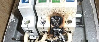
Each wire must be clamped in the terminal box with two screws (they are clearly visible in the photo below). The top screw is tightened first. Before tightening the lower one, you need to make sure that the upper wire is clamped by first tugging on it. If a stranded wire is used when connecting the meter, it must first be crimped with a tip.
Figure 1 – TS Mercury 231
Next, we will consider typical diagrams for connecting a three-phase meter to the electrical network.
Why are three-phase electricity meters popular?
Currently, in addition to traditional two-phase electricity meters, the popularity of three-phase meters has increased. This is due to the versatility of three-phase meters, as well as the ability to slightly reduce the cost of electricity consumption in the home.
In order not to be unfounded, we will tell you that when using a single-phase connection for a 20 kW consumer, a large cross-section cable would be required. In this case, load distribution is problematic, since one phase and zero will be involved. A three-phase connection solves such problems completely.
The need for a three-phase meter is due to the measurement of active and reactive electricity. It is necessary to distinguish between electronic active and reactive meters: • single-tariff active direct-connection meters with accuracy classes 1.0 and 2.0, equipped with an indicator • multi-tariff one- and bidirectional.
Connection to a single-phase circuit
To connect a meter designed for three-phase power to a single-phase network, you will first need to become familiar with the differences between these two types of power supplies. With each of them, the cable supplying voltage from the transformer substation contains a neutral working conductor N and phases (one or three).
In a single-phase network, the voltage difference between phase conductors A, B, C and zero is 220 Volts, and between the phases themselves is 380 Volts. The so-called “linear” voltage is formed due to the fact that the vectors of the acting potentials on each of the phases are shifted relative to each other by 120 degrees.
With the abundance of different models of single-phase current meters on the market, the inclusion of a three-phase meter in a single-phase network is used extremely rarely. In most cases, the circuit of such switching is similar to direct connection. The difference is that lines B and C are not connected to the meter; only one phase must be connected. A significant disadvantage of such inclusion is the possibility of problems with regulatory organizations, which really do not like all connection options that do not comply with current regulations and standards.
The significance of the meter, how to correctly take readings from the electricity meter
Control of consumed electricity is carried out using a special device - an electric meter, which is a device where a power meter and a counting mechanism are installed. To avoid any disagreements or problems with organizations supplying electrical energy, you should know what the meter value is and how to take readings correctly.
Electric meters: features
Electricity consumption metering devices are divided into:
- direct and alternating current;
- single-phase and three-phase.
The first such devices were three-digit, that is, the digital mechanism made a full revolution in a thousand kilowatts. This was quite enough for Ilyich’s light bulb, but in modern life this is not enough. The amount of energy consumed is increasing all the time, so the value of the meter is increasing. Nowadays, there are four-, five-, and seven-digit electricity meters.
Advantages and disadvantages
The device is capable of measuring power with potential difference, phase current, network frequency and phase power. Has maximum protection and event log. It takes into account electrical energy in any direction and transmits energy consumption data for each phase. Contains a power archive. Takes into account energy loss and magnetic influence. Controls the quality of electrical energy. Measures energy both per day and per year. Can be programmed for a new tariff.
As for the shortcomings, the main disadvantage is the low-quality case. According to user reviews, the load indicator often breaks down.
Specifications
Electronic meter "Mercury 230" is a device with increased accuracy and reliability. Operates approximately 150,000 hours. Works properly for 30 years. Warranty - 3 years. The current rating is 5 amps and the base current is 10 amps. The highest current value is 60 amperes. Phase voltage is 230 volts and frequency is 50 hertz. It has several modes of pulse outputs: main with verification. It differs in that it is not capable of creating more than 1 pulse per 10 minutes in the absence of current. The device is durable and reliable.
Note! This is explained by the high power of the electrical network due to the large accumulation of electrical appliances.
Principle of operation
The meter takes into account active and reactive electricity and power in three and four-phase AC networks using measuring transformers in daily zones, taking into account energy losses and transmitting this information through digital interface channels to the user.
It is important to understand that the Mercury meter comes in direct, indirect and semi-indirect connections. In the first case, the device is connected to the network; in the second and third cases, a transformer is used.
Step-by-step instructions for installing the meter
First of all, we prepare the kit for work. We will need the following:
- counter and shield;
- installation tools with pre-insulated handles;
- insulators;
- switches (automatic);
- wires;
- fasteners (screws and nuts);
- voltage meter;
- DIN rails.
Metering panelInstallation of a meter
Next we work in this order.
Second step
We install the metering device into the body of the protective shield. Fastening is carried out using special clamps from the kit.
Installation of the platform Prepare the installation wires We insert three phases into the meter, connect the lower terminals. Phase A enters terminal 1 of the meter, exits terminal 2 to the load; phase B enters terminal 3, exits into 4 and phase C enters 5, and exits from 6. 7 and 8 are zero
Third step
We install switches. We will attach them to the DIN rail with a special spring-loaded latch. We first fix the rail itself with screws to the support insulators.
Fourth step
We install grounding and protective busbars. We attach them to a DIN rail or insulators in the body of the protective shield. Fixation is carried out with screws and nuts. We place the buses at such a distance that the possibility of shorting the wires is excluded.
First, we connect the load to the switches, then we connect the machines to the meter, and only after that we connect the meter itself.
JumperConnecting OPS
Fifth step
We connect the loads. We connect the phase to the lower terminals of the switches, connect the zero to the zero bus, and connect the ground wire to the ground bus.
Sixth step
We install jumpers connecting the clamps on top of our machines. Jumpers are sold in specialized stores. We first buy the required number of jumpers according to the number of machines.
Zero bus Fasten the wire to the grounding bolt
Seventh step
We connect the electric meter to the load. To do this, we connect the “phase” output (which is the third terminal of the metering device) to the upper terminals of the machines. Next, we connect the “zero” output (represented by the fourth terminal of the metering device) to the zero bus.
Eighth step
We fix the body of the electric meter panel on a wall or other suitable flat base. Maintain a comfortable height.
Ninth step
We find phase, zero and grounding. If there is no grounding, we check each core with a special indicator. This simple device will help us find the phase. If there is a ground connection, you will easily recognize it - usually this wire is painted or marked green.
Thirteenth step
We contact the local energy sales office for additional checks and sealing of metering equipment.
Work completed
At this point, the work of manually installing and connecting the electric meter is completed.
Congratulations, you have successfully completed all the activities and saved money on the services of third-party installers!
Close the protective covers of the metering board and fasten them with self-tapping screws
Varieties of semi-indirect method
There are several known meter connection schemes based on the semi-indirect method, but the most common are the following:
- ten-wire circuit;
- connection by disconnecting on a special block;
- star connection.
Ten-wire switching
Connecting a 3-phase meter using a 10-wire circuit is the simplest and most reliable way. To implement it, you will need to follow the order of connecting ten wires: three for each phase and one neutral. This option has one indisputable advantage, which is the ability to replace the meter while the power is on. The line may be left energized even when repairing a device disconnected from it. With this scheme, the current circuits are reliably grounded, so the possibility of dangerous potential appearing on them is eliminated.
Another advantage of the 10-wire connection is the independent connection of each of the three phases. If one of them disappears, the remaining two retain the functionality of the device.
Other connection diagrams
Connection through contact distributors refers to more complex methods, implemented by switching each of the wires coming from the current transformer. The star connection is also characterized by its complexity, but in this case fewer conductors are used. When installing the converter, first the unipolar outputs of all three secondary windings are collected at one common point. After this, the three mating ends of the CT windings are connected to the corresponding terminals of the meter.
Another known switching scheme using the semi-indirect method is called 7-wire. When organizing it, one of the ends of the windings are combined by jumpers directly in the current transformer itself. This option is used extremely rarely in private homes, which is explained by a number of disadvantages of the switching scheme.