Home » Electrical installation » Electrical panels » Main distribution board
The main distribution board (MSB) is a distribution device that is responsible for receiving and further distributing energy throughout the building. Main switchboards can also be connected to networks with a solidly grounded neutral type of grounding:
- TN-C;
- TN-S;
- TN-CS.
Main switchboard
It can also be used to protect lines from overload, current leakage and short circuits. The device may contain emergency automation, as well as electricity metering devices. To purchase high-quality switchboard equipment, follow the link elektrika.ru. In this store you can expect low prices and high-quality equipment.
Design
The panel structure must necessarily include the following parts: introductory, sectional, linear panels. Input machines will be installed in the water panel, which are responsible for receiving electricity from transformers and other metering devices. In a sectional panel, specialists usually install an automatic switch, which allows powering several sections of one input. ATS can also be placed here. This device is used for backup power supply.
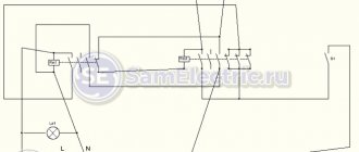
Automatic reserve input
The main switchboard circuit can be varied, as it depends on the number of incoming and outgoing lines. Most switchboards can have a circuit with two inputs and two outputs. When using such a scheme, the input will be from 2 transformers, and the output will go through the sectional panel to the distribution buses. Many electricians consider the main advantage of the main switchboard to be that all sections are collapsible.
The main characteristics that you need to pay attention to during purchase include:
- Nominal points of input and output lines.
- Rated mains voltage.
- Grounding system.
- Degree of protection according to GOST.
Each distribution board can be equipped with the following metering devices:
- automatic switches;
- control and measuring instruments;
- metering devices;
- load switches;
- automatic entry of reserve.
If you install the correct devices in the main switchboard, then you can use it to replace the ASU. The main difference between the main switchboard and the ASU is the strength of the maximum input current.
Automatic switches in main switchboards
Main switchboard decoding, device, purpose. What is the difference between an ASU and a main switchboard?
Main distribution boards are designed for full or partial redundant power supply, three-phase alternating current with a rated operating voltage of 380 V and a frequency of 50 Hz in public and industrial buildings.
Contents
hide
1 What is the difference between an ASU and a main switchboard?
2 Typical power supply system with main switchboard on the upper level
3 Schematic diagram of a typical main switchboard main switchboard
What is the difference between an ASU and a main switchboard?
There are many devices in the electrical distribution system. Each of them has its own characteristics and purpose. But certain categories are so closely intertwined that it is difficult to tell the difference. First of all, this concerns electrical switchboard equipment. Here two concepts are often confused - ASU and main switchboard . Even experts cannot always immediately identify the differences, although they probably feel the difference on an intuitive level.
Indeed, the main distribution board ( MSB ) and the input distribution device ( IDU ) are very similar in their design features and functional purpose. Both are designed to receive and distribute electricity. Both are equipped with protection and current characteristics monitoring devices. But still, there are two abbreviations, which means that there is a difference between these concepts. Let's figure out how the ASU from the main switchboard ?
Electrical switchboard equipment has its own hierarchy. And the first input device, of course, is considered the main one. It controls the distribution of electricity between all subsequent panel devices in this hierarchy. So the difference in theoretical concepts is that the main switchboard is at the very top stage, and all subsequent links in this electrical panel circuit are ASU . In practice it looks like this. Immediately after the transformer or boiler room there is a main switchboard . And at the entrances to buildings and on floors, ASUs . But within a specific scheme it may be different: at the entrance to the building there is a main switchboard (main distribution board), and on the floors there is an ASU . That is, these concepts determine only the position of a link in the chain, the level in the hierarchy at which this or that switchboard equipment is located.
The practical side of this issue can be explained even more simply. During manufacture, electrical panel equipment is marked. Along with the serial number and other information, it will almost certainly say “ VRU ”. But when installed at the site as the main electrical panel, this equipment will be marked “ main switchboard ”. And in the project documentation it will appear the same way. That is, it turns out that the ASU is the designation of the product, and the main switchboard is the functional purpose that this product performs.
In fact, the information provided makes it possible to answer the popular question: “what is at the entrance to the building - an ASU or a main switchboard? ". If after the first ASU , which is located at the entrance to the building, there are more ASUs , then a hierarchy arises. Then the first ASU will become the main one and will appear on the diagrams as the main switchboard . If the ASU is the only one, then it is permissible to use both the abbreviation ASU and main switchboard . That is, formally this ASU will be the main one, but at the same time the only one. So in this case, you can emphasize its functional purpose by designating it on the diagram as main switchboard , or simply use the name of the product - ASU .
But these are not all the differences between the ASU and the main switchboard . There is also a formal difference in the permissible current characteristics. It is worth noting here that both concepts are in the PUE (clauses 7.1.3 and 7.1.4) . In addition, these concepts are used in the set of rules (SP 31-110), where there are references to GOSTs. So, if we summarize the information from all this documentation, it will become clear that there are current limitations for the ASU. Thus, the maximum input current should not exceed 630A, and the maximum load on each supply line extending from the ASU should not exceed 250A. At the same time, for switchboard (main distribution board) there are no restrictions on input and output currents. By the way, this confirms the information that the main switchboard is not the name of the product, but only a designation of the ASU as part of the electrical network circuit.
Thus, the concepts of ASU and main switchboard refer to the same type of devices and with the same purpose. But at the same time, these are not synonymous words. The use of one or the other of them will depend on what you want to emphasize - the purpose of the device (that is, the main switchboard as the main ASU ) or its relationship to a certain type of device (a product called ASU ). This is the fundamental difference.
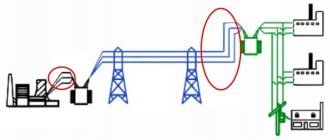
Typical power supply system with main switchboard at the top level
Main distribution board (MSB) - Main switchboard , through which electricity is received and distributed throughout the building or some part of it. As we noted above, an input distribution device or a low voltage switchboard of a substation can serve as a main switchboard. The main switchboard contains emergency automation (for example, circuit breakers or RCD devices), and electricity metering devices (meters).
Main distribution boards the MSB type are manufactured in a multi-cabinet floor-mounted design, designed for the distribution of electrical energy, protection of electrical installations with voltages up to 660 V AC with a frequency of 50, 60 Hz.
The main distribution boards of main switchboards are most often located in the power supply system of a building (structure) at the upper level of power distribution with a voltage of 0.4 kV.
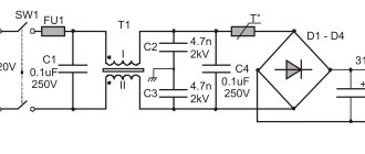
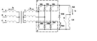
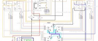
Schematic diagram of a typical main distribution board
Schematic diagram of a typical main distribution board.
Share link:
You might be interested in:
- Surge suppressor - its types and capabilities
- Selectivity of circuit breakers, connection to...
- PUE RULES FOR ELECTRICAL INSTALLATIONS
- What is an ASU - decoding and packaging
Marking of electrical panels
The wires of all internal circuits must be color coded. It must have a sharp contrast and be resistant to abrasion. Terminals for PE and N conductors that extend from distribution and group circuits should be marked with serial numbers. If connecting wires to the device terminals is difficult, then intermediate clamps must be provided. The clamps must also be marked with serial numbers.
A sign with information must be placed on the door on the outside of the main switchboard. Typically the nameplate contains the following information:
- Manufacturer's name.
- Type designation.
- Device protection level.
- Rated current of the ASU.
- Weight.
- Identification of all technical conditions.
- Date of manufacture.
- Additional Information.
Marking in the main switchboard
Installation technology
Power supply to the main switchboard today is carried out through the main busbar and is produced from the low side of the transformer. The electrician should also remember that the main switchboard sections should be powered by mutually redundant lines.
Before starting installation, you must first place the circuit breakers on the mounting panel. Then it is necessary to adjust the placement of the copper busbars in the busbar holders of the device. The easiest way to install equipment is when the main switchboard is located on the table. All automatic input elements must be placed on a DIN rail. When locating high-power circuit breakers, they should be located one below the other. Thanks to this arrangement, the amount of work required to disconnect the tires will be significantly reduced.
Main switchboard wiring diagram
PE and N busbars are usually installed on insulators and subsequently fastened together along the entire length. In the future, holes are made in them to disconnect the cable lines. To exclude the possibility of further electric shock, plastrons are installed, which are made of non-flammable material. If you are interested, read about the distribution panel assembly diagram.
Safety requirement when installing main switchboards
General labor protection requirements
- Only persons over 18 years of age are allowed to work in the distribution panel. Also, before working in the main switchboard, they must undergo a medical examination, induction training, initial training, as well as training and internship. The electrical safety level must be at least group 3.
- The work of a specialist must be defined by a work or job description.
- It is necessary to comply with internal labor regulations.
- Individual or collective protective equipment should be used correctly.
- If a situation arises that threatens people's lives, you must inform your superior. A specialist who works with the shield must undergo regular medical examination.
- During work in the cabinet, hazardous or harmful production factors may occur.
- The employee must be provided with special clothing, shoes and other personal protective equipment.
- As a result of injury, work must be stopped immediately and the supervisor must be informed.
Requirements before starting work
- You should select the necessary tool to begin the work. Tools must be visually inspected to ensure they are in good working order.
- Wear special clothing.
- Before carrying out work, inspect your workplace.
Requirements in emergency situations
- If faulty equipment occurs, the employee must notify his superiors.
- If the smell of gas is detected, work must be stopped immediately.
- Gas removal work should be carried out by professionals.
- If you are injured, you should stop working and contact a medical facility.
- If an accident occurs, then the victim needs to provide first aid.
Requirements while working
- Before starting work, the worker must make sure that there is no extraneous voltage.
- Warning signs must be placed on the outside of the internal door of the ShR type cabinet.
- The inlet hole, which is located in the cabinet, must be hermetically sealed.
- Before using a blowtorch, make sure there is no gas in the cabinet well.
- Smoking in the control cabinet during work is prohibited.
Requirements upon completion of work
- The workplace should be put in order.
- Close the closet.
- Gather all the tools.
- Inform management about any shortcomings you find in the shield.
Signs on the main switchboard
Characteristics of electrical panel locations
The electrical panel for an apartment is usually a box made of plastic or metal. DIN rails are located inside it. This is a special metal profile used for electrical work. Modular circuit breakers, differential relays, sockets, and so on can be easily installed on a profile of this type.
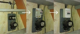
Previously, meters were also installed in apartment panels. But according to the new requirements, electricity meters are moved outside of residential premises (houses and apartments). They are placed on staircases in floor panels or in hanging boxes on the walls of houses. This is necessary so that the inspector can at any time, without going inside the house or apartment, gain access to the meter and take readings from it.
The influence of the location of the electrical panel in the apartment.
The location of the electrical panel in the apartment must be chosen with special care. The following indicators depend on this:
- the total footage of electrical wiring from the panel to sockets, switches and lamps;
- convenient location, taking into account the need to find and use the shield in the dark (this is necessary, for example, to check and turn on a triggered machine);
- compliance with fire safety (shields cannot be installed close to hangers with clothes, in dressing rooms, and where there is a possibility of something igniting).
Existing restrictions.
There are restrictions on installation indicating places where electrical panels are strictly prohibited from being placed. These are the following places:
- rooms with high humidity: kitchens or bathrooms;
- walls near gas pipes, stoves, and/or water heaters;
- places located above the access level of an adult (this requirement is necessary to be able to see the markings and operate machines and automatic machines).
The best places to install residential electrical panels.
- The best places are those with free access. These are corridors, hallways, or those that will not be filled with trash under any circumstances. Because this can make access difficult and increase the risk of fire.
- The brightest places (if possible).
- Places where there is good, preferably natural, ventilation. This requirement must be met so that if there is a short circuit and a certain amount of smoke is released, it can dissipate.
- Don't forget about the housing for the shield. A panel for automatic machines in an apartment should look good and fit into the overall design of the apartment. A convenient and rational solution is a niche near the front door, which many modern apartments are equipped with. For a niche, you just need to choose a suitable door.