The owner of the house has to master a huge amount of information that has nothing to do with his professional activities. It’s just different communication with representatives of various organizations that supply us. Very few people can explain in simple terms what happened or what they need. So you have to be aware of most of the terms they use. For example, when connecting to the mains or when there is no light, we often talk about “electric feeder”. Moreover, electricians themselves cannot always explain what it is.
What is a feeder in electrical engineering?
The name of the term comes from the English word “feeder”, which has several translation options. Of these, the closest to the energy area is the “auxiliary line,” which perfectly describes the purpose of the electrical feeder. This is perhaps the only clear definition of this term in the energy sector, since it does not appear in regulatory documents.
This situation causes some confusion even among professionals, since this term can mean both power lines from which the main substation units are powered (see Fig. 1), and lines between transformers and certain switches. Also, in some cases, cable networks and overhead lines with a voltage class of 6.0-10.0 kV fall under this concept.
Feeders in the figure are marked in red
Please note that taking into account the translation of the word “feeder”, such an expression as “feeder lines” will be perceived as a tautology, so it is better to refrain from using it.
How to understand electricians' messages
Few of the power grid workers speak “human language.” Their messages must be translated from a special dialect to a “general” one. And not each of them can clearly tell what exactly he told you, without using complex or incomprehensible words. We will try to explain a few common expressions.
There can be many different devices in a feeder distribution network. These are high-voltage switches (the correct name is “switching devices”), arresters, current and voltage measuring transformers, insulators, buses. Cable or overhead lines are connected to the buses. And all this can be called the word “feeder” for the general definition of the damaged area. Then, as the damage is determined, the area is specified. But first they say “the fourth feeder has switched off” or “the fourth feeder is damaged.” When the cause of the shutdown has been found out, and it is a cable or one device on the transformer substation, they can clarify that the damage is “in the feeder network” or “feeder network” and further clarify what exactly is faulty - the feeder cable, the feeder circuit breaker or switch, another device. But ordinary “mortals” are not given such information.
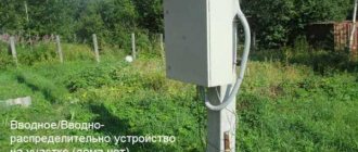
Such transformer substations are common. Usually they are designated TP-1, TP-2, etc. on the diagrams. If we consider them, the electrical feeder is partially located inside (different devices), part is an overhead line to the next switchboard
When they say “Electrical feeder has gone out,” it usually means that a certain area is without power. In some schemes, it is possible to switch the load (consumers) to other feeders (sections) so that consumers are not left without power supply while the damage is repaired. But such schemes are usually developed for enterprises, organizations and other significant objects. Private houses are not included in this list.
If you are a home owner and you have been told that your feeder is damaged, most likely you have been told that there is a problem with the cable that runs from the panel on the pole to the input switch. That is, you need to change the cable or look at the connection points. Maybe the terminals have oxidized, maybe the contact on the switch.
Types and classification
Considering that this term has several definitions, it is reasonable to classify it according to the area of application, we list them:
- Radio engineering (radio feeder) . In this field, a feeder refers to the lines that carry the RF signal from the antenna device to the receiver, and also provide communication between the transmitter and the antenna. In this area you can also find the following terms:
- high frequency feeder (coaxial cable);
- feeder cable (same meaning as above);
- feeder bridge (a structure for the cable line from the antenna complex to the technical room).
- Electronics manufacturing . Sometimes the power input on CNC machines is called a feeder input. In this case, there is an incorrect translation of the technical documentation for the equipment, but this term has taken root and is often used.
- Among the fishing equipment there is feeder equipment.
- Paintball equipment . This term applies to the mechanism for feeding the balls into the marker, as well as the container in which they are placed.
- Energy . Not everything is so certain here, so
- As already described above, in the energy sector there is no clear definition of the term feeder, so classification is possible only on the basis of practical application.
How to identify a feeder line
The only official source in which the meaning is clearly defined is the still valid GOST 24375 - 80 “INTERSTATE RADIO COMMUNICATION STANDARD Terms and Definitions”. Based on this regulatory document, it turns out that this is an electrical circuit and its auxiliary devices, designed to supply radio frequency signal energy from the transmitter to the antenna and from the antenna to the receiver.
In this case, auxiliary devices include valves, connectors, phase shifters and other equipment. It is considered incorrect to use the definition of “feeder line”, therefore it is only permissible to use “feeder” to a set of equipment and technical means on a designated section of the circuit. Please note that based on the legal definition, our subtitle is considered incorrect, it is provided solely for understanding the information. Therefore, we will not use such a concept in the future.
By analogy with this legalized definition for radio communications, the definition in electrical engineering and energy has a similar meaning. Depending on the situation, it is considered to be any section of the network between the source and the consumer or intermediate equipment.
Feeder at substation
Let us give a practical example that will help you understand how this term is viewed in the electric power industry. For this purpose, consider a fragment of the substation diagram given below.
Substation diagram fragment
In this example, the definition of feeder includes the entire circuit with switchgears connected to the substation cell F101, that is, sections designated on the diagram as A and B. At the same time, this term can be used to describe the line supplying power to the network of switchgears (A ). In this case, section B will be considered as feeder network 101.
If it is necessary to remove the load from a specific feeder, then the circuit breaker of a specific feeder cell is turned off. When we talk about feeder damage, this means an accident on the power line of the distribution network (section B).
On the one hand, this allows you to accurately identify a section or line, on the other hand, it introduces confusion. For example, disconnecting the feeder can be understood as disconnecting the cable from the cell and the main network switch (B), in the latter case the power supply line will remain energized. The currently practiced identification of lines by numbers eliminates such an error. As for the term “feeder”, it is used less and less.
Trunk and distribution lines
If you use high voltage when transmitting electricity, this makes it possible to avoid large losses on high-voltage power lines and you can install cables of a smaller cross-section. This especially plays a big role when transmitting electricity over long distances, since in this case the current strength decreases, which affects losses.
Standard trunk lines transmit electricity with voltages starting from 110 kV. Distribution networks use a voltage of 10 kV , which is obtained at transformer substations where the main feeder, its cells and protective equipment are located.
The outlet line connects the secondary winding of the step-down transformer to the distribution equipment, from where the supply feeder lines originate. Usually, when further transmitting electricity to consumers, the term “feeder” is not used.
Feeder design
We specifically used such a table of contents for the section to show its absurdity. This decision arose after browsing thematic forums and paying attention to frequently encountered questions regarding the design and appearance of the feeder.
The fact is that in energy, and electrical engineering in particular, the term is used as a definition that allows one to identify a particular section of a circuit by its relationship to the power source. That is, in this case, asking to describe the design of the feeder, or to show what it looks like, is equivalent to asking to provide a photograph of the power consumption.
Natural power and transmission capacity of power lines
Natural power
Power lines have inductance and capacitance. Capacitive power is proportional to the square of the voltage and does not depend on the power transmitted along the line. The inductive power of the line is proportional to the square of the current, and therefore the power of the line. At a certain load, the inductive and capacitive power of the line become equal, and they compensate each other. The line becomes “ideal”, consuming as much reactive power as it produces. This power is called natural power. It is determined only by linear inductance and capacitance and does not depend on the length of the line. Based on the amount of natural power, one can roughly judge the capacity of the power transmission line. When transmitting such power on the line, there are minimal power losses, its operating mode is optimal. When the phases are split, due to a decrease in inductive reactance and an increase in the capacitive conductivity of the line, the natural power increases. As the distance between the wires increases, the natural power decreases, and vice versa, to increase the natural power it is necessary to reduce the distance between the wires. Cable lines with high capacitive conductivity and low inductance have the highest natural power.
Bandwidth
Power transmission capacity refers to the highest active power of three phases of power transmission, which can be transmitted in a long-term steady state, taking into account operational and technical limitations. The maximum transmitted active power of power transmission is limited by the conditions of static stability of generators of power stations, the transmitting and receiving parts of the electric power system, and the permissible power for heating line wires with permissible current. From the practice of operating electric power systems, it follows that the transmission capacity of power lines of 500 kV and above is usually determined by the factor of static stability; for power lines of 220-330 kV, restrictions can occur both in terms of stability and in terms of permissible heating, 110 kV and below - only in terms of heating.
Characteristics of the capacity of overhead power lines
| Unom, kV | Line length, km | Limit length at efficiency = 0.9 | Number and cross-sectional area of wires, mm2 | Natural power P nat MW | Bandwidth | |||
| In terms of stability | By heating | |||||||
| MW | in shares of Rnat | MW | in shares of Rnat | |||||
| 10(6) | 5 | 1 | 2,1 | |||||
| 20 | 8 | 1 | 7,5 | |||||
| 35 | 20 | 1 | 15 | |||||
| 110 | 80 | 1 | 30 | 50 | 1,67 | |||
| 220 | 150-250 | 400 | 1x300 | 120-135 | 350 | 2,9 | 280 | 2,3 |
| 330 | 200-300 | 700 | 2x300 | 350-360 | 800 | 2,3 | 760 | 2,2 |
| 500 | 300-400 | 1200 | 3x300 | 900 | 1350 | 1,5 | 1740 | 1,9 |
| 750 | 400-500 | 2200 | 5x300 | 2100 | 2500 | 1,2 | 4600 | 2,1 |
| 1150 | 400-500 | 3000 | 8x300 | 5300 | 4500 | 0,85 | 11000 | 2,1 |
Application of feeders in electric power industry
The most obvious example will be traction substations that ensure the functioning of electric vehicles. Below is a simplified diagram of the organization of traction power supply.
Traction substation elements
Designations:
- A – Electric rolling stock.
- B – Rail contact network.
- C - High-voltage contact electrical network.
- D – Auxiliary line of traction power supply network.
- E – Return current feeder.
- F – Traction substation building.
To prevent overloading of the lines supplying the contact network, feeder automation is installed, which includes protective devices. In addition to the main one, the power supply circuit also provides backup protection to disconnect the line in the event of a short circuit. Most of the feeder equipment is installed at traction substations. Let us give as an example a typical block diagram of one of them.
Typical block diagram of a traction substation
Designations:
- RU-110 – distribution devices providing power supply to transformers.
- GPT1, GPT2 – Main step-down transformers.
- TSN1, TSN2 are auxiliary transformers; they are necessary to supply power to the substation equipment.
- PA1, PA2 – converting units.
- RU-3.3 is a switchgear that provides power to overhead contact line feeders.
Conclusion.
Taking into account the above information, it can be stated that this definition includes overhead and cable power lines that supply electric current to substations and main distribution nodes.
The feeder structuring system is quite convenient for identifying a specific section of the circuit (a specific feeder). But since there is no definition for this term in regulatory documents, there is a possibility of misunderstanding, which could cause an accident or accident. Therefore, it is better to adhere to the terminology adopted in regulatory documents.
It is important to study:
- Sample single-line power supply diagram
- Checking portable grounding
Device Description
When designing and constructing an electrical main, feeders include cables that connect distribution equipment to consumers or other nodes. Lines that continue from a distribution facility are called branches.
Electrical lines can be either open or laid in trenches. In both cases, they perform the same task, namely, connect busbars in switchgear to consumer electrical objects.
For example, in traction power supply, the section of the network connecting the voltage buses with the contact network also refers to feeders. For their safe operation, the equipment is protected by circuit breakers and high-voltage disconnectors.
All structural elements that belong to these areas are called feeder equipment. Thus, a feeder is practically a power transmission line or a separate section of it that supplies electricity to substations or other distribution nodes.
What does a feeder cable consist of?
To ensure that signal transmission using the feeder is as accurate as possible, a semi-rigid radio frequency cable with large dimensions is used. If the antenna is located far from the signal source, then in order to provide a cable of the required length, a connection using welded conductors is used. They can be either on the outside or on the inside of the cable.
A feeder cable is a device on which the quality of communication between the transmitter and the antenna depends. Since this type of cable is mainly used to provide a cellular signal, it is important that it is strong enough, of high quality, and correctly routed from the main installation that produces the radio signal to the antenna that broadcasts this signal over long distances.
The feeder can be found in any equipment that emits or receives a radio signal. It also exists in personal computers. If you need to choose a feeder cable with good signal transmission properties, you should start first of all from the purposes for which it will be used later.
During the selection process, pay attention to factors such as:
- indicator of wave resistance of the tract;
- feeder attenuation at the operating frequency of the signal source;
- average cable power at transmitter frequency;
- connecting channel at the transmitter output and antenna input;
- VSWR of the path;
- the conditions under which the cable will be used to transmit a signal - ambient temperature, exposure of the cable to sunlight, liquids during a thunderstorm, rain, general humidity of the environment through which it is pulled. These parameters determine how accurately the radio frequency signal will be transmitted, as well as what materials the feeder will have to be purchased from. The winding of a cable used in harsh climatic and other conditions must successfully withstand the influence of the environment;
- installation conditions - permissible limits of stretching, bending, materials used in the process of fastening it and the type of installation that was used. Even the air temperature at that moment can affect the accuracy of installation;
- the cost of the cable, its fastenings and installation.
What kind of lighting do you prefer?
Built-in Chandelier
It is also known about the feeder that it can be used as part of an antenna-feeder device. Moreover, its design can provide for either a separate type of fastening or execution as a single, inseparable device for various reasons. This is usually necessary to reduce the cost of the device or reduce its size.
What is a feeder in electrical engineering? Electrics from A to Z
To determine the load on the circuit, the individual power for all connected consumers is summed up. When calculating the load in each branch circuit, motor-driven devices, which consume more current at startup, are taken into account.
Expert opinion
It-Technology, Electrical power and electronics specialist
Ask questions to the “Specialist for modernization of energy generation systems”
What is a feeder in electrical and energy engineering - explanation A feeder for an electrician does not always represent any internal branching, since a branched circuit includes conductors between the final overcurrent device that protects the circuit and the socket, regardless of what current the fittings are designed for. Ask, I'm in touch!
The importance of accurate and correct feeder casting
- indicator of wave resistance of the tract;
- feeder attenuation at the operating frequency of the signal source;
- average cable power at transmitter frequency;
- connecting channel at the transmitter output and antenna input;
- VSWR of the path;
- the conditions under which the cable will be used to transmit a signal - ambient temperature, exposure of the cable to sunlight, liquids during a thunderstorm, rain, general humidity of the environment through which it is pulled. These parameters determine how accurately the radio frequency signal will be transmitted, as well as what materials the feeder will have to be purchased from. The winding of a cable used in harsh climatic and other conditions must successfully withstand the influence of the environment;
- installation conditions - permissible limits of stretching, bending, materials used in the process of fastening it and the type of installation that was used. Even the air temperature at that moment can affect the accuracy of installation;
- the cost of the cable, its fastenings and installation.
What the research showed
As a result, a standard for reporting electricity losses was obtained. Both electrical power and percentage display were used to evaluate it. Data on losses in all feeders were summarized and formed the basis for constructing the graphs presented below. These graphs show:
- the predominance of idling power losses of transformers over load losses;
- reduction in the share of technical losses with an increase in the throughput characteristics of the feeder against the background of a slight change in no-load losses of transformers;
- The loss standard increases if at no-load in transformers, due to their design features, there are significant no-load losses, leading to an increase in total technical losses.
Further on the graphs, the network load is shown on the abscissa axis, and the main losses are shown on the ordinate axis.
Table 1
Dynamics of changes in the components of technical energy losses
Dynamics of changes in loss components in transformers
Dynamics of changes in energy loss standards
Studying the flow of electricity through feeders allows us to construct the graphs shown above and draw the following conclusions:
- With an increase in the flow of electricity through the feeder (its head section), load losses increase, as does the total network load. At the same time, the standard for electricity losses mostly consists of the total technical losses.
- Changes in the standard mainly depend on losses in wires and cables, and not on load losses in transformers.