Radio electronics, or how I began to comprehend it
Good afternoon, dear community. I was always surprised by people who understand radio electronics. I have always considered them to be a kind of shamans: how can one make sense of this abundance of elements, paths and documentation? As soon as you can look at the board, “poke” the oscilloscope a couple of times in places that only one understands, and with the words “ah, I see,” take the soldering iron in your hands and resurrect, as if it were a deceased favorite toy. You can’t call it anything other than magic.
The heyday of radio electronics in our country occurred in the 80s, when there was nothing and everything had to be done with your own hands. Many years have passed since then. Now I have the impression that along with the generation of the 70s, knowledge and skill are also leaving. I was unlucky: my parents planned half of my heyday, and I spent the second half playing with blocks and other machines. When I joined the “Young Technician” club at the age of 12, those were not the most prosperous times, and due to circumstances, I had to give up the club after six months, but the dream remained.
By current activity I am a programmer. I realize that finding an error in a large code is exactly the same as finding a “bad” capacitor on a board. No sooner said than done. Since by nature I like to study on my own, I went looking for literature. There were several attempts to start, but every time I started reading books, I ran into the fact that I could not understand basic things, for example, “what is voltage and current.” Queries to the great and terrible Google also yielded template answers copied from textbooks. I tried to find a place in Moscow where I could learn this skill, but my search was unsuccessful.
So, welcome to the circle of beginner radio amateurs. I love to study and learn something new, but just knowledge is not enough for me. At school I was taught the skill “a theorem cannot be learned, it can only be understood” and now I carry this rule throughout my life. Those around me, of course, look with bewilderment when, instead of taking ready-made solutions and quickly putting them together, I start reinventing my own wheels. The second reason for writing an article is the thought “if you understand a subject, you can easily explain it to someone else.” Well, I’ll try to understand it myself and explain it to others.
My first goal, just like in the books, is an analog radio receiver, and then we’ll go digital.
I want to warn you right away - the article was written by an amateur in radio electronics and physics and is more of an argument. I will be glad to hear any amendments in the comments.
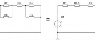
So, what is voltage, current and other resistance? In most cases, to understand electrical processes, an analogy with water is given. We will not deviate from this rule, albeit with minor deviations. Let's imagine a pipe. To control some indicators, we will include several water flow meters, pressure gauges for measuring pressure, and elements that interfere with the flow of water.
In electrical equivalent, the circuit would look something like this:
Voltage
The physics course tells us that voltage is the potential difference between two points.
If we transfer the definition to our water pipe, then potential is pressure, i.e. voltage is the pressure difference between two points. This explains the principle of measuring it with a voltmeter. It turns out that if you try to measure the voltage at two adjacent points of the pipe, where there is no resistance to the movement of water (there are no taps or restrictions, we will neglect the internal friction of water on the walls of the pipe for now) and the pressure does not change, then the pressure difference at these two points will be zero . If resistance is present, a decrease in pressure occurs (in electrical equivalent, a voltage drop), then we get the voltage value. The sum of the voltages on all elements is equal to the voltage at the source. Those. if we add up the readings of all the voltmeters in our diagram, we get the battery voltage. For example, let's assume that our battery produces a voltage of 5 volts and the resistors have a resistance of 100 and 150 ohms. Then, according to Ohm’s law U=IR, or I=U/R, we find that a current flows through the circuit with a force of I=5/250=20mA. Since the current strength in the entire circuit is the same (explanations a little further), it follows from the same Ohm’s law that the first voltmeter will show U=0.02*100=2V, and the second U=0.02*150=3V.
Current strength
From the same physics course we know that this is the amount of charge per unit of time. In water equivalent, this is water itself, and its meter, an ammeter, is a water meter. Again, it becomes clear why the ammeter is connected to the open circuit. If you connect it in place of, for example, voltmeter V1, then a new circuit is formed, from which resistance R1 will be excluded, which means at a minimum we will get incorrect values (which will be “at the maximum” will become clear a little later). Let's return to our water - connecting an ammeter in parallel to any of the elements means that part of the water will go through the main pipe, and the other part will go through the meter - and it is this meter that will lie.
Oh yes, about the chain. In most of the literature that I came across the phrase that batteries are only a source of voltage, and only resistances are a source of current. How so? How can resistance be a source of anything other than a source of resistance (heat doesn't count for now)? Everything is correct, if you rely on Ohm’s law I=U/R, but no matter how much resistance you apply, the current will not appear until there is a voltage source and a closed circuit (exactly like if you plug our pipe on the right with a stopper, whatever you do, the water meters will be silent) !
Resistance in the circuit simply must be present, because if it is zero, the current strength will rush to infinity. We see this situation during a “short circuit” - the spark is a very high current, or more precisely heat, equal to Q=(I^2)Rt (the formula is valid at a constant current and resistance).
Another important note - when considering the calculation of voltage and current, I did not find any clarification that in a closed circuit the current strength will be the same in all sections. Those. all counters will spin at the same speed and show the same values. Essentially, the amount of current that passed through the circuit is similar to the amount of “water” that came out of the pipe.
Resistance
Perhaps the simplest phenomenon to explain.
Returning to our pipe, resistance is all possible restrictions and taps. According to what we discussed above, as the resistance increases, the current in the entire circuit decreases and the voltage at the ends of the resistance decreases. Or again in water realities - closing our tap half a turn will cause a decrease in water flow on all meters and a proportional (depending on resistance) decrease in pressure on pressure gauges. So where does everything fall and decrease?
This is where the analogy with water is ambiguous, since in the case of electricity, the “excess” turns into heat and is dissipated. The amount of heat that is released in this case can again be calculated by the formula Q=(ΔI^2)Rt (again at constant resistance). If we divide the amount of heat by time, we get the power that needs to be applied when choosing the resistor itself P=Q/t=(ΔI^2)R. Smoking is not cool!
When I went to the Young Technician club, older comrades conducted “experiments” with lighting cigarettes using electricity. To do this, they took a power supply, connected low-power resistors to it and increased the voltage. They turned it up until it was as red-hot as a car cigarette lighter. After that, almost a moment later, the resistor “burned out” and went into the trash bin.
With direct current everything is clear, but alternating current?
Alternating current, as such, is rarely used in radio electronics.
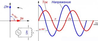
At a minimum, it is made constant and in most cases reduced. Apparently this is why the literature I came across practically does not talk about him. What is its difference? From a layman's point of view, in a small state, the direction of the current in it changes. Here the analogy with a pipe is not entirely appropriate; the first thing that comes to mind is a cocktail shaker (the liquid moves back and forth when mixed in it). In radio electronics, we need to know how the current flows in our circuit in order to get what we want from it.
The next thing I went to look into was semiconductors. Holes? Electrons? Key mode? Cascades? Field effect transistor, the one that was found in the field? Nothing is clear yet...
Components
Electrical Engineering for Beginners
In order to have a comfortable radio amateur workshop, it is enough to choose a well-lit corner of the room for the table. Several electrical outlets should be placed on the wall near the adjacent side of the table. In addition, you will need the following:
- electronic devices;
- basic measuring instruments;
- tools and materials.
Electronic devices
Adjustable power supply
First of all, you need to get a regulated power supply. The unit is connected to a household electrical outlet. Alternating current is converted to direct current with a voltage of 3 to 12 volts. The device consists of a transformer, rectifier and stabilizer.
Adjustable power supply
Transformer
Its secondary winding reduces the voltage of the current supplied to the primary coil from the electrical network from 220 to 12 volts. Both windings of the transformer are reliably isolated from each other. Therefore, high voltage entering the secondary winding in the event of a breakdown of the first coil is absolutely excluded.
Rectifier
The reduced alternating voltage is supplied to the diode bridge of the rectifier. Alternating current loses its return ability and is converted into a constant electric flow. To eliminate voltage ripple at the output, current flows through an electrolytic capacitor.
Stabilizer
The basis of the stabilizer is the MC34063 microcircuit. The radio component is equipped with a unit that protects against overload and short circuit in the circuit.
Multifunctional socket
A multifunctional power supply allows you to create the most comfortable working conditions for a radio amateur. During the assembly and installation of radio circuits, it is often necessary to connect several consumers simultaneously, both mains and 12-volt DC.
Multifunctional socket
The housing of the multifunctional equipment has a built-in general switch for all connectors. The device is also equipped with an AC converter unit.
Additional Information. A multifunctional socket can be purchased ready-made. It will be interesting for a novice radio amateur to assemble such a device with his own hands.
Basic measuring instruments
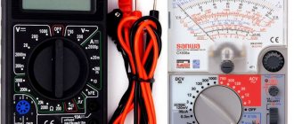
The main measuring instruments include ammeter, voltmeter and ohmmeter. As a rule, devices take up quite a lot of space on the desktop. The way out of this situation is to purchase a multimeter (tester). The digital device replaces all three devices at once.
What is a multimeter
The tester is equipped with a liquid crystal screen. The device measures variable and constant characteristics of currents in different ranges. The universal device can measure direct and alternating voltage, direct current, and resistance value. A multimeter is used to test diodes and capacitors, as well as other radio elements.
On the front panel there are:
- LCD display. It shows the magnitude values of various current characteristics in a digital image.
- In the center there is a rotating disk with a pointer. It is installed opposite the mark of the required measurement mode.
- The following symbols are located around the disk:
- OFF – the device is turned off;
- ACV – alternating voltage measurement;
- DCV – the same constant voltage;
- DCA – direct current measurement;
- Ω – resistance measurement.
- The tip of the black wire is inserted into the COM socket.
- The “10ADC” socket of the red wire is used to measure voltage or current up to 10 amperes.
- The “VRmA” connector is used to measure currents up to 200 mA.
- To determine the resistance, use the socket with the “Ω” sign.
- The terminal hole under the “▬►▌▬” sign is used to test the electrical circuit for breaks.
Multimeter
Important! When using devices, you must remember that the black wire must always be connected to the COM socket with the “-” sign. If the probes are swapped in places, the fuse of the measuring device will burn out.
Tools and materials
The radio amateur's workbench must be equipped with the necessary tools and materials.
Tools
The most necessary tools make up the following set:
- Soldering iron.
- Induction soldering station.
- Soldering hair dryer.
- Related devices.
Soldering iron
The main tool of a radio technician is a soldering iron. Without mastering the art of soldering circuits and radio components, it is impossible for beginning radio amateurs to comprehend the basics of radio engineering. For a beginner, it is better to start using a pulse soldering iron right away.
The power tool almost instantly heats up to the melting temperature of the solder. Its tip in the form of a curved wire allows you to apply molten metal exactly to the soldering site.
Induction soldering station
The station is equipped with a soldering iron, which does not have a transmitting heating element. The ferromagnetic surface of the tip is a continuation of the monolithic copper core. The end of the rod enters the induction coil.
The station system is designed to constantly maintain the heating level of the soldering iron tip. This allows you to avoid unnecessary energy consumption and prevent overheating in the soldering area.
Having reached a certain temperature level, the ferromagnetic shell of the core ceases to perceive the alternating magnetic field of the induction coil, and the tip begins to cool. The temperature drop restores the properties of the ferromagnetic coating, and heating of the core resumes.
Soldering gun
A hot air gun for radio amateurs appeared relatively recently. The device pumps hot air through a narrow nozzle into the soldering area. Its temperature reaches the melting level of solder. Using a soldering gun, you can easily remove soldering or mount a radio component on a printed circuit board.
A spiral of nichrome wire covers the air duct cylinder. To avoid heat loss, the spiral is wrapped on top with mica or other heat insulator. The air flow is created by a built-in fan.
Hot air gun
Related accessories
To fix parts, various clamps, mini-vices and clamps are used. Platforms are made from a wooden plank, in which recesses for cups for candles are cut out with a milling cutter. They are filled with flux, solder and copper shavings to clean the soldering iron tip. A set of needle files, wire cutters and a scalpel are always useful in the work of a radio amateur.
Materials
Here is a sample list of materials for a novice radio technician:
- textolite for the manufacture of printed circuit boards;
- pickling liquid;
- solder and flux;
- napkins or copper shavings.
Chapter 1 Lessons from a young designer
Is it possible to drive a car without knowing how to start the engine and what the pedals and control handles are for?
Of course not, you say. First you need to familiarize yourself with the purpose of each handle, learn the structure of the car, and then drive it. It’s the same with our designs. They use a variety of parts, each of which performs its own predetermined function. To create any device, you need to know what the parts included in it are needed for, be able to check them, connect them to each other, and adjust the created structure.
This section will help you gain basic knowledge about electric current, radio components and the rules for creating products. Of course, not all the information contained in it will be clear after the first reading. Don't worry - practice will help you! The main thing is to learn the work safety rules well and take it on boldly. Please refer to these materials, which are mainly for informational purposes, if you have any questions.