Protective grounding device is a method of electrically connecting a protective conductor to non-current-carrying enclosures of electrical installations exposed to phase short-circuit currents. A protective circuit, the main task of which is to prevent electrical injuries associated with peak current values during a short circuit.
To understand the essence of the device, you should know the basic theoretical issues.
What acts as an artificial grounding conductor
The grounding element is made in the form of a conductor (electrode) of a certain material, which is placed in the ground.
In some cases, several similar grounding conductors are installed. Determining the situation when it is necessary to install a group of artificial rods is realized through special calculations. The result of the calculation justifies the choice of electrode configuration in relation to its resistance - the main indicator that determines the quality of grounding.
An artificial ground electrode is made from the following materials:
- Copper-plated steel. The connection between copper and steel has good adhesion. The rods are durable and have excellent contact with any materials. Due to its chemical properties, the alloy has excellent electrical conductivity. The electrochemical activity of copper and steel is insignificant; normal operation of ground electrodes made of such metal can reach more than a hundred years.
- Cink Steel. Advantages: corrosion resistance of the material, low resistance, electrodes are resistant to acidic environments.
- Black metals. Disadvantage: rapid destruction in aggressive soil (corrosion and rust form). The high strength of the material increases the resistance to current spreading, which is extremely dangerous for humans.
In addition to the material, artificial ground electrodes differ in shape and location in the soil (deep vertical and extended horizontal type).
DIY grounding installation
The location is chosen so that there are no communications on the site. Before making grounding at the dacha with your own hands, coordinate the scheme with the water supply, gas service and other offices. Grounding is done more often on the north side of the house, since there is always a more humid place on the site.
Mount the circuit according to the rules:
- dig a trench for horizontal connections;
- pins are hammered into the corners of a triangle with equal sides;
- You cannot dig holes for the rods; the rods must fit tightly into the ground;
- weld the strip to the corners, attach a conductive cable going to the building;
- After joining, welding areas are treated with melted bitumen (resin);
- bury the installation site.
Check grounding using a multimeter. The socket is opened in the house, the device is switched to voltage regulation. After connecting the zero and phase probes, the multimeter should show voltage. Then the phase and ground are connected, and the voltage should drop slightly.
PUE REQUIREMENTS FOR THE ARRANGEMENT AND QUALITY OF GROUNDING
To implement such protection against electric shock, it is necessary to ensure reliable contact of the electrical installation housing with the ground.
In its presence, a current charge dangerous to humans flows into the ground through a grounding device, the resistance of which is significantly lower than that of the human body.
TYPES OF GROUNDING DEVICES
According to the requirements of the PUE, electrical equipment enclosures must be grounded to ensure safety. For this purpose, various types of grounding conductors are used.
The following can be used as ready-made ones:
- metal structures laid in the ground and in direct contact with it;
- metal casings and sheaths of cables laid in the ground for specific purposes;
- metal pipelines (except for gas communications and oil pipelines);
- railway rails.
The use of ready-made structures as grounding conductors significantly simplifies and reduces the cost of arranging the entire system.
Specially mounted grounding devices are used when it is not possible to use underground pipes, cable communications or metal structural elements.
They are various structural elements placed in the ground at a certain depth and ensuring reliable contact with the soil.
The simplest version of such a ground electrode is a steel rod at least 2.5 meters long. After it is buried, a thick copper conductor (steel strip) is attached to the tip and connected to the grounding system.
GROUNDING RESISTANCE
The main requirement for a grounding device, regardless of its type, is to provide conditions for the flow of charges dangerous to humans into the soil. Its functionality is assessed by its spreading resistance (the lower it is, the more effective the grounding is).
The main components are resistances:
- the ground electrode itself;
- transitional (contact) between the ground electrode and the ground;
- soil at the point of contact with the grounding device.
According to the PUE, the resistance of a typical device installed on the consumer side should not exceed 30 Ohms. Under special operating conditions of equipment (at power substations, in particular), it is standardized at a level of no more than 4 ohms.
It is possible to achieve standardized indicators by taking special measures. As a rule, they come down to the following techniques:
- increasing the contact area of artificial grounding elements with the ground;
- improving soil conductivity (by moistening or adding chemicals).
In addition, the requirements of the PUE require periodic measurements of grounding resistance for compliance with current standards.
* * *
2014-2021 All rights reserved. The materials on the site are for informational purposes only, may express the opinion of the author and are not to be used as guidelines or normative documents.
Design features
As mentioned above, the basic design element is the grounding rods. Their number, material, diameter and length depend on the installation conditions and the soil resistivity to current spreading. The higher the resistance, the greater the total length and/or diameter, the greater the number of installation points for grounding electrodes.
The rods have threads at the ends and are connected to each other by means of couplings. At the same time, to ensure better conductivity in the places where they are installed, the constructs are lubricated with conductive lubricant (paste).
Foreign manufacturers use a trunnion-type couplingless connection; it is more contact and does not need to be lubricated with paste. That is, a self-closing structure is obtained (the example below shows a cut at the junction).
To facilitate installation in the ground, the kits include tips and impact heads. Manufacturers from Russia make these components with threads, while foreign ones eliminate the risks arising from threaded contact, especially when hammering, and connect the elements securely into a joint.
At the point where the last (upper) grounding conductor exits, the entire structure is connected using a clamp to a lightning protection system or grounding bus
The geometry of the clamp does not matter (diagonal or cross), it is only important that its material, in terms of corrosion, does not “conflict” with the material of the grounding conductors and grounding conductors
Grounding Requirements
After you have figured out what is the definition of the very concept of grounding, you can move on to those categories and norms that are introduced by current standards. According to the PUE, the grounding device is primarily subject to the following requirements:
- the purpose of the charger is to effectively drain dangerous currents into the ground, for which purpose their design includes a whole set of conductors and metal rods;
- All parts of the electrical installation, including metal switchboard doors, must be grounded;
- the total contact resistance of the contacts in the grounding system should not exceed 4-30 Ohms;
- when installing it in distributed loads, it is necessary to use a potential equalization system (its purpose is to eliminate uneven voltage distribution).
Additional information: Since the main purpose of grounding is to ensure the safety of personnel working with the equipment, during its operation special attention is paid to the reliability of operation. The quality of its work is ensured by a whole range of preventive measures and periodically organized tests.
Grounding and grounding.
Types of designs
Using incorrectly connected electrical appliances can be unsafe. The danger is that during use a breakdown may occur, as a result of which the voltage will transfer to the device body. This voltage can either damage the device itself or cause electrical injury of varying severity to a person (including death). To prevent such problems, two types of grounding can be used:
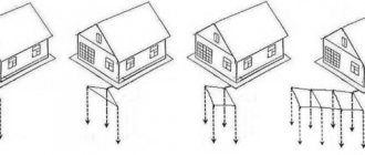
- Natural. This includes massive structures that are permanently in the ground. The role of natural grounding conductors is given to the foundations of buildings, water pipes, metal structures and sheet piles, well fixed in the ground. The advantage of such structures is that providing grounding with their help does not require additional costs. However, natural loop resistance cannot be calculated.
- Artificial. Grounding of this kind is created specifically from horizontal and vertical elements (electrodes) made of a certain material and having a specific size. The main elements of the artificial contour are most often steel parts that have a round or angular shape. The quality of such grounding depends on the resistance possessed by artificial ground electrodes. The resistance of each electrode is determined using a special formula.
All modern devices powered by electricity are grounded. All that needs to be done is simply to provide a connection to the main grounding system.
Galvanizing methods
The most effective and convenient method is hot-dip galvanizing, in which the steel part is briefly dipped into a bath of molten zinc. As a result, under the influence of high temperature, a thin ferrum-zinc film appears on the surface. And since zinc is resistant to moisture, its properties (with uniform and continuous distribution over the entire surface) extend to the entire steel part.
An additional advantage is that hot-dip galvanizing does not have to be carried out immediately after strip production. For it, metal products already in stock and even entire welded structures can be used, provided that they can be lowered into a container with zinc.
The main disadvantage of this method of protection is the complexity of installation, since it is impossible to weld individual galvanized parts without damaging the protective layer. Damaged areas, in turn, will become hotbeds for corrosion. The only methods for installing a grounding loop from a steel strip in this case are:
What are the requirements for artificial grounding conductors?
Artificial grounding conductors cannot be painted, since painting acts as an insulator and prevents the discharge of electric current into the ground. Thus, the color of the grounding conductor should be the natural color of the metal used in grounding devices. But the connection points of the conductors (welding seams) must be painted with bitumen paint to prevent destruction.
You cannot place artificial or use natural grounding electrodes near heat sources that dry out the earth. For arid areas there is a special reinforced concrete structure. The ground electrode is made in the form of a container and placed below the surface of the earth. The container is filled with water through the hatch. Thus, the water distribution system takes part in grounding. Steel electrodes are connected to the outlet from the container. This ensures optimal resistance.
To create artificial grounding conductors, the following materials with the specified parameters are used:
- the diameter of the steel reinforcing bar is at least 10 mm;
- the diameter of the galvanized rod is at least 6 mm;
- in the corners the wall thickness is from 4 mm;
- when using strip steel, its thickness must be at least 4 mm;
- in lightning protection grounding conductors, the cross-section is taken from 155 mm2;
- The wall thickness of rejected pipes is at least 3.5 mm.
Only for temporary electrical installations can electrodes with minimum values be used. In order for the grounding device to serve for 40-50 years in favorable soil conditions, it is enough to select rods for it that are 2-3 mm larger. In wet soils, the thickness and diameters of the pads should be 2 times higher than the minimum.
Of all the mentioned materials, the use of round reinforcement is considered the most optimal, since the metal consumption in this case is reduced by 1.5 times, and the cost of grounding devices is correspondingly reduced.
The corrosion resistance of round steel is higher than that of linear steel, because the round electrode has the smallest contact area with the ground compared to other forms of electrode. Another advantage is that round rod electrodes are easier to install, saving time spent on charging devices.
When grounding powerful high-voltage installations, circuits are used consisting of horizontal beams extending over hundreds of meters and several dozen vertically installed rods. To prevent artificial ground electrodes from shielding each other, the beams are spread horizontally in opposite directions. If there are 3 or 4 rays, they are placed at an angle of 90 and 120 degrees, respectively.
What color should artificial ground electrodes be painted?
⇐ PreviousPage 10 of 14Next ⇒
| To black | Incorrect answer |
| In blue | Incorrect answer |
| Green with yellow stripes | Incorrect answer |
| They should not be colored | Correct answer |
In what electrical installations are dielectric galoshes used?
| In electrical installations with voltages up to 1000 V | Correct answer |
| In electrical installations with voltages over 1000 V | Incorrect answer |
| In electrical installations with voltages up to 10,000 V | Incorrect answer |
| In all electrical installations | Incorrect answer |
What type of safety poster is a poster that says “Grounded”?
| To those prohibiting | Incorrect answer |
| To the warnings | Incorrect answer |
| Towards prescriptive | Incorrect answer |
| To the index fingers | Correct answer |
What should be done first if a person is injured by electric shock?
| Call an ambulance | Incorrect answer |
| Turn off the electric current | Correct answer |
| Pull the victim by his clothes at least 8 meters from the place where the wire touches the ground or from live equipment | Incorrect answer |
| Begin resuscitation of the victim | Incorrect answer |
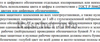
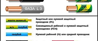
Ticket 23. What letter and color designations should tires have for three-phase alternating current?
| Buses of phase A - yellow, phase B - green, phase C - red | Correct answer |
| Buses of phase A - green, phase B - yellow, phase C - red | Incorrect answer |
| Busbars of phase A - red, phase B - white, phase C - blue | Incorrect answer |
| Buses of phase A - blue, phase B - white, phase C - red | Incorrect answer |
How long does it take to carry out comprehensive testing of the main and auxiliary equipment of an electrical installation before putting it into operation?
| Within 24 hours | Incorrect answer |
| Within 48 hours | Incorrect answer |
| Within 72 hours | Correct answer |
| Within 120 hours | Incorrect answer |
What is the frequency of testing electrical safety knowledge for personnel servicing electrical installations?
| At least once a year | Correct answer |
| At least once every two years | Incorrect answer |
| At least once every three years | Incorrect answer |
| At least once every five years | Incorrect answer |
For what period is a work order issued for work on electrical installations?
| No more than 5 calendar days from the date of commencement of work | Incorrect answer |
| No more than 10 calendar days from the date of commencement of work | Incorrect answer |
| No more than 15 calendar days from the date of commencement of work | Correct answer |
| No more than 20 calendar days from the date of commencement of work | Incorrect answer |
| For the entire duration of the work | Incorrect answer |
Which of the listed works can be classified as work performed as part of routine operation in electrical installations with voltages up to 1000 V?
| Removal and installation of electricity meters, other instruments and measuring instruments | Correct answer |
| Repair of starting and switching equipment installed on panels | Incorrect answer |
| Replacing lamps and cleaning luminaires at a height of more than 2.5 m | Incorrect answer |
| Any of the listed works | Incorrect answer |
What color should exposed grounding conductors be painted?
Use the site search:
Deepening the electrodes
The electrodes are driven into the ground by driving them with a sledgehammer. To make work easier, it is better to use a scaffold or stepladder. If the metal of the electrodes is too soft, then the blows are delivered through special wooden bars. There is no need to drive the pins in completely: about 10-20 centimeters should remain above the ground, which are used to connect to the circuit.
The factory electrodes are driven in with a jackhammer. After the pin is deepened, a coupling and an additional grounding conductor are screwed onto it. The process is repeated several times until the required depth is achieved.
Types of grounding
In the classification of types of grounding there are two main types:
- Working.
- Protective.
There are several subgroups: radio grounding, measuring, instrumental, control.
Working
There is a certain category of electrical installations that will not work unless they are grounded. That is, the main purpose of constructing a grounding system is not to ensure operational safety, but to ensure the operation itself. Therefore, in this article we will not be interested in this species.
Protective
But this type is specially arranged to ensure the safety of electrical installations. It is divided into three categories depending on its purpose:
- Lightning protection.
- Protection against surge voltage (overload of current consumption line or short circuit).
- Protection of the electrical network from electromagnetic interference (most often this type of interference is generated from nearby operating electrical equipment).
We are interested in pulse overvoltage. The purpose of this type of grounding is the safety of operating personnel and the installation itself in the event of an accident or equipment breakdown. Typically, such a breakdown inside an electrical unit is a short circuit of the electrical circuit wire to the device body. The short circuit can occur directly or through any other conductor, for example, through water. A person who touches the installation body is exposed to electric current, because he becomes its conductor into the ground. In fact, it itself becomes part of the ground loop.
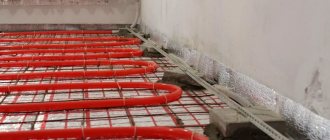
Grounding diagram in a private house
That is why, in order to eliminate such situations, the housing is grounded to a circuit located in the ground. At the same time, the activation of the grounding circuit is an impetus for the system of automatic machines, which immediately turn off the power supply to the equipment. All this is located in special power and distribution boards.
Ground resistance
There is such a term as resistance to current flow. For ordinary people it will be easier to perceive it as resistance to grounding. The whole point of this term is that the grounding circuit must work correctly within certain parameters. So resistance is the main one.
The optimal option for this value is zero. That is, it is best to use materials for assembling the circuit that have the highest electrical conductivity. Of course, there is no way to achieve the ideal, so try to choose those with the lowest resistance. These include all metals.
There are special coefficients that are used to determine the resistance of a grounding loop operated under different conditions. Eg:
in private housing construction, where networks of 220 and 380 volts (6 and 10 kV) are used, it is necessary to install a circuit with a resistance of 30 Ohms.
- the installed gas pipeline system entering the house must be grounded with a 10 ohm circuit.
- lightning protection must have a resistance of no more than 10 ohms.
- Telecommunications equipment is grounded using a 2 or 4 ohm loop.
- Substations from 10 kV to 110 kV – 0.5 Ohm.
That is, it turns out that the greater the current power inside the equipment or devices, the lower the resistance should be.
Galvanizing methods
The most effective and convenient method is hot-dip galvanizing, in which the steel part is briefly dipped into a bath of molten zinc. As a result, under the influence of high temperature, a thin ferrum-zinc film appears on the surface. And since zinc is resistant to moisture, its properties (with uniform and continuous distribution over the entire surface) extend to the entire steel part.
An additional advantage is that hot-dip galvanizing does not have to be carried out immediately after strip production. For it, metal products already in stock and even entire welded structures can be used, provided that they can be lowered into a container with zinc.
The main disadvantage of this method of protection is the complexity of installation, since it is impossible to weld individual galvanized parts without damaging the protective layer. Damaged areas, in turn, will become hotbeds for corrosion. The only methods for installing a grounding loop from a steel strip in this case are:
What is a ground electrode and what can be used as a ground electrode?
What is a ground electrode?
GROUNDING LEADER - a conductive part (or a set of interconnected conductive parts) that is in contact with the ground directly or through an intermediate conductive medium.
What can a grounding conductor be made from?
1.7.109. The following can be used as natural ground electrodes: 1) metal and reinforced concrete structures of buildings and structures in contact with the ground, including reinforced concrete foundations of buildings and structures that have protective waterproofing coatings in non-aggressive, slightly aggressive and moderately aggressive environments; 2) metal water pipes laid in the ground; 3) casing pipes of boreholes; 4) metal sheet piles of hydraulic structures, water conduits, embedded parts of valves, etc.; 5) rail tracks of main non-electrified railways and access roads if there is a deliberate arrangement of jumpers between the rails; 6) other metal structures and structures located in the ground; 7) metal shells of armored cables laid in the ground. Cable sheaths can serve as the only grounding conductors when there are at least two cables. Aluminum cable sheaths are not allowed to be used as grounding conductors.
What cannot be used as a grounding conductor?
1.7.110. It is not allowed to use pipelines of flammable liquids, flammable or explosive gases and mixtures, and sewerage and central heating pipelines as grounding conductors. The specified restrictions do not exclude the need to connect such pipelines to a grounding device for the purpose of equalizing potentials in accordance with 1.7.82. Reinforced concrete structures of buildings and structures with prestressed reinforcement should not be used as grounding conductors, however, this restriction does not apply to overhead line supports and outdoor switchgear support structures. The possibility of using natural grounding conductors based on the density of currents flowing through them, the need to weld reinforcing bars of reinforced concrete foundations and structures, welding anchor bolts of steel columns to reinforcing bars of reinforced concrete foundations, as well as the possibility of using foundations in highly aggressive environments must be determined by calculation.
Requirements for artificial grounding conductors?
1.7.111. Artificial grounding conductors can be made of black or galvanized steel or copper. Artificial grounding conductors should not be painted. 1.7.112. The cross-section of horizontal grounding conductors for electrical installations with voltages above 1 kV should be selected according to the condition of thermal resistance at a permissible heating temperature of 400 °C (short-term heating corresponding to the duration of the protection and tripping of the circuit breaker). In case of danger of corrosion of grounding devices, one of the following measures should be taken: increase the cross-sections of grounding conductors and grounding conductors, taking into account their estimated service life; use galvanized or copper grounding conductors and grounding conductors. In this case, one should take into account the possible increase in the resistance of grounding devices due to corrosion. Trenches for horizontal grounding conductors must be filled with homogeneous soil that does not contain crushed stone and construction waste. Grounding electrodes should not be located (used) in places where the ground is dried out by the heat of pipelines, etc.
Chapter 2.7. Grounding devices
2.7.1. This chapter applies to all types of grounding devices, potential equalization systems, etc. (hereinafter referred to as grounding devices). 
2.7.2. Grounding devices must comply with the requirements of state standards, rules for electrical installations, building codes and regulations and other regulatory and technical documents, ensure conditions for the safety of people, operating modes and protection of electrical installations. 
2.7.3. Admission to operation of grounding devices is carried out in accordance with established requirements. 
When commissioning a grounding device, the installation organization must provide documentation in accordance with established requirements and rules. 
2.7.4. The connection of grounding conductors to the grounding conductor and grounding structures must be made by welding, and to the main grounding clamp, housings of devices, machines and overhead line supports - by bolting (to ensure the possibility of making measurements). Contact connections must meet the requirements of state standards. 
2.7.5. Installation of grounding conductors, grounding conductors, connection of grounding conductors to grounding conductors and equipment must comply with the established requirements. 
2.7.6. Each part of the electrical installation that is subject to grounding or grounding must be connected to the grounding or grounding network using a separate conductor. The serial connection of several elements of an electrical installation with grounding (neutral) conductors is not allowed. 
The cross-section of grounding and neutral protective conductors must comply with the rules for electrical installations. 
2.7.7. Openly laid grounding conductors must be protected from corrosion and painted black. 
2.7.8. To determine the technical condition of the grounding device, visual inspections of the visible part, inspections of the grounding device with selective opening of the soil, and measurement of the parameters of the grounding device must be carried out in accordance with the electrical equipment testing standards (Appendix 3). 
2.7.9. Visual inspections of the visible part of the grounding device must be carried out according to a schedule, but at least once every 6 months, by the person responsible for the electrical equipment of the Consumer or an employee authorized by him. 
During the inspection, the condition of the contact connections between the protective conductor and the equipment, the presence of anti-corrosion coating, and the absence of breaks are assessed. 
2.7.10. Inspections with selective opening of the soil in places most susceptible to corrosion, as well as near the grounding points of power transformer neutrals, connections of arresters and surge arresters must be carried out in accordance with the schedule of planned preventive maintenance (hereinafter referred to as PPR), but at least once every 12 years. The size of the section of the grounding device subject to selective excavation of the soil (except for overhead lines in populated areas - see clause 2.7.11) is determined by the decision of the technical manager of the Consumer. 
2.7.11. Selective opening of the soil is carried out on all grounding devices of the Consumer's electrical installations; for overhead lines in populated areas, opening is carried out selectively at 2% of supports that have grounding devices. 
2.7.12. In areas with highly aggressive soil, by decision of the technical manager of the Consumer, a more frequent inspection frequency with selective opening of the soil may be established. 
When opening the pound, an instrumental assessment of the condition of the grounding conductors and an assessment of the degree of corrosion of the contact connections must be made. The grounding element must be replaced if more than 50% of its cross-section is destroyed. 
The results of inspections must be documented. 
2.7.13. To determine the technical condition of the grounding device in accordance with the electrical equipment testing standards (Appendix 3), the following must be carried out: 
For overhead lines, measurements are made annually at supports that have disconnectors, protective gaps, arresters, re-grounding of the neutral wire, as well as selectively at 2% of reinforced concrete and metal supports in populated areas. 
Measurements should be carried out during the period of greatest drying of the soil (for permafrost areas - during the period of greatest freezing of the soil). 
The measurement results are documented in protocols. 
At the main step-down substations and transformer substations, where disconnecting the grounding conductors from the equipment is impossible due to the conditions for ensuring the category of power supply, the technical condition of the grounding device must be assessed based on the measurement results and in accordance with paragraphs 2.7.9-11. 
2.7.14. Measurements of the parameters of grounding devices - resistance of the grounding device, touch voltage, checking the presence of a circuit between grounding conductors and grounded elements - are also carried out after reconstruction and repair of grounding devices, when destruction or overlap of overhead line insulators by an electric arc is detected. 
If necessary, measures must be taken to bring the parameters of grounding devices up to standard. 
The results of visual inspections, inspections with opening of the soil, protocols for measuring the parameters of the grounding device, data on the nature of repairs and changes made to the design of the device must be attached to the passport. 
2.7.16. To check whether the melting currents of fuses or settings of circuit breakers releases correspond to the short circuit current in electrical installations, the protection operation must be checked. 
2.7.17. After each rearrangement of electrical equipment and installation of a new one (in electrical installations up to 1000 V), before turning it on, it is necessary to check the operation of the short circuit protection. 
2.7.18. The use of earth as a phase or neutral wire in electrical installations up to 1000 V is not allowed. 
2.7.19. When using residual current devices (hereinafter referred to as RCDs) in an electrical installation, they must be checked in accordance with the manufacturer’s recommendations and electrical equipment testing standards (Appendix 3). 
2.7.20. Networks up to 1000 V with an isolated neutral must be protected by a blow-out fuse. The fuse can be installed in the neutral or phase on the low voltage side of the transformer. At the same time, control over its integrity must be provided. 
Source
What acts as an artificial grounding conductor
The grounding element is made in the form of a conductor (electrode) of a certain material, which is placed in the ground. In some cases, several similar grounding conductors are installed.
Determining the situation when it is necessary to install a group of artificial rods is realized through special calculations. The result of the calculation justifies the choice of electrode configuration in relation to its resistance - the main indicator that determines the quality of grounding.
An artificial ground electrode is made from the following materials:
- Copper-plated steel. The connection between copper and steel has good adhesion. The rods are durable and have excellent contact with any materials. Due to its chemical properties, the alloy has excellent electrical conductivity. The electrochemical activity of copper and steel is insignificant; normal operation of ground electrodes made of such metal can reach more than a hundred years.
- Cink Steel. Advantages: corrosion resistance of the material, low resistance, electrodes are resistant to acidic environments.
- Black metals. Disadvantage: rapid destruction in aggressive soil (corrosion and rust form). The high strength of the material increases the resistance to current spreading, which is extremely dangerous for humans.
In addition to the material, artificial ground electrodes differ in shape and location in the soil (deep vertical and extended horizontal type).
Resistance of artificial ground electrode
In order for the charger to effectively perform its task, it must have a spreading resistance that does not exceed certain values. This parameter shows how well the device conducts electric current.
For a grounded electrical installation with a voltage of 380V, the resistance of the artificial ground electrode should not exceed 30 Ohms. Operating under high voltage, medical equipment, server units, video surveillance systems are grounded with a resistance of 0.5-1 Ohm.
Calculation for artificial grounding conductors is carried out in order to determine how many vertical and horizontal conductive rods should be installed to obtain optimal resistance.
Electrode placement
The parts included in the general grounding structure can be located vertically or horizontally. In the first installation method, the electrodes are buried 70 cm into the ground. However, their length should not exceed 5 m, and their diameter should be in the range of 10-16 mm.
The horizontal laying method involves deepening the grounding bars by 50 cm (in the case of arable land by 1 m). Horizontally located steel rods with a diameter of more than 1 cm (or steel strips with a thickness of more than 4 mm) are used to connect vertically installed elements, the joints between them are fixed by welding. This method shows its effectiveness only if there is sufficient electrical conductivity of the top layer of soil.
Electrical installation rules require grounding for electrical equipment for domestic and industrial purposes. There are no clear requirements regarding how the electrodes should be located in the ground. In each specific case this is determined individually.
You might be interested in: Types of single-pole and double-pole voltage indicators up to 1000 V
Electrical safety created with the help of artificial grounding conductors is realized by reducing the potential difference and removing stray current. Leakage current occurs due to the interaction of the grounding element and the phase cable. At the same time, uninterrupted and efficient functioning of electrical equipment is ensured.
What color should artificial ground electrodes be painted?
⇐ PreviousPage 10 of 14Next ⇒
| To black | Incorrect answer |
| In blue | Incorrect answer |
| Green with yellow stripes | Incorrect answer |
| They should not be colored | Correct answer |
In what electrical installations are dielectric galoshes used?
| In electrical installations with voltages up to 1000 V | Correct answer |
| In electrical installations with voltages over 1000 V | Incorrect answer |
| In electrical installations with voltages up to 10,000 V | Incorrect answer |
| In all electrical installations | Incorrect answer |
What type of safety poster is a poster that says “Grounded”?
| To those prohibiting | Incorrect answer |
| To the warnings | Incorrect answer |
| Towards prescriptive | Incorrect answer |
| To the index fingers | Correct answer |
What should be done first if a person is injured by electric shock?
| Call an ambulance | Incorrect answer |
| Turn off the electric current | Correct answer |
| Pull the victim by his clothes at least 8 meters from the place where the wire touches the ground or from live equipment | Incorrect answer |
| Begin resuscitation of the victim | Incorrect answer |
Ticket 23. What letter and color designations should tires have for three-phase alternating current?
| Buses of phase A - yellow, phase B - green, phase C - red | Correct answer |
| Buses of phase A - green, phase B - yellow, phase C - red | Incorrect answer |
| Busbars of phase A - red, phase B - white, phase C - blue | Incorrect answer |
| Buses of phase A - blue, phase B - white, phase C - red | Incorrect answer |
How long does it take to carry out comprehensive testing of the main and auxiliary equipment of an electrical installation before putting it into operation?
| Within 24 hours | Incorrect answer |
| Within 48 hours | Incorrect answer |
| Within 72 hours | Correct answer |
| Within 120 hours | Incorrect answer |
What is the frequency of testing electrical safety knowledge for personnel servicing electrical installations?
| At least once a year | Correct answer |
| At least once every two years | Incorrect answer |
| At least once every three years | Incorrect answer |
| At least once every five years | Incorrect answer |
For what period is a work order issued for work on electrical installations?
| No more than 5 calendar days from the date of commencement of work | Incorrect answer |
| No more than 10 calendar days from the date of commencement of work | Incorrect answer |
| No more than 15 calendar days from the date of commencement of work | Correct answer |
| No more than 20 calendar days from the date of commencement of work | Incorrect answer |
| For the entire duration of the work | Incorrect answer |
Which of the listed works can be classified as work performed as part of routine operation in electrical installations with voltages up to 1000 V?
| Removal and installation of electricity meters, other instruments and measuring instruments | Correct answer |
| Repair of starting and switching equipment installed on panels | Incorrect answer |
| Replacing lamps and cleaning luminaires at a height of more than 2.5 m | Incorrect answer |
| Any of the listed works | Incorrect answer |
What color should exposed grounding conductors be painted?
Use the site search: