Theorists
First, let's define the purpose of this part, as well as the basic concepts and terms associated with it.
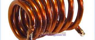
What is an inductor
Variety of reel sizes
An inductor is a radio element used in various circuits for the following:
- Beat smoothing;
- Interference suppression;
- AC current limitation;
- Energy storage and more.
This element is a spiral, screw or helical coil made of an insulated conductor. The part has a relatively small capacitance and low active resistance, while it has high inductance, that is, the ability to generate EMF (electromotive force) in the conductor when electric current flows in the circuit.
Chokes on a printed circuit board
- The inductor, depending on the place and purpose of application, may have other names. For example, if an element is used for high-frequency isolation in different parts of the circuit, storing the energy of the magnetic field of the core, smoothing out ripples and suppressing interference, the coil is called a choke or a reactor (the second name is rarely used).
- If we talk about power electrical engineering, then the name rector has been established - it is used when it is necessary to limit the current, for example, if there is a short circuit on a power line.
Solenoid
- There are also cylindrical inductors called solenoids. The length of such a cylinder is several times greater than its diameter.
Interesting to know! The magnetic field inside the solenoid is uniform. This magnetic field can perform mechanical work by drawing in the ferrite core.
Coil from the solenoid relay on the starter
- Inductors are also used in electromagnetic relays, where they are called relay windings.
- Similar elements are also installed in induction heaters - here they are called heating inductors.
Diagram of a superconducting inductive storage device
- You can also hear terms like induction storage or storage choke when talking about pulsed voltage stabilization devices.
Design features
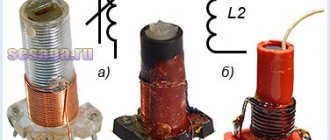
The structure of the inductor
Structurally, the inductor is an insulated single-core or stranded conductor (usually varnished copper wire) wound in a spiral or screw around a dielectric core (frame). The core shape can be round, toroidal, rectangular, square. The materials used for the core have a magnetic permeability higher than that of air, which additionally retains the magnetic field near the coil, which means the inductance increases.
There are also coils that do not have a core at all, or it is adjustable, which allows you to change the inductance of the part.
Toroidal coil
The winding of the conductor can be single-layer, it is also called ordinary with a step, or multi-layer (the names universal, pile-on, ordinary are used). The distance between the turns is called the pitch.
Interesting to know! The winding pitch can be progressive, that is, its value varies along the length of the coil. This winding is used to reduce the “parasitic” capacitance.
Application
Coils are used in signal processing and analog circuits. When combined with capacitors and other radio components, they can form sections of circuitry that amplify or filter certain signals.
Chokes are widely used in power supplies, where they, together with filter capacitors, are designed to eliminate residual noise and other fluctuations that occur at the output.
Transformer structure
If two coils are connected by one magnetic field, you get a transformer - a device capable of transmitting electricity from one part of the circuit to another, due to electromagnetic induction, simultaneously changing the voltage value.
For reference! Transformers are capable of operating only with alternating current.
Main characteristics of inductors
Before we understand how current behaves when passing through an inductor in a circuit, let's first find out the main characteristics of this element.
Definition of inductance: formula
- First of all, we are interested in inductance - a value expressed numerically by the ratio of the magnetic field flux, which is created by the flowing current, to the strength of this current itself. This parameter is measured in Henry (H).
- In simpler terms, this phenomenon can be described as follows. When current flows through the inductor, an electromagnetic field is created, which is directly related to the emf, which counteracts the change in alternating voltage, that is, a current appears in the circuit that flows in the opposite direction to the main one.
- Measuring the current strength on the inductor and alternating voltage resist this force, or rather the opposite. This property of the element is called inductive reactance, which is in antiphase to the capacitive reactance of a capacitor connected to an alternating current circuit.
Advice! The change in the inductance of the coil occurs in proportion to the change in the number of turns.
Calculation of coil magnetic field energy
- It has long been known that any magnetic field has some energy. It follows that the magnetic field of the coil also has a certain supply of magnetic energy. The value of this reserve is equal to the energy expended to ensure the flow of current (I) in opposition to the EMF. Calculations are made using the above formula.
Hydro turbine
- To make it even clearer, let's compare a coil with a hydraulic turbine. So, the water flow that is directed through the turbine will feel its resistance until the turbine spins up completely. It has some inertia, which means it will rotate synchronously with the flow of water, without providing practically any resistance to it.
- If you try to stop the flow of water or change its direction, you will see that the turbine will continue to rotate by inertia, forcing the water to move in the same direction. The higher the inertia of the turbine, the more it will resist changing the direction of water flow.
- Exactly the same thing happens in an inductor when alternating current begins to flow in the opposite direction.
When coils are connected in series, their inductance adds up
- The influence of current on the inductance of the coil is expressed not only in the form of the main interaction effect. Parasitic effects are often observed, due to which the alternating current resistance of the inductor cannot be called purely reactive. Due to these effects, some losses occur in the coil, which are measured as loss resistance. This value is the sum of losses in the core, wire, screen and dielectric.
- Each loss is caused by different reasons. There are three of them in the wires: they have, although small, but still active ohmic resistance; this resistance increases with increasing frequency, which is due to a decrease in the amplitude of electromagnetic waves as they penetrate deep into the conducting medium (this phenomenon is called the skin effect) - in other words, the current is displaced to the upper layers of the wire, due to which the area of the conductor changes , and therefore its resistance; if the wires are twisted into a spiral, a proximity effect occurs, due to which the active cross-section of the conductor and the overall resistance also change.
Welding machine choke
- Losses in the dielectric may arise due to the interturn capacitor, or due to its electromagnetic properties. However, in fairness, it is worth noting that the losses in this part of the part are so small that they are often neglected in calculations.
- Losses on the core consist of two quantities: losses due to magnetization reversal of the ferromagnet (losses due to hysteresis) and losses due to eddy currents. The alternating magnetic field arising from the current flowing in the conductor induces eddy EMF in neighboring conductors - the core, the wires of the nearest turns, and even the screen. The resulting currents, which have a name in addition to eddy currents, Foucault currents, also cause losses due to the active resistance of the wire.
- Another characteristic called quality factor is also associated with resistance losses. Its value is the ratio of the reactive and active resistance of the inductor.
Parasitic inductor capacitance
- The next parameter is parasitic capacitance. The phenomenon is that some unwanted capacitive coupling occurs between the turns of the coil.
- TCI (temperature coefficient of inductance) - we all know that when heated, substances increase in size. When this happens to the coil, we get inductance instability due to changes in the length and diameter of the conductor, the length and diameter of the frame, and therefore changes in the diameter and pitch of the turns. In addition, a change in temperature affects the dielectric constant of the frame material, which entails a change in the capacitance of the coil and affects the permeability of the ferromagnetic core by the magnetic field.
- TKD (temperature coefficient of fractionation) - everything is clear here! This is a change in quality factor parameters depending on temperature.
Principle of operation
To understand the principle of operation of an induction coil, you should know:
- An electromagnetic field arises around moving electrically charged particles (electric current). If a conductor carrying current is wound into a coil, the field is amplified many times over. It becomes even greater when using a metal core, which is explained by the high magnetic permeability of metals compared to air;
- an alternating magnetic field induces an EMF in a conductor (the law of electromagnetic induction, discovered by M. Faraday).
The ability of a coil to convert electrical energy into a magnetic field is called inductance. It is measured in henry (H), in formulas it is denoted by the letter L. A coil with an inductance of 1 H, when the current changes at a rate of dI = 1 A/s (amperes per second), creates an emf of 1 V. The inductance of the coil depends on its length, because They try to make the pitch of turns as small as possible.
The core in the coil can be adjustable, then the element has variable inductance. Coils without a core are also used. If the coil is connected to a direct current circuit, then its entire effect is to create an electromagnetic field. This is how, for example, electric magnets for picking up scrap metal, installed on loading cranes, are designed.
When conducting an experiment, it is necessary to limit the current in the circuit by means of a load connected in series with the coil, otherwise a short circuit will occur.
Connecting an inductor in a circuit with direct and alternating current
In general, we have determined what an inductor is, what it is needed for, and what characteristics are important for calculating its parameters, but it is still probably not clear to the inexperienced reader how the parameters of the current flowing through this part will change.
DC powered circuit
Inductor in a DC circuit
To simplify the presentation, we will conduct a very simple experiment:
- To begin with, we need a power supply capable of producing a stable 12 volt output voltage, a 12 volt incandescent light bulb to create resistance, as well as the inductor itself.
Ferrite rod
- We will assemble the coil with our own hands from a piece of varnished copper wire and a ferrite rod.
Making an inductor
- The instructions are extremely simple - take the wire and wind it around the rod, then trim the ends with a knife so that you can connect the terminals from the power supply and solder the wires.
- The price of such a scheme is minimal, so you can easily repeat the experiment if you wish at home.
Measuring the inductance of the assembled coil
- Using an LC meter, we measure the inductance of the resulting part. As can be seen from the photo above, in the example under consideration it was 132 μH.
Circuit with inductor turned on
- Now we take all our parts and connect them according to the above diagram.
The circuit is included in the network
- Here's what happened in practice. As you can see, direct current flows through the coil almost unhindered, if you do not take into account the natural resistance of the conductor, because the current does not change its direction to the opposite.
In this diagram, the light bulb is replaced by a resistor, but this is not important
- Does this mean that the inductor is not applicable in DC circuits? Not at all! Here is another circuit, in which, as we see, a certain switch is already included that can open the circuit. It is at the moment of closure that the most interesting things happen.
- Since before this the current was zero, it will begin to change and grow, which will cause the magnetic field of the coil to change, which in turn will lead to the occurrence of an EMF. An induction current will appear in the coil, which will flow in the opposite direction of the main flow from the power source.
- It is at the moment of switching on that the EMF value will be maximum, since the rate of change of current at this moment is the highest, which means that the inductor current is zero.
- What happens next? And then we will see that the current in the inductor will begin to increase, while the EMF, on the contrary, will decrease. Here's what it looks like on a graph.
Uin – input supply voltage; Il - change in current value; Ul – coil voltage
- The top graph shows the change in input network voltage immediately after switching on. As you can see, a constant value instantly appears.
- The following shows how the amount of current flowing through the coil changes. It also reaches a constant value, but not immediately, but after some time.
- The voltage on the coil (lower graph) also increases instantly, but immediately begins to fall. Please note that the current and voltage graphs are mirror opposites.
- If we transfer all this to our experience with a lamp, we will see that after connecting the circuit through a switch, it will not light up immediately, but with some delay.
A similar situation will occur when the circuit opens.
Physical processes in the coil when the circuit is opened
The graphs show the opposite situation, meaning that the light will continue to burn for some time after the circuit is opened.
The fact is that when the power supply is stopped, an EMF will arise in the coil again, but the induction current will now flow in the same direction as from the power source, that is, the stored energy in the coil will support the power of the circuit.
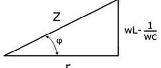
Vector diagram of a real coil and its total resistance
The phase mismatch of the terms in expression (13.12) makes it difficult to determine the amplitude and effective value of the voltage U applied to the circuit. Therefore, we will use the vector method of adding sinusoidal quantities. Amplitudes of the total voltage components
UmR = RIm; UmL = ωLIm,
and the effective quantities
UR = RI; UL = XLI.
Total voltage vector
U = UR + UL
In order to find the magnitude of the vector U , let's construct a vector diagram (Fig. 13.10, a), having previously selected the scales of the current Mi and voltage Mu.
the current vector I as the initial vector of the diagram . The direction of this vector coincides with the positive direction of the axis from which the phase angles are measured (initial phase of the given current Ψi =0). As before, it is convenient (but not necessary) to direct this axis horizontally.
Vector UR coincides in direction with current vector I , and vector UL is directed perpendicular to vector I with a positive angle.
The diagram shows that the current vector I of the total voltage U reflects the current vector I at an angle φ >0, but φ <90°, and is equal in magnitude to the hypotenuse of a right triangle, the legs of which are the vectors of voltage drops in the active and inductive resistances UR and UL :
UR = Ucosφ
The projection of the voltage vector U onto the direction of the current vector is called the active component of the voltage vector and is designated Ua. For a coil according to the diagram in Fig. 13.9 at Ua = UR
U = Usinφ (13.14)
The projection of the voltage vector U onto the direction perpendicular to the current vector is called the reactive component of the voltage vector and is denoted Up . For coil Up = UL
At current i = Imsinωt the voltage equation can be written based on the vector diagram in the form
U = Umsin(ωt+φ)
of the voltage triangle, expressed in units of voltage, by the current I. We obtain a similar triangle of resistance (Fig. 13.10, b), the legs of which are active R = UR/I and inductive XL = UL/I , resistance, and the hypotenuse is the value Z = U/I .
The ratio of the effective voltage to the effective current of a given circuit is called the total resistance of the circuit. The sides of the resistance triangle cannot be considered vectors, since resistances are not functions of time. From the triangle of resistance it follows
The concept of circuit impedance Z allows us to express the relationship between the effective values of voltage and current with a formula similar to Ohm’s formula:
From the triangles of resistance and voltage are determined
cosφ = UR/U = R/Z; sinφ = UL/U = XL/Z; tgφ = UL/UR = XL/R. (13.18)
Graph of current and self-induction EMF versus time
Graphically, the nature of the change in current in the circuit and self-induction EMF over time looks like this:
Dependence of current and self-inductive emf in a coil in an alternating current circuit
The graph shows that the self-induction EMF is greater, the higher the rate of change of current. At the beginning of the period (the area near point 1 on the graph), the current strength increases quickly, and therefore the self-induction emf is maximum here. By the end of the first quarter of the period (point 2), the rate of change decreases almost to zero (the sine wave assumes a horizontal position), after which the current strength decreases more and more rapidly (the section between point 2 and point 3).
Accordingly, the self-induction EMF decreases in point 2 to zero, and then increases again, but at the same time changes its sign to the opposite: now it counteracts the drop in current strength, that is, the current and the EMF coincide in sign. In the next half-cycle the picture repeats.
Coil device
Closer to the idealized element - inductance - is a real element of an electronic circuit - an inductive coil. Unlike inductance, the inductive coil also stores the energy of the electronic field and converts electronic energy into other types of energy, namely thermal. Quantitatively, the ability of the real and idealized parts of an electronic circuit to store magnetic field energy is characterized by a parameter called inductance.
Thus, the term “inductance” is used as the name of an idealized element of an electronic circuit, as the name of a parameter that quantitatively characterizes the characteristics of this element, and as the name of the main parameter of an inductive coil.
The relationship between voltage and current in an inductive coil is determined by the law of electrical induction, from which it follows that when the magnetic flux passing through the inductive coil changes, an electromotive force e is induced in it, proportional to the speed of the coil flux linkage configuration ψ and directed in such a way that the current caused by it tends to prevent magnetic flux from changing:
e = - dψ / dt
In SI units, magnetic flux and flux linkage are expressed in Webers (Wb).
Interesting read: instructions on how to ring a transistor.
The magnetic flux F, penetrating any of the turns of the coil, in the general case can contain two components: the magnetic flux of self-induction Fsi and the magnetic flux of external fields Fvp: F - Fsi + Fvp.
The first component is the magnetic flux caused by the current flowing through the coil, the second is determined by magnetic fields, the existence of which is not related to the coil current - the Earth’s magnetic field, the magnetic fields of other coils and permanent magnets. If the 2nd component of the magnetic flux is caused by the magnetic field of another coil, then it is called mutual induction magnetic flux.
The flux linkage of the coil ψ, as well as the magnetic flux Ф, can be represented as the sum of two components: the flux linkage of self-induction ψsi, and the flux linkage of external fields ψvp
ψ= ψsi + ψvp
The EMF e induced in the inductive coil, in turn, can be represented as the sum of the self-induction EMF, which is caused by the configuration of the magnetic flux of self-induction, and the EMF caused by the configuration of the magnetic flux of the fields external to the coil:
e = esi + evp,
here esi is the EMF of self-induction, evp is the EMF of external fields.
If the magnetic fluxes of the fields external to the inductive coil are equal to zero and only the self-induction flux penetrates the coil, then only the self-induction emf is induced in the coil.
Phase shift between voltage and current
This phenomenon is due to the inductor's resistance to changes in current.
A simple experiment will help you study the phenomenon, for which you will need the following devices and elements:
- DC source;
- oscilloscope;
- frequency generator;
- 100 Ohm resistor;
- inductor.
All elements are connected in series to a DC source. The oscilloscope shows two sinusoids displaying the voltage at the frequency generator (red) and at the resistor (yellow).
The second sinusoid can be considered a display of current fluctuations across the resistor, since it always corresponds in amplitude, phase and frequency to the voltage in a given area.
Progress of the experiment:
- the generator is tuned to a frequency of 1 kHz. The oscilloscope shows that the phases of both sinusoids coincide. The amplitude on the second sine wave is almost 2 V;
- increase the current frequency to 100 kHz. The oscilloscope reflects two changes: the amplitude of voltage fluctuations across the resistor has decreased, and the resistor sine wave has shifted relative to the generator sine wave: this is a phase shift;
- with a further increase in frequency, the following is observed: the voltage amplitude across the resistor drops to 480 mV, and the phase shift increases;
- when setting the maximum possible frequency, the voltage amplitude across the resistor drops to 120 mV. The phase shift approaches 900 (a quarter of a period).
Experience has confirmed that the inductive reactance of the coil increases with increasing frequency. At the same time, a phase shift is observed between the source voltage and load current, tending to 900.