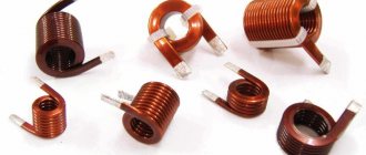
Hello, dear readers of the site. Inductor is one of the elements without which it will not be possible to build a receiver, TV, radio-controlled model, transmitter, signal generator, modem converter, surge protector, etc.
An inductor or simply a coil can be thought of as several turns of wire wound in a spiral. The current passing through each turn of the spiral creates a magnetic field in them, which, intersecting with neighboring turns, induces self-induction emf in them. And the longer the wire and the greater the number of turns it forms, the greater the self-induction.
Inductance
At its core, inductance is electrical inertia.
and its main property is to
resist any change in the flowing current
.
If a certain current is passed through the coil, its inductance will counteract
both the decrease and the increase in the current flowing.
Unlike a capacitor, which allows alternating current to pass but not direct current, an inductor allows direct current to pass freely and resists alternating current because it changes faster than the magnetic field can change.
And the greater the inductance of the coil and the higher the frequency of the current, the stronger the resistance. This property of the coil is used, for example, in receiving equipment, when it is necessary to block the path of alternating current in an electrical circuit.
Inductance is measured in henry
(H),
millihenry
(1 mH = 10ˉ3 Hn),
microhenry
(1 μH = 10ˉ6 Hn),
nanohenry (
1nHn = 10ˉ9 Hn) and is designated by the Latin letter
L.
Magnetic field of the coil
If current flows through the coil, a magnetic field appears around it. It can be seen by conducting an experiment with iron filings, similar to what we did for a straight conductor with current in the last lesson.
Figure 3 shows a schematic representation of magnetic lines for a current-carrying coil.
Figure 3. Magnetic lines of a coil with current
As you can see, magnetic lines are closed curves . It is generally accepted that they are directed from the north pole of the coil to the south .
General properties of inductors
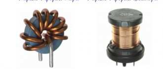
Depending on the required inductance and the frequency at which the coil will operate, it can have a variety of designs.
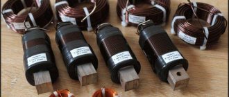
For high frequencies, this can be a simple coil consisting of several turns of wire or a coil with a core made of ferromagnetic material and have an inductance from several nanohenries to several tens of millihenries. Such coils are used in radio receiving, transmitting, measuring equipment, etc.
Coils operating at high frequencies can be divided into circuit coils
,
coupling coils
and
high frequency chokes
.
In turn, the coils of the circuits can be with constant inductance
and
variable inductance
(variometers).
By design, high-frequency coils are divided into single-layer and multilayer, shielded and unshielded, coils without cores and coils with magnetic and non-magnetic cores, frameless, cylindrical flat and printed.
To operate in low-frequency alternating current circuits, at audio frequencies, in input filters of power supplies, and in power circuits of lighting electrical equipment, coils with a sufficiently high inductance are used. Their inductance reaches tens and even hundreds of henries, and large voltages can be created in the windings and significant currents can flow.
To increase the inductance in the manufacture of such coils, magnetic circuits (cores) are used, assembled from individual thin insulated plates made of special magnetic materials - electrical steels, permalloys, etc.
The use of stacked magnetic cores is due to the fact that under the influence of an alternating magnetic field, eddy currents are formed in a solid magnetic core, which can be considered as many short-circuited turns, which heat the magnetic core, uselessly consuming part of the magnetic field energy. The insulation between the layers of steel is in the path of eddy currents and significantly reduces losses.
Coils with magnetic cores made of insulated plates can be divided into chokes
and
transformers
.
Basic parameters of inductors
The properties of coils can be characterized by four main parameters: inductance
,
quality factor
,
intrinsic capacity
and
stability
.
Inductance.
Inductance
(
self-induction coefficient
) is the main electrical parameter and characterizes the amount of energy stored by the coil when electric current flows through it. The greater the inductance of the coil, the more energy it stores in its magnetic field.
Inductance depends on the size of the frame, shape, number of turns of the coil, diameter and grade of wire, as well as on the shape and material of the magnetic circuit (core).
In amateur radio circuits, as a rule, the inductance value is not indicated, since the radio amateur is not interested in this value, but in the number of turns of wire in the coil, the diameter and grade of the wire, the method of winding (in bulk, turn to turn, cross to cross, sectional winding) and dimensions coil frame.
Good quality.
Quality factor
(
Q
) is characterized by the quality of the inductor in AC circuits and is defined as the ratio of the reactance of the coil to its
active loss resistance
.
Active resistance includes the resistance of the coil winding wire; resistance introduced by dielectric losses in the frame; resistance introduced by its own capacitance and resistance introduced losses in screens and cores.
The less
active resistance, the
higher
the quality factor of the coil and its quality. In most cases, the quality factor of the coil is determined by the resonant properties and efficiency. contour. Modern medium-sized coils have a quality factor of about 50 - 300.
Own capacity.
Inductors have their own capacitance
, which increases as the number of turns and coil sizes increase.
Between adjacent turns there is interturn capacitance
, due to which some of the current does not pass through the wire, but through the capacitance between the turns, causing the resistance between the coil terminals to decrease.
The thing is that the total voltage applied to the coil is divided into interturn voltages, due to which an electric field is formed between the turns, causing an accumulation of charges. The turns, separated by layers of insulation, form the plates of many small capacitors through which part of the current flows, from the total capacitance of which the coil’s own capacitance is formed. Thus, the coil has not only inductive but also capacitive properties.
Self-capacitance is a harmful parameter and they strive to reduce it by using special frame shapes and wire winding methods.
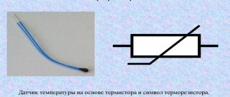
Stability.
Stability
coil is characterized by changes in its parameters under the influence of temperature, humidity and time.
The change in inductance under the influence of temperature is characterized by the temperature coefficient of inductance (TCI), equal to the relative change in inductance with a temperature change of 1°C. The TCI of the coil is determined by the winding method and the quality of the frame dielectric.
Humidity
causes an increase in its own capacitance and dielectric losses, and also reduces the stability of the coil. To protect against moisture, sealing or impregnation and enveloping of the winding with non-hygroscopic compounds is used.
Such coils have a lower quality factor and a large intrinsic capacity, but they are more resistant to moisture.
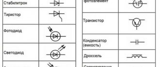
Element labeling
As with all markings, they are marked with letters and colors. The letter markings have several differences.
- Referred to as microhenry.
- Like a set of different letters and numbers. "R" denotes decimal points, and the trailing letters indicate possible tolerance.
The color marking is recognized as the color on the resistors.
These are the main points worth knowing about their functioning and use. If you want to expand your knowledge and get more information about the operation of inductors, we recommend watching several videos from experts.
Inductors with magnetic cores
Magnetic cores are used to produce small-sized coils for various purposes.
(cores), which are made from
magnetodielectrics
and
ferrites
. Coils with magnetic cores have a smaller number of turns for a given inductance, short wire length and small dimensions.
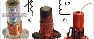
A valuable property of coils with magnetic cores is the ability to adjust them, i.e. changes in inductance within small limits by moving a special cylindrical trimmer inside the coil, consisting of ferrite with a threaded bushing pressed onto it.
Magnetodielectrics
They are a crushed substance containing iron (ferromagnetic), the particles of which are evenly distributed in the mass of the dielectric (bakelite or aminoplast). The most widely used magnetic cores are made of alsifer (an alloy of aluminum, silicon and iron) and carbonyl iron.
Ferrites
They are solid solutions of metal oxides or their salts that have undergone special heat treatment (firing).
The resulting substance - semiconductor ceramics
- has very good magnetic properties and low losses even at very high frequencies.
The main advantage of ferrites is their high magnetic permeability, which makes it possible to significantly reduce the size of the coils.
In old circuit diagrams, magnetic cores made of magnetodielectrics and ferrites were designated the same way - with a thick dashed line
(Fig. a).
Subsequently, the ESKD standard left this symbol for magnetic cores made of magnetodielectric, and for ferrite ones it introduced a designation that was previously used only for magnetic cores of low-frequency chokes and transformers - a solid thick line
(Fig. b).
However, according to the latest edition of GOST 2.723.68 (March 1983), the magnetic circuits of the coils are depicted by lines of normal thickness
(Fig. c).
Coils, the inductance of which can be changed using a magnetic circuit, are indicated on electrical diagrams using a tuning control sign
, which is introduced into its symbol.
A change in inductance is indicated in two ways: either by a tuning control sign crossing the designations of the coil and magnetic circuit (Fig. a), or only by crossing the magnetic circuit with its image above the coil (Fig. b).
Variometers
In the antenna circuits of shortwave transmitters and special VHF receivers, variometers with a variable number of turns are used. Such a variometer consists of a cylindrical or conical frame with a spiral groove in which the coil wire is laid.
A contact roller or spring brush is pressed against the part of the wire protruding above the frame, which, when the coil rotates, slides along the turns and moves in a plane parallel to the generatrix of the cylinder or cone. Thus, it becomes possible to introduce the required number of turns into the circuit, i.e., obtain the required inductance.
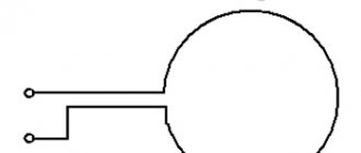
In the symbol of a variometer of a similar design, the roller or brush is depicted in the form of an arrow, the tip of which touches the convex part of the semicircle of the main symbol (Fig. 3).
Rice. 3. Designation of the variometer.
Variometers are characterized by a smooth change in inductance. To change it stepwise, as well as in some other cases, taps are made at the coils. The symbols for coils with taps are shown in Fig. 4.
Rice. 4. Designation of inductors with taps from turns.
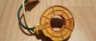
Shielded inductors
To eliminate parasitic connections caused by the external electromagnetic field of the coil and the influence of the surrounding space on the coil, it is shielded, i.e. placed in a closed metal screen
.
However, under the influence of the screen, the main electrical parameters of the coil change: inductance and quality factor decrease, resistance and self-capacitance increase.
The closer the screen is located to its turns, the greater the change in coil parameters, i.e. the change in parameters depends on the relationship between the dimensions of the coil and the dimensions of the screen itself.
For high-frequency coils, screens are made in the form of round or rectangular glasses made of aluminum, copper or brass with a wall thickness of 0.3 - 0.5 mm.
To indicate a shielded coil in the diagrams, its symbol is placed in a shielding sign, which is connected to the housing.
It should also be noted that only large coils with a diameter of more than 15 - 20 mm need to be shielded.
Coils with a diameter of no more than 4 - 5 mm create a magnetic field in a relatively small space and when such coils are removed from other parts at a distance of 4 - 5 times their diameter, as a rule, dangerous connections do not arise, so they do not require special shielding.
Designation of coils with taps and the beginning of the winding
In radio and electrical equipment, for example, in receivers or pulse voltage converters, sometimes not the entire inductance of the coil is used, but only some of it. For such cases, the coils are made with a tap or taps.
When developing certain designs, it is sometimes necessary to strictly observe the beginning and end of the winding of a coil or transformer. To indicate which end of the winding is the beginning and which is the end, a bold dot is placed at the terminal of the beginning of the winding.
To tune coils at frequencies above 15...20 MHz, magnetic cores made of non-magnetic materials (copper, aluminum, etc.) are often used. The eddy currents arising in such a magnetic circuit under the influence of the magnetic field of the coil create their own field, counteracting the main one, as a result of which the inductance of the coil decreases.
A non-magnetic magnetic trimmer is designated in the same way as a ferrite one, but the chemical symbol of the metal from which it is made is indicated next to it. The picture shows a trimmer made of copper.
That's all I wanted to tell you about inductors . Good luck!
Literature: 1. V. A. Volgov “Parts and components of radio-electronic equipment.” 2. V.V. Frolov “The language of radio circuits.” 3. M. A. Sgut “Symbols and radio circuits.”