Types of Electronic Circuits
In radio electronics, there are several types of circuits: circuit diagrams, wiring diagrams, block diagrams, voltage and resistance maps.
Schematic diagrams
Such an electrical diagram gives a complete picture of all the functional components of the circuit, the types of connections between them, and the operating principle of electrical equipment. Circuit diagrams are commonly used in distribution networks. They are divided into two types:
- Single-line. This drawing shows only power circuits.
- Full. If the electrical installation is simple, then all its elements can be displayed on one sheet. To describe equipment that contains several circuits (power, measuring, control), drawings are made for each unit and placed on different sheets.
Block diagrams
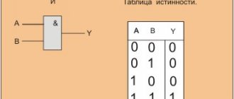
In radio electronics, a block is an independent part of an electronic device. A block is a general concept; it can include both a small and a significant number of parts. A block diagram (or block diagram) gives only a general concept of the structure of an electronic device. It does not display: the exact composition of the blocks, the number of ranges of their functioning, the schemes according to which they are assembled. In a block diagram, blocks are represented by squares or circles, and the connections between them are represented by one or two lines.
The directions of signal passage are indicated by arrows. The names of the blocks in full or abbreviated form can be applied directly to the diagram. The second option is to number the blocks and decipher these numbers in a table located in the margins of the drawing. Graphic images of blocks can display the main parts or plot their operation.
Assembly
Wiring diagrams are convenient for creating an electrical circuit yourself. They indicate the location of each circuit element, communication methods, and the laying of connecting wires. The designation of radioelements on such diagrams usually approaches their natural appearance.
Voltage and resistance map
A voltage map (diagram) is a drawing in which, next to the individual parts and their terminals, the voltage values characteristic of the normal operation of the device are indicated. Voltages are placed in the gaps of the arrows, showing in which places measurements need to be made. The resistance map indicates the resistance values characteristic of a working device and circuits.
Designation of radio components on electrical circuits
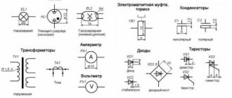
The designation on the diagrams of radio elements appears in the form of graphic figures. For example, a resistor is depicted as an elongated rectangle with the letter “R” and a serial number next to it. “R15” means that the resistor in the circuit is the 15th in a row. The amount of power dissipated by the resistance is immediately prescribed.
Understanding electrical measuring instruments
Particular attention should be paid to the designation on the microcircuits. For example, you can consider the KR155LAZ microcircuit. The first letter "K" means a wide range of applications. If there is an “E”, then this is an export version. The second letter “P” determines the material and type of case. In this case it is plastic. A unit is a type of part, in the example a semiconductor chip. 55 – serial number of the series. The following letters express the AND-NOT logic.
Where to start reading diagrams
You need to start by reading circuit diagrams. For more effective learning, you need to combine the study of theory with practice. You must understand all symbols on the board. There is a lot of information on the Internet for this. It is a good idea to have reference material on hand in book format. In parallel with mastering the theory, you need to learn how to solder simple circuits.
How are radioelements connected in a circuit?
Boards are used to connect radio components. To make contact tracks, a special solution is used to etch copper foil on the dielectric layer of the printed circuit board. Excess foil is removed, leaving only the necessary tracks. The leads of the parts are soldered to their edges.
Additional Information. Lithium batteries, when heated by a soldering iron, can swell and collapse. To prevent this from happening, spot welding is used.
Letter designation of radioelements in the circuit
To decipher the letter designations of parts in the diagram, you need to use special tables approved by GOST. The first letter means the device, the second and third letters specify the specific type of radio component. For example, F stands for arrester or fuse. The full letters FV let you know that this is a fuse.
Graphic designation of radioelements in the circuit
The graphics of the circuits include a conventional two-dimensional designation of radioelements accepted throughout the world. For example, a resistor is a rectangle, a transistor is a circle in which the lines show the direction of the current, a choke is a stretched spring, etc.
A novice radio amateur should have a table of images of radio components at hand. Below are examples of tables of graphic symbols for radio components.
Table of graphic designations of radioelements on the diagram
table 2
Table 3
Table 4
For beginning radio amateurs, it is important to stock up on reference literature where you can find information about the purpose of a particular radio component and its characteristics. You can learn how to make your own printed circuit boards and how to solder circuits correctly using video lessons online.
Where to start reading diagrams?
In order to learn how to read circuits, first of all, we must study what a particular radio element looks like in a circuit. In principle, there is nothing complicated about this. The whole point is that if the Russian alphabet has 33 letters, then in order to learn the symbols of radio elements, you will have to try hard.
Until now, the whole world cannot agree on how to designate this or that radio element or device. Therefore, keep this in mind when you collect bourgeois schemes. In our article we will consider our Russian GOST version of the designation of radioelements
How are radioelements connected in a circuit?
So, it seems that we have decided on the task of this scheme. Straight lines are wires or printed conductors through which electric current will flow. Their task is to connect radioelements.
The point where three or more conductors connect is called a node. We can say that this is where the wiring is soldered:
If you look closely at the diagram, you can see the intersection of two conductors
Such intersection will often appear in diagrams. Remember once and for all: in this place the wires are not connected and they must be insulated from each other. In modern circuits, you can most often see this option, which already visually shows that there is no connection between them:
Here, it is as if one wire goes around the other from above, and they do not contact each other in any way.
If there was a connection between them, then we would see this picture:
Reading an Electrical Diagram
The diagram itself, on which the symbols are drawn, is called a schematic diagram. It not only shows how certain elements of the circuit are connected, but also explains how the entire device works, showing the principle of its operation. To achieve this result, it is important to correctly show the individual groups of elements and the connection between them.
In addition to the fundamental one, there are also installation ones. They are designed to accurately display each element in relation to each other. The arsenal of radioelements is huge. New ones are constantly being added. Nevertheless, the UGO in all diagrams is almost the same, but the letter code is significantly different. There are 2 types of standard:
- state, this standard may include several states;
- international, used almost all over the world.
But whatever standard is used, it must clearly show the designation of radio components on the diagram and their name. Depending on the functionality, UGO radio components can be simple or complex. For example, several conditional groups can be distinguished:
- power supplies;
- indicators, sensors;
- switches;
- semiconductor elements.
This list is incomplete and serves for illustrative purposes only. To make it easier to understand the symbols of radio components in the diagram, you need to know the principle of operation of these elements.
Conditions for designating radio components
A correct electrical diagram can not only tell you how to connect its elements, but also explain the principle of operation to a knowledgeable person. Graphic symbols in circuit design are accepted by global standards, so they are the same almost everywhere. But the letter code of an element may differ greatly from the state one. Therefore, the following is important for any electrical circuit:
- certain type;
- characteristic audience;
- creation path (manually or on a printing press);
- operating conditions of electrical equipment;
- availability of installation repairs.
Confusing electrical circuit
This article does not talk about how to correctly identify radio components by appearance alone. We will talk about circuit design and symbols of resistors, transistors, etc.
Domestic marking of microcircuits
Typical markings of domestic microcircuits are as follows: KR580VG80A.
The first letter indicates the specifics of the microcircuit:
K – orientation to the mass market; E – export version.
If the first letter is missing, the chip is highly specialized and configured for special tasks.
The second letter in the microcircuit marking indicates the type of case:
A – plastic (compact); B – absent (unpackaged microcircuit); E – DIP (metal); M – metal ceramics; N – metal ceramics (compact); P – DIP (plastic).
The number following the housing type characterizes whether the microcircuit belongs to one or another design and technical group.
1, 4, 8 – hybrid chips; 1, 5, 6, 7 – semiconductor chips; 3 – film version.
The next two digits indicate the series number.
The letters following the series indicate the functional purpose of the microcircuit.
A – shapers; B – delay modules; BM – passive electronic component; BR – active electronic component; B – computing module; G – pulse generator; EP – power source; I – digital electronic components; K – switching modules; H – bundles of components; P – various types of converters; P – storage modules; U – amplifiers; F – filters; X – multifunctional microcircuits.
The serial number of the series is followed by the development number (two-digit or single-digit).
The last symbol in the microcircuit marking indicates any features in its electrical characteristics.
Foreign marking of microcircuits (using the Pro Electron system)
In Europe and the West, there are several established labeling schemes for electronic components, each of which has minor differences in its field of application. But the basic principles remain common to all, and they are all listed in the classification adopted by the international Pro Electron association.
According to the Pro Electron classification, the marking of microcircuits consists of three alphabetic symbols followed by a numerical value.
The first letter indicates the method of signal conversion in the circuit:
T – analog conversion; S – digital conversion; U – mixed type transformation.
The second letter after the type of signal conversion does not have any fixed meaning (it is selected by the manufacturer). The exception is the letter “H”, which always denotes the hybrid operating principle of the chip.
In the case of digital electronic components, the first two letters indicate the features of the device:
FY – ESL line; GA – low-current TTL chips; GF – standard TTL; GJ – productive TTL; H – complementary microcircuits.
The third symbol in the microcircuit marking indicates the range of its operating temperatures:
A) not nominated; B) from 0 to +70 °C; C) from -55 to +125 °C; D) from -25 to +70 °C; E) from -25 to +85 °C; F) from -40 to +85 °C; G) from -55 to + 85 °C.
After the letter indicating the temperature range, there is a four-digit number - this is the serial number of the chip.
Following the serial number, the type of case is indicated in the microcircuit marking. This designation can be two-letter or one-letter.
The meaning of the first letter in two-letter markings:
C – cylindrical body; D – DIP housing (contacts are located in two rows along the edges of the microcircuit); E – DIP housing with heat dissipator; F – quadrangular flat (double-sided placement of contacts); G – quadrangular flat (four-sided placement of contacts); K – TO-3 body; M – multi-row body; Q – symmetrical arrangement of contacts along four edges; R – housing with a four-row arrangement of contacts and an external heat dissipator; S – contacts are placed in one row; T – housing with three-row arrangement of contacts.
We recommend reading: Flashlight from a cash register power supply
The meaning of the second letter in two-letter markings:
G – glass ceramics; M – metal; P – plastic; X – other materials.
If the serial number in the microcircuit marking is followed by one letter, it should be interpreted as follows:
C – cylindrical body; D – ceramic body; F – flat body; P – DIP plastic housing; Q – four-row arrangement of contacts; T – miniature plastic case; U – unpackaged integrated circuit.
The next two digits after the housing type are the serial number of the electronic component. The last number in the microcircuit marking is its operating temperature range. It should be interpreted as follows:
0) not nominated; 1) from 0 to +70 °C; 2) from -55 to +125 °C; 3) from -10 to +85 °C; 4) from +15 to +55 °C; 5) from -25 to +70 °C; 6) from -40 to + 85 °C.
We hope this information will help you understand the variety of markings, and you can easily select and buy microcircuits with the desired characteristics.
Types of electrical circuits
Since electronics is a fairly broad concept, it is reasonable to assume that it combines many concepts, each of which has certain characteristics and needs for schematic notation. Therefore, there are a large number of different electrical circuits that bear little resemblance to each other, but mean the same thing.
Types of electrical circuits
Circuits are divided into several types, among them there are electrical ones, they are divided into 8 types, each of which has its own designation - a number from 0 to 7. We will talk about the types that are more familiar to the common person, which do not have a professional orientation and are intended directly for amateur radio technicians, etc.
Schematic diagrams
Directly applied in distribution networks, since they often require a clear understanding of the principles of operation and interconnection of electrical equipment. Such diagrams always indicate functional circuit units, connections between components and radio components using conventional graphic symbols.
Single line circuit diagram
Note! Such circuits have 2 varieties (single-line or full), regardless of which they contain radio components with individual numbers, factory names and electrical quantities (resistance, consumed voltage, cross-sectional area, etc.).
The first type is a drawing with information about the primary networks of electrical equipment, which are also called power.
Complete circuit diagram
The second, despite its name, may contain a complete circuit of secondary networks, or a separate element of an electrical circuit, or electrical components of one product. This is determined depending on the further purpose and use of the product. It can be complexly arranged or huge, resulting in the need to split the entire drawing into several parts, and that’s when clippings come to the rescue, where you can find more detailed information. These diagrams may indicate the condition of electrical equipment or contacts.
You may be interested in this: Learning to read electrical diagrams
Block diagrams
This type, also called a block diagram, exists not only in electronics, but also in programming and algorithmization, and their essence is the same - to give a general concept of the structure and operation of a particular object.
From the name it is obvious that these circuits in electronics contain an image of an electrical circuit block. A block is a fairly broad concept in electrical engineering, but it is generally denoted as follows: an independent collection of an indefinite number of parts of an electrical circuit with one common specific function.
Block diagram
Block diagrams allow you to see the overall picture and quickly move on to further connections and repairs. There will not be any special symbols on them, since the blocks are usually in the form of circles or squares with names or abbreviations inside. There are also arrows that can be used to set the correct order for reading the diagram.
Important! These circuits can be understood even by a person without special knowledge of electrical engineering.
Assembly
This type of diagram indicates the location of all elements of the electrical circuit, methods of their connection and connection points on top of the building diagram. Most often, such circuits are used to install electrical wiring in rooms, which is where their name comes from.
Wiring diagram
As can be seen from the figure, these diagrams have their own symbols, which are indicated in the drawing and are often close to the actual appearance of certain elements.
For your information! These diagrams indicate all the connecting wires and their methods of communication. It is also important to respect the scale and link electrical equipment, in particular, sockets, lighting fixtures, etc. to specific rooms. Therefore, these electrical diagrams are applicable during repairs and operation of premises.
Letter abbreviations for radio electronics
| Letter abbreviation | Decoding the abbreviation |
| A.M. | amplitude modulation |
| AFC | automatic frequency adjustment |
| APCG | automatic local oscillator frequency adjustment |
| APChF | automatic frequency and phase adjustment |
| AGC | automatic gain control |
| ARYA | automatic brightness adjustment |
| AC | acoustic system |
| AFU | antenna-feeder device |
| ADC | analog-to-digital converter |
| frequency response | amplitude-frequency response |
| BGIMS | large hybrid integrated circuit |
| NOS | wireless remote control |
| BIS | large integrated circuit |
| BOS | signal processing unit |
| BP | power unit |
| BR | scanner |
| DBK | radio channel block |
| BS | information block |
| BTK | blocking transformer personnel |
| BTS | blocking transformer line |
| BOO | Control block |
| BC | chroma block |
| BCI | integrated color block (using microcircuits) |
| VD | video detector |
| VIM | time-pulse modulation |
| VU | video amplifier; input (output) device |
| HF | high frequency |
| G | heterodyne |
| GW | playback head |
| GHF | high frequency generator |
| GHF | hyper high frequency |
| GZ | start generator; recording head |
| GIR | heterodyne resonance indicator |
| GIS | hybrid integrated circuit |
| GKR | frame generator |
| GKCH | sweep generator |
| GMW | meter wave generator |
| GPA | smooth range generator |
| GO | envelope generator |
| HS | signal generator |
| GSR | line scan generator |
| gss | standard signal generator |
| yy | clock generator |
| GU | universal head |
| VCO | voltage controlled generator |
| D | detector |
| dv | long waves |
| dd | fractional detector |
| days | voltage divider |
| dm | power divider |
| DMV | decimeter waves |
| DU | remote control |
| DShPF | dynamic noise reduction filter |
| EASC | unified automated communication network |
| ESKD | unified system of design documentation |
| zg | audio frequency generator; master oscillator |
| zs | slowing system; sound signal; pickup |
| AF | audio frequency |
| AND | integrator |
| ICM | pulse code modulation |
| ICU | quasi-peak level meter |
| ims | integrated circuit |
| ini | linear distortion meter |
| inch | infra-low frequency |
| and he | reference voltage source |
| SP | power supply |
| ichh | frequency response meter |
| To | switch |
| KBV | traveling wave coefficient |
| HF | short waves |
| kWh | extremely high frequency |
| KZV | recording-playback channel |
| CMM | pulse code modulation |
| kk | frame deflection coils |
| km | coding matrix |
| cnc | extremely low frequency |
| efficiency | efficiency |
| KS | deflection system line coils |
| ksv | standing wave ratio |
| ksvn | voltage standing wave ratio |
| CT | check Point |
| KF | focusing coil |
| TWT | traveling wave lamp |
| lz | delay line |
| fishing | back wave lamp |
| LPD | avalanche diode |
| lppt | tube-semiconductor TV |
| m | modulator |
| M.A. | magnetic antenna |
| M.B. | meter waves |
| TIR | metal-insulator-semiconductor structure |
| MOP | metal-oxide-semiconductor structure |
| ms | chip |
| MU | microphone amplifier |
| neither | nonlinear distortion |
| LF | low frequency |
| ABOUT | common base (switching on a transistor according to a circuit with a common base) |
| VHF | very high frequency |
| oi | common source (turning on the transistor *according to a circuit with a common source) |
| OK | common collector (switching on a transistor according to a circuit with a common collector) |
| onch | very low frequency |
| oos | negative feedback |
| OS | deflection system |
| OU | operational amplifier |
| OE | common emitter (connecting a transistor according to a circuit with a common emitter) |
| Surfactant | surface acoustic waves |
| pds | two-speech set-top box |
| Remote control | remote control |
| pcn | code-voltage converter |
| pnc | voltage-to-code converter |
| PNC | converter voltage frequency |
| village | positive feedback |
| PPU | noise suppressor |
| pch | intermediate frequency; frequency converter |
| ptk | tv channel switch |
| PTS | full TV signal |
| Vocational school | industrial television installation |
| PU | preliminary effort |
| PUV | playback pre-amplifier |
| PUZ | recording pre-amplifier |
| PF | bandpass filter; piezo filter |
| ph | transfer characteristic |
| pcts | full color television signal |
| Radar | line linearity regulator; radar station |
| RP | memory register |
| RPCHG | manual adjustment of local oscillator frequency |
| RRS | line size control |
| PC | shift register; mixing regulator |
| RF | notch or stop filter |
| REA | radio-electronic equipment |
| SBDU | wireless remote control system |
| VLSI | ultra-large scale integrated circuit |
| NE | medium waves |
| SVP | touch program selection |
| Microwave | ultra high frequency |
| sg | signal generator |
| SDV | ultralong waves |
| SDU | dynamic light installation; remote control system |
| SK | channel selector |
| SLE | all-wave channel selector |
| sk-d | UHF channel selector |
| SK-M | meter wave channel selector |
| CM | mixer |
| ench | ultra-low frequency |
| JV | grid field signal |
| ss | clock signal |
| ssi | horizontal clock pulse |
| SU | selector amplifier |
| sch | average frequency |
| TV | tropospheric radio waves; TV |
| TVS | line output transformer |
| tvz | audio output channel transformer |
| tvk | output frame transformer |
| TIT | television test chart |
| TKE | temperature coefficient of capacitance |
| tka | temperature coefficient of inductance |
| tkmp | temperature coefficient of initial magnetic permeability |
| tkns | temperature coefficient of stabilization voltage |
| tks | temperature coefficient of resistance |
| ts | network transformer |
| shopping center | television center |
| tsp | color bar table |
| THAT | technical specifications |
| U | amplifier |
| UV | playback amplifier |
| UVS | video amplifier |
| UVH | sample-hold device |
| UHF | high frequency signal amplifier |
| UHF | UHF |
| UZ | recording amplifier |
| Ultrasound | audio amplifier |
| VHF | ultrashort waves |
| ULPT | unified tube-semiconductor TV |
| ULLTST | unified lamp-semiconductor color TV |
| ULT | unified tube TV |
| UMZCH | audio power amplifier |
| CNT | unified TV |
| ULF | low frequency signal amplifier |
| UNU | voltage controlled amplifier. |
| UPT | DC amplifier; unified semiconductor TV |
| HRC | intermediate frequency signal amplifier |
| UPCHZ | intermediate frequency signal amplifier? |
| UPCH | intermediate frequency image amplifier |
| URCH | radio frequency signal amplifier |
| US | interface device; comparison device |
| USHF | microwave signal amplifier |
| USS | horizontal sync amplifier |
| USU | universal touch device |
| UU | control device (node) |
| UE | accelerating (control) electrode |
| UEIT | universal electronic test chart |
| PLL | phase automatic frequency control |
| HPF | high pass filter |
| FD | phase detector; photodiode |
| FIM | pulse phase modulation |
| FM | phase modulation |
| LPF | low pass filter |
| FPF | intermediate frequency filter |
| FPCHZ | audio intermediate frequency filter |
| FPCH | image intermediate frequency filter |
| FSI | lumped selectivity filter |
| FSS | concentrated selection filter |
| FT | phototransistor |
| FCHH | phase-frequency response |
| DAC | digital-to-analog converter |
| Digital computer | digital computer |
| CMU | color and music installation |
| DH | central television |
| BH | frequency detector |
| CHIM | pulse frequency modulation |
| world championship | frequency modulation |
| shim | pulse width modulation |
| shs | noise signal |
| ev | electron-volt (e•V) |
| COMPUTER. | electronic computer |
| emf | electromotive force |
| ek | electronic switch |
| CRT | cathode-ray tube |
| AMY | electronic musical instrument |
| emos | electromechanical feedback |
| EMF | electromechanical filter |
| EPU | record player |
| Digital computer | electronic digital computer |
How to read diagrams of radio-electronic devices, designations of radio components
Knowing the general appearance of radio components, you can, of course, to some extent understand the structure of the radio-electronic device, but still the radio amateur will have to draw on paper the contours of the parts and the connection between them.
Back in the last century, in order to preserve the design and circuit solutions of radio devices, the pioneers of radio engineering made drawings of them. If you look at these drawings, you can see that they were made at a very high artistic level.
This was usually done by the inventors themselves, if they had the ability, or by invited artists. Drawings of structures and connections of parts were made from life.
In order not to spend a lot of money on drawing radio devices and to make the work of designers easier, they began to make drawings with simplifications. This made it possible to repeat the design much faster in another city or country and preserve the circuit solutions for posterity. The first drawn diagrams appeared at the beginning of the 19th century.
A lot of time and sometimes money could be spent on drawing an approximate view of a part; in those days it was not yet possible to use computers and programs for drawing diagrams.
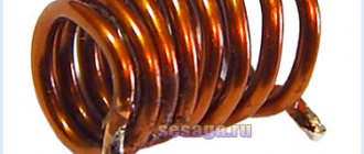
The details were drawn in detail. For example, in 1905, an inductor coil was depicted in isometry, that is, in three-dimensional space, with all the details, frame, winding, number of turns (Fig. 1). In the end, images of parts and their connections began to be made conditionally, symbolically, but at the same time preserving their features.
Rice. 1. Evolution of the conventional graphic image of an inductor on electrical circuits
In 1915, the drawing of the circuits was simplified; the frame was no longer depicted; instead, lines of different thicknesses were used to emphasize the cylindrical shape of the coil.
After 40 years, the coil was already depicted with lines of the same thickness, but still preserving the original features of its appearance. Only in the early 70s of our century did the coil begin to be depicted as flat, that is, two-dimensional, and radio-electronic circuits began to take on their current form.
Drawing complex electronic circuits is very labor-intensive work. To carry it out, an experienced draftsman-designer is required.
In order to simplify the process of drawing diagrams, the American inventor Cecil Effinger designed a typewriter in the late 60s of the 20th century.
In the machine, instead of the usual letters, symbols for resistors, capacitors, diodes, etc. were inserted. The work of making radio circuits on such a machine became accessible to even a simple typist. With the advent of personal computers, the process of making radio circuits has been greatly simplified.
Now, knowing a graphic editor, you can draw an electronic circuit on a computer screen and then print it on a printer. Due to the expansion of international contacts, the symbols of radio circuits have been improved and now they are not very different from each other in different countries. This makes radio circuits understandable to radio professionals around the world.
The third technical committee of the International Electrotechnical Commission (IEC) deals with the graphic symbols and rules for the execution of electrical circuits.
In radio electronics, three types of circuits are used: block diagrams, circuit diagrams and wiring diagrams. In addition, to check electronic equipment, voltage and resistance maps are drawn up.
Block diagrams do not reveal the specifics of any parts, nor the number of ranges, nor the number of transistors, nor by what scheme these or other nodes are assembled; it only gives a general idea of the composition of the equipment and the interconnection of its individual nodes and blocks. The schematic diagram shows the symbols of the elements of the device or blocks and their electrical connections.
The circuit diagram does not give an idea of the appearance, or the location of parts on the board, or how to arrange the connecting wires. This can only be found out from the wiring diagram.
It should be noted that on the wiring diagram the parts are depicted in such a way that their appearance resembles their real outlines. To check the operating modes of electronic equipment, special voltage and resistance maps are used. These maps indicate voltage and resistance values relative to the chassis or ground wire.
In our country, when drawing radio-electronic circuits, we are guided by the state standard, abbreviated as GOST, which indicates how certain radio components should be conventionally depicted.
To make it easier to remember the symbols of individual elements of electronic equipment, their images contain characteristic features of the parts. On the diagrams, an alphanumeric designation is placed next to the conventional graphic image.
The designation consists of one or two letters of the Latin alphabet and numbers indicating the serial number of this part in the diagram. The serial numbers of graphic images of radio components are placed based on the sequence of arrangement of similar symbols, for example, in the direction from left to right or from top to bottom.
Latin letters indicate the type of part:
- C - capacitor,
- R - resistor,
- VD - diode,
- L - inductor,
- VT - transistor,
- etc.
Next to the alphanumeric designation of the part, the value of its main parameter (capacitance of the capacitor, resistor resistance, inductance, etc.) and some additional information are indicated.
The most commonly used conventional graphic images of radio components on circuit diagrams are given in Table. 1, and their letter designations (codes) are given in table. 2.
At the end of the positional designation a letter may be placed indicating its functional purpose, table. 3. For example, R1F is a protective resistor, SB1R is a reset button.
To increase the information richness of a printed publication, in the scientific and technical literature on radio electronics, as well as in various diagrams related to this field of knowledge, conventional letter abbreviations for devices and the physical processes occurring in them are used. In table 4 shows the most commonly used abbreviations and their interpretation.
Table 1. Symbols of radio components on circuit diagrams.
Table 2. Letter designations (codes) of radio components on circuit diagrams.
| Devices and elements | Letter code |
| Devices: amplifiers, remote control devices, lasers, masers; general designation | A |
| Converters of non-electrical quantities into electrical ones (except for generators and power supplies) or vice versa, analog or multi-digit converters, sensors for indicating or measuring; general designation | IN |
| Speaker | VA |
| Magnetostrictive element | BB |
| Ionizing radiation detector | BD |
| Selsyn sensor | Sun |
| Selsyn receiver | BE |
| Telephone (capsule) | B.F. |
| Thermal sensor | VC |
| Photocell | B.L. |
| Microphone | VM |
| Pressure meter | VR |
| Piezo element | IN |
| Speed sensor, tachogenerator | BR |
| Pickup | B.S. |
| Speed sensor | VV |
| Capacitors | WITH |
| Integrated circuits, microassemblies: general designation | D |
| Integrated analog microcircuit | D.A. |
| Integrated digital microcircuit, logical element | DD |
| Information storage device (memory) | D.S. |
| Delay device | D.T. |
| Various elements: general designation | E |
| Lighting lamp | EL |
| A heating element | EC |
| Arresters, fuses, protection devices: general designation | F |
| fuse | F.U. |
| Generators, power supplies, crystal oscillators: general designation | G |
| Battery of galvanic cells, batteries | G.B. |
| Indicating and signaling devices; general designation | N |
| Sound alarm device | ON |
| Symbolic indicator | HG |
| Light signaling device | H.L. |
| Relays, contactors, starters; general designation | TO |
| Devices and elements | letter code |
| Electrothermal relay | kk |
| Time relay | CT |
| Contactor, magnetic starter | km |
| Inductors, chokes; general designation | L |
| Engines, general designation | M |
| Measuring instruments; general designation | R |
| Ammeter (milliammeter, microammeter) | RA |
| Pulse counter | PC |
| Frequency meter | PF |
| Ohmmeter | PR |
| Recording device | PS |
| Action time meter, clock | RT |
| Voltmeter | PV |
| Wattmeter | PW |
| Resistors are constant and variable; general designation | R |
| Thermistor | RK |
| Measuring shunt | R.S. |
| Varistor | RU |
| Switches, disconnectors, short circuits in power circuits (in equipment power supply circuits); general designation | Q |
| Switching devices in control, signaling and measuring circuits; general designation | S |
| Switch or switch | S.A. |
| Push-button switch | S.B. |
| Automatic switch | SF |
| Transformers, autotransformers; general designation | T |
| Electromagnetic stabilizer | T.S. |
| Converters of electrical quantities into electrical ones, communication devices; general designation | And |
| Modulator | ive |
| Demodulator | UR |
| Discriminator | Ul |
| Frequency converter, inverter, frequency generator, rectifier | UZ |
| Semiconductor and electrovacuum devices; general designation | V |
| Diode, zener diode | V.D. |
| Transistor | VT |
| Thyristor | VS |
| Electrovacuum device | VL |
| Devices and elements | Letter code |
| Microwave lines and elements; general designation | W |
| Coupler | WE |
| Koro tkoea we ka tel | W.K. |
| Valve | W.S. |
| Transformer, phase shifter, heterogeneity | W.T. |
| Attenuator | W.U. |
| Antenna | W.A. |
| Contact connections; general designation | X |
| Pin (plug) | XP |
| Socket (socket) | XS |
| Demountable connection | XT |
| High frequency connector | XW |
| Mechanical devices with electromagnetic drive; general designation | Y |
| Electromagnet | YA |
| Electromagnetic brake | YB |
| Electromagnetic clutch | YC |
| Terminal devices, filters; general designation | Z |
| Limiter | ZL |
| Quartz filter | ZQ |
Table 3. Letter codes for the functional purpose of a radio-electronic device or element.
| Functional purpose of the device, element | Letter code |
| Auxiliary | A |
| Counting | WITH |
| Differentiating | D |
| Protective | F |
| Test | G |
| Signal | N |
| Integrating | I |
| Main | M |
| Measuring | N |
| Proportional | R |
| State (start, stop, limit) | Q |
| Return, reset | R |
| Functional purpose of the device, element | letter code |
| Memorizing, recording | S |
| Synchronizing, delaying | T |
| Speed (acceleration, braking) | V |
| Summing | W |
| Multiplication | X |
| Analog | Y |
| Digital | Z |
Table 4. The most common conventional letter abbreviations in radio electronics, used on various circuits in technical and scientific literature.
| Letter abbreviation | Decoding the abbreviation |
| A.M. | amplitude modulation |
| AFC | automatic frequency adjustment |
| APCG | automatic local oscillator frequency adjustment |
| APChF | automatic frequency and phase adjustment |
| AGC | automatic gain control |
| ARYA | automatic brightness adjustment |
| AC | acoustic system |
| AFU | antenna-feeder device |
| ADC | analog-to-digital converter |
| frequency response | amplitude-frequency response |
| BGIMS | large hybrid integrated circuit |
| NOS | wireless remote control |
| BIS | large integrated circuit |
| BOS | signal processing unit |
| BP | power unit |
| BR | scanner |
| DBK | radio channel block |
| BS | information block |
| BTK | blocking transformer personnel |
| Letter abbreviation | Decoding the abbreviation |
| BTS | blocking transformer line |
| BOO | Control block |
| BC | chroma block |
| BCI | integrated color block (using microcircuits) |
| VD | video detector |
| VIM | time-pulse modulation |
| VU | video amplifier; input (output) device |
| HF | high frequency |
| G | heterodyne |
| GW | playback head |
| GHF | high frequency generator |
| GHF | hyper high frequency |
| GZ | start generator; recording head |
| GIR | heterodyne resonance indicator |
| GIS | hybrid integrated circuit |
| GKR | frame generator |
| GKCH | sweep generator |
| GMW | meter wave generator |
| GPA | smooth range generator |
| GO | envelope generator |
| HS | signal generator |
| Reduction | Decoding the abbreviation |
| GSR | line scan generator |
| gss | standard signal generator |
| yy | clock generator |
| GU | universal head |
| VCO | voltage controlled generator |
| D | detector |
| dv | long waves |
| dd | fractional detector |
| days | voltage divider |
| dm | power divider |
| DMV | decimeter waves |
| DU | remote control |
| DShPF | dynamic noise reduction filter |
| EASC | unified automated communication network |
| ESKD | unified system of design documentation |
| zg | audio frequency generator; master oscillator |
| zs | slowing system; sound signal; pickup |
| AF | audio frequency |
| AND | integrator |
| ICM | pulse code modulation |
| ICU | quasi-peak level meter |
| ims | integrated circuit |
| ini | linear distortion meter |
| inch | infra-low frequency |
| and he | reference voltage source |
| SP | power supply |
| ichh | frequency response meter |
| To | switch |
| KBV | traveling wave coefficient |
| HF | short waves |
| kWh | extremely high frequency |
| KZV | recording-playback channel |
| CMM | pulse code modulation |
| Letter abbreviation | Decoding the abbreviation |
| kk | frame deflection coils |
| km | coding matrix |
| cnc | extremely low frequency |
| efficiency | efficiency |
| KS | deflection system line coils |
| ksv | standing wave ratio |
| ksvn | voltage standing wave ratio |
| CT | check Point |
| KF | focusing coil |
| TWT | traveling wave lamp |
| lz | delay line |
| fishing | back wave lamp |
| LPD | avalanche diode |
| lppt | tube-semiconductor TV |
| m | modulator |
| M.A. | magnetic antenna |
| M.B. | meter waves |
| TIR | metal-insulator-semiconductor structure |
| MOP | metal-oxide-semiconductor structure |
| ms | chip |
| MU | microphone amplifier |
| neither | nonlinear distortion |
| LF | low frequency |
| ABOUT | common base (switching on a transistor according to a circuit with a common base) |
| VHF | very high frequency |
| oi | common source (switching on a transistor according to a common source circuit) |
| OK | common collector (switching on a transistor according to a circuit with a common collector) |
| onch | very low frequency |
| oos | negative feedback |
| OS | deflection system |
| OU | operational amplifier |
| OE | common emitter (connecting a transistor according to a circuit with a common emitter) |
| Reduction | Decoding the abbreviation |
| Surfactant | surface acoustic waves |
| pds | two-speech set-top box |
| Remote control | remote control |
| pcn | code-voltage converter |
| pnc | voltage-to-code converter |
| PNC | converter voltage frequency |
| village | positive feedback |
| PPU | noise suppressor |
| pch | intermediate frequency; frequency converter |
| ptk | tv channel switch |
| PTS | full TV signal |
| Vocational school | industrial television installation |
| PU | preamplifier |
| PUV | playback pre-amplifier |
| PUZ | recording pre-amplifier |
| PF | bandpass filter; piezo filter |
| ph | transfer characteristic |
| pcts | full color television signal |
| Radar | line linearity regulator; radar station |
| RP | memory register |
| RPCHG | manual adjustment of local oscillator frequency |
| RRS | line size control |
| PC | shift register; mixing regulator |
| RF | notch or stop filter |
| REA | radio-electronic equipment |
| SBDU | wireless remote control system |
| VLSI | ultra-large scale integrated circuit |
| NE | medium waves |
| SVP | touch program selection |
| Microwave | ultra high frequency |
| sg | signal generator |
| SDV | ultralong waves |
| Reduction | Decoding the abbreviation |
| SDU | dynamic light installation; remote control system |
| SK | channel selector |
| SLE | all-wave channel selector |
| sk-d | UHF channel selector |
| SK-M | meter wave channel selector |
| CM | mixer |
| ench | ultra-low frequency |
| JV | grid field signal |
| ss | clock signal |
| ssi | horizontal clock pulse |
| SU | selector amplifier |
| sch | average frequency |
| TV | tropospheric radio waves; TV |
| TVS | line output transformer |
| tvz | audio output channel transformer |
| tvk | output frame transformer |
| TIT | television test chart |
| TKE | temperature coefficient of capacitance |
| tka | temperature coefficient of inductance |
| tkmp | temperature coefficient of initial magnetic permeability |
| tkns | temperature coefficient of stabilization voltage |
| tks | temperature coefficient of resistance |
| ts | network transformer |
| shopping center | television center |
| tsp | color bar table |
| THAT | technical specifications |
| U | amplifier |
| UV | playback amplifier |
| UVS | video amplifier |
| UVH | sample-hold device |
| UHF | high frequency signal amplifier |
| Letter abbreviation | Decoding the abbreviation |
| UHF | UHF |
| UZ | recording amplifier |
| Ultrasound | audio amplifier |
| VHF | ultrashort waves |
| ULPT | unified tube semiconductor TV |
| ULLTST | unified lamp-semiconductor color TV |
| ULT | unified tube TV |
| UMZCH | audio power amplifier |
| CNT | unified TV |
| ULF | low frequency signal amplifier |
| UNU | voltage controlled amplifier. |
| UPT | DC amplifier; unified semiconductor TV |
| HRC | intermediate frequency signal amplifier |
| UPCHZ | intermediate frequency audio amplifier |
| UPCH | intermediate frequency image amplifier |
| URCH | radio frequency signal amplifier |
| US | interface device; comparison device |
| USHF | microwave signal amplifier |
| USS | horizontal sync amplifier |
| USU | universal touch device |
| UU | control device (node) |
| UE | accelerating (control) electrode |
| UEIT | universal electronic test chart |
| PLL | phase automatic frequency control |
| Letter abbreviation | Decoding the abbreviation |
| HPF | high pass filter |
| FD | phase detector; photodiode |
| FIM | pulse phase modulation |
| FM | phase modulation |
| LPF | low pass filter |
| FPF | intermediate frequency filter |
| FPCHZ | audio intermediate frequency filter |
| FPCH | image intermediate frequency filter |
| FSI | lumped selectivity filter |
| FSS | concentrated selection filter |
| FT | phototransistor |
| FCHH | phase-frequency response |
| DAC | digital-to-analog converter |
| Digital computer | digital computer |
| CMU | color and music installation |
| DH | central television |
| BH | frequency detector |
| CHIM | pulse frequency modulation |
| world championship | frequency modulation |
| shim | pulse width modulation |
| shs | noise signal |
| ev | electron-volt (e•V) |
| COMPUTER. | electronic computer |
| emf | electromotive force |
| ek | electronic switch |
| CRT | cathode-ray tube |
| AMY | electronic musical instrument |
| emos | electromechanical feedback |
| EMF | electromechanical filter |
| EPU | record player |
| Digital computer | electronic digital computer |
Literature: V. M. Pestrikov - Encyclopedia of radio amateurs.
Other items
All radio components are connected to each other by conductors. In the diagram they are depicted as straight lines and drawn strictly horizontally and vertically. If the conductors have an electrical connection when crossing each other, then a dot is placed at this place. In Soviet and American diagrams, to show that the conductors are not connected, a semicircle is placed at the intersection.
To designate variable capacitors, an arrow is used; it crosses out the capacitor diagonally. In trimmers, a T-shaped sign is used instead of an arrow. Varicond - a capacitor that changes capacitance depending on the applied voltage, is drawn like an alternating one, but the arrow is replaced by a short straight line, next to which there is the letter u. The capacitance is shown with a number and a microFarad (microFarad) is placed next to it. If the capacity is smaller, the letter code is omitted.
Another element that no electrical circuit can do without is a resistor. Indicated in the diagram as a rectangle. To show that the resistor is variable, an arrow is drawn on top. It can be connected either to one of the pins, or be a separate pin. For trimmers, a sign in the form of the letter t is used. As a rule, its resistance is indicated next to the resistor.
Symbols in the form of dashes can be used to indicate the power of fixed resistors. A power of 0.05 W is indicated by three oblique, 0.125 W - two oblique, 0.25 W - one oblique, 0.5 W - one longitudinal. High power is shown in Roman numerals. Due to the diversity, it is impossible to describe all the designations of electronic components on the diagram. To identify a particular radio element, use reference books.
Graphic designation of radio components on the diagram and their names
Radio components are found in any electrical appliance, from a TV to an electric kettle. Typically they are enclosed in a housing to reduce the risk of damage. They are designated using graphic symbols, which will be discussed later.
You may be interested in this: How to find out amperage
All radio components are marked with graphic symbols
For your information! Initially, they were all depicted based on the principle of similarity to their natural appearance. Gradually, with the increase in the number of different types of the same components, it became necessary to use symbols on some radio circuits, which were approved and adopted by the International Electrotechnical Commission.
Resistors
A resistor is an element of electrical circuits that has a fixed or variable physical resistance value. It is designed to reduce voltage in areas of the circuit where it is needed, as well as limit the incoming current and absorb electrical energy. Currently, the most common carbon composite resistors are those that consist of a mixture of ceramic powder and carbon bonded with resin. Since carbon is an excellent conductor of electric current, the resistance on the resistor will depend on its amount (the more carbon, the less resistance and vice versa).
Radio engineering resistor
Note! A resistor belongs to the group of passive elements, that is, it is only capable of reducing the voltage in an electrical circuit. The voltage drop is explained by Kirchhoff's second law and Ohm's law.
On the diagrams, the resistor is designated differently, everything will depend on whether it is constant or variable, and in what country the drawing was made. Thus, a constant resistor is most often indicated by a rectangle with two outputs, and by American manufacturers in the form of a zigzag line.
Fixed resistors
They are characterized by the fact that they have constant values of resistance and input power, when exceeded they fail. The letter “R” (resistor), the serial number in the circuit and the resistance value in ohms, kilo-ohms or mega-ohms are written next to them.
Fixed resistors in the diagram
Features of reading circuits
In circuit diagrams, conductors (or tracks) are indicated by lines.
This designates conductors that intersect, but they do not have a common connection and are not electrically connected to each other.
And this is what they look like if there is a connection between them. The black dot is a node in the circuit. A node is a connection of several conductors or parts together. They are electrically connected to each other.
Common point
Beginner radio amateurs often have a question: what is this symbol on the diagram?
This is the common point (GND, ground). Previously, it was called the common wire. This is how a single power wire is designated. Usually this is a minus of nutrition. Previously, in the diagrams they could make the common wire and the power plus. In this case, the diagram without a common point would look like this:
A common point with unipolar power supply looks visually better and more compact than if you simply make a single line between them.
It is also called a common point because any other points on the diagrams can be measured relative to it. For example, place the multimeter probe on a common point, and with the second probe you can check any part of the circuit in the diagram.
Why can it be called ground (GND)? Previously, the chassis of the device body could be used as a common wire. This has caused confusion between grounding and earth. It is interpreted in the context of the schema. The circuit that was discussed above - the common point (ground) is simply a minus of the power supply. Another thing is bipolar current sources and grounding.
Bipolar power supply and common point
In a bipolar supply, the common point is the middle contact between plus and minus.
Grounding
An example of grounding would be a filter in computer power supplies.
From the capacitor filter, noise goes to the power supply housing. This is grounding. And from the power supply they must go into the outlet if you have a ground connection, otherwise the body of the power supply itself may be energized. The currents there are not large, they are not life-threatening. This is done to reduce impulse noise in the power supply and safety.
Sometimes in power supplies, instead of the housing, noise from the capacitor goes to a common point. It all depends on the design and circuitry. In this case, there will be more interference than with grounding.
In general, there are different grounding connections on the diagrams. For example, in digital technology, analog ground is separated from digital ground. so as not to disrupt the operating modes of the circuit. Pulse noise can affect the analog part of the circuit.
DESIGNATIONS OF RADIO COMPONENTS
When manufacturing radio-electronic devices, novice radio amateurs may have difficulty deciphering the symbols on the diagram of various elements. For this purpose, a small collection of the most common symbols of radio components has been compiled. It should be noted that only the foreign version of the designation is given here and differences are possible on domestic diagrams. But since most of the circuits and parts are of imported origin, this is completely justified. The resistor in the diagram is designated by the Latin letter “R”, the number is a conventional serial number according to the diagram. The resistor rectangle can indicate the resistor's power rating—the power it can dissipate over a long period of time without destruction. When current passes through the resistor, a certain power is dissipated, which leads to heating of the latter. Most foreign and modern domestic resistors are marked with colored stripes. Below is a table of color codes.The following is the structure and pinout indicating the purpose of the pins of popular imported digital microcircuits of the CD40xx series and LM operational amplifiers.
The most common designation system for semiconductor radio components is European. The main designation according to this system consists of five characters. Two letters and three numbers - for wide use. Three letters and two numbers - for special equipment. The letter following them indicates different parameters for devices of the same type.
The first letter is the material code:
A - germanium; B - silicon; C—gallium arsenide; R—cadmium sulfide.
The second letter is the purpose:
A - low-power diode; B - varicap; C - low-power low-frequency transistor; D - powerful low-frequency transistor; E - tunnel diode; F - low-power high-frequency transistor; G - several devices in one housing; N—magnetic diode; L - powerful high-frequency transistor; M - Hall sensor; P - photodiode, phototransistor; Q - LED; R - low-power regulating or switching device; S - low-power switching transistor; T - powerful regulating or switching device; U - powerful switching transistor; X - multiplying diode; Y - powerful rectifier diode; Z - zener diode.
Radio components forum
Forum for discussing the material DESIGNATIONS OF RADIO COMPONENTS
FUNCTIONAL GENERATOR
Homemade functional signal generator 0.1 Hz - 100 kHz on the ICL8038 chip.
We are converting a regular tractor toy into a radio-controlled one - photos of the process and the resulting result.
About the use of wireless power technology for various devices.ELECTROLYSER FOR HYDROGEN PRODUCTION
Review of a Chinese device for water electrolysis - photos, videos, description of work.
How to learn to read circuit diagrams
There are really only a few ways. This is theory and practice. If you learn the designation of radio components, this does not mean that you have learned circuit design. It's like learning your ABC's, but without grammar and practice you won't learn the language.
Theory is circuit design, books, a description of the principle of operation of the circuit. Practice involves assembling devices, repairing and soldering.
For example, a simple amplifier circuit with one transistor.
Input X1 plus (left or right channel), X2 minus. The sound signal is sent to electrolytic capacitor C1. It protects transistor VT1 from short circuiting, since transistor VT1 is constantly open using a voltage divider across R1 and R2. The voltage divider sets the operating point at the base of transistor VT1, and the transistor does not distort the input signal. Resistor R3 and capacitor C2, which are connected to the emitter of transistor VT1, perform the function of thermal stabilization of the operating point as the temperature of the transistor increases. Electrolytic capacitor C3 accumulates and filters the supply voltage. The BF1 dynamic head serves as an audio signal output.
Is it possible to understand this only by learning the designations of radio components without circuit design and theory? Unlikely.
The situation is even more complicated with digital technology.
What kind of microcontroller is this, what functions does it perform, what firmware and what fuses are installed in it? And the second microcircuit, what amplifier is it? Without datasheets and a description of the circuit, it will not be possible to understand its operation.
Study circuit design, theory and practice. Simply learning the names of the parts will not help you understand the circuitry. The designation of radio components can be learned on its own with practice and accumulation of knowledge. It all depends on the chosen industry. Signalmen have one circuit design, mobile equipment repairmen have another. And those who deal with sound will not really understand electricians. As well as vice versa. To understand another industry, its circuitry and operating principles, you need to immerse yourself in it.
Circuit diagrams are a kind of language that has different dialects.
Therefore, one should not create illusions. Study circuit design and assemble circuits.
Recommended reading: Logic analyzer
Schematic diagrams help to assemble devices, and when studying the theory, to understand the operation of the device. Without knowledge and experience, a diagram is just a diagram.
Designations of radio components on circuit diagrams
UGO is a conditionally graphic image of a radio component on a diagram. Some UGOs differ from each other.
For example, in the USA the designation of resistors differs from the CIS and Europe.
Because of this, the perception of the scheme changes.
However, in appearance and in designations they are similar. Or, for example, transistors. Somewhere they are drawn with circles, and somewhere without. The size and angle of the arrows may vary. The table shows the UGO of domestic radio components.
UGOName
NPN bipolar transistor PNP bipolar transistor N-base unijunction transistor P-base unijunction transistor Relay winding Grounding Diode Diode bridge Schottky diode Double-node zener diode Bidirectional zener diode Reversing diode Zener diode Tunnel diode Varicap Inductor Inductor with adjustable core Inductor with core Classic transformer Winding Adjustable core Electrolytic capacitor Non-polar capacitor Reference capacitor Variable capacitor Trimmer capacitor On-off switch Reed switch Open switch Close switch N-channel FET FET p-channel Fast-acting fuse Time-lag fuse Fuse Breakdown fuse Thermal coil Refractory fuse Switch-fuse Arrester Arrester two-electrode Electrochemical spark gap Ion spark gap Horn spark gap Symmetrical spark gap Three-electrode spark gap Tubular spark gap Carbon spark gap Vacuum spark gap Valve spark gap Telephone socket Connector Connector Variable resistor Trimmer resistor Resistor 0.125 W resistor 0.25 W resistor 0.5 W resistor 1 W resistor Re resistor 2 W Resistor 5 W Reverse-conducting dinistor Reverse-turn-on dynistor Diode symmetrical thyristor Tetrode thyristor Cathode-controlled thyristor Anode-controlled thyristor Cathode-controlled thyristor Triode symmetrical thyristor Anode-controlled turn-off thyristor Cathode-controlled thyristor Diode optocoupler Photodiode Photothyristor Phototransistor Resistive optocoupler LED Thyristor optocoupler These are not all the details. And there is no particular point in cramming them. Such tables are useful in the form of a reference book. You can identify what kind of part is shown on the diagram while studying it or assembling the device.
Transistors
Most electronic components have only two terminals. However, elements such as transistors are equipped with three terminals. Their designs come in a variety of types, shapes and sizes. Their general principles of operation are the same, and minor differences are associated with the technical characteristics of a particular element.
Transistors are used primarily as electronic switches to turn various devices on and off. The main convenience of such devices is the ability to switch high voltages using a low voltage source.
At its core, each transistor is a semiconductor device with the help of which electrical oscillations are generated, amplified and converted. The most widespread are bipolar transistors with the same electrical conductivity of the emitter and collector.
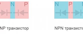
In the diagrams they are designated by the letter code VT. The graphic image is a short dash with a line extending from the middle of it. This symbol indicates the base. Two inclined lines are drawn to its edges at an angle of 60, displaying the emitter and collector.
The electrical conductivity of the base depends on the direction of the emitter arrow. If it is directed towards the base, then the electrical conductivity of the emitter is p, and that of the base is n. When the arrow is directed in the opposite direction, the emitter and base change their electrical conductivity to the opposite value. Knowledge of electrical conductivity is necessary to correctly connect the transistor to the power source.
In order to make the designation on the diagrams of radio components of the transistor more clear, it is placed in a circle indicating the housing. In some cases, a metal housing is connected to one of the terminals of the element. Such a place on the diagram is displayed as a dot placed where the pin intersects with the housing symbol. If there is a separate terminal on the case, then the line indicating the terminal can be connected to a circle without a dot. Near the positional designation of the transistor its type is indicated, which can significantly increase the information content of the circuit.
Ratings of radio components
In general, there are disagreements in this regard. According to GOST at the moment, the nominal values of parts are not indicated on circuit diagrams. This is done in order not to clutter the diagram with information.
The circuit diagram is accompanied by a list of parts, wiring and structural diagrams, as well as a printed circuit board.
There is another generally accepted standard. The diagrams indicate the ratings of some parts and their operating voltages.
For example, in this circuit there are two resistors.
By default, resistance without a prefix is written only as a number. R2 has a resistance of 220 Ohms. And R3 has a letter after the number. The resistance of this resistor reads 2.2k ohms (2,200 ohms).
Consider two capacitors in the diagram.
In this case, C5 is a non-polar capacitor with a capacitance of 0.01 µF. Microfarads can be designated either uF or uF. And capacitor C6 is polar and electrolytic. This is indicated by the plus sign near the UGO. Capacitance C6 is 470 μF. The rated operating voltage is indicated in volts. Here for C6 it is 16 V.
Nanofarads are denoted as nF.
If there is no microfarad (uF) or nanofarad (nF) prefix on the circuit, then the capacitance of this capacitor is measured in picofarads (pF, pF). This condition is not common, so carefully study the diagram you are about to read or assemble. There are few capacitances in farads (F), so µF, nF and pF are used.
Main types of SMD components
Let's look at the main SMD elements used in our modern devices. Resistors, capacitors, low-value inductors, fuses, diodes and other components look like ordinary small rectangles, or rather, parallelepipeds))
On boards without a circuit, it is impossible to know whether it is a resistor, a capacitor, or even a coil. The Chinese mark as they please. On large SMD elements, they still put a code or numbers to determine their identity and value. In the photo below these elements are marked in a red rectangle. Without a diagram, it is impossible to say what type of radio elements they belong to, as well as their rating.
The standard sizes of SMD components may be different. Here is a description of the standard sizes for resistors and capacitors. Here, for example, is a yellow rectangular SMD capacitor. They are also called tantalum or simply tantalum:
And this is what SMD transistors look like:
There are also these types of SMD transistors:
Inductors, which have a high rating, in SMD version look like this:
And of course, how can we live without microcircuits in our age of microelectronics! There are many SMD types of chip packages, but I divide them mainly into two groups:
1) Microcircuits in which the pins are parallel to the printed circuit board and are located on both sides or along the perimeter.
2) Microcircuits in which the pins are located under the microcircuit itself. This is a special class of microcircuits called BGA (from the English Ball grid array - an array of balls). The terminals of such microcircuits are simple solder balls of the same size.
The photo below shows a BGA chip and its reverse side, consisting of ball pins.
BGA chips are convenient for manufacturers because they greatly save space on the printed circuit board, because there can be thousands of such balls under any BGA chip. This makes life much easier for manufacturers, but does not make life any easier for repairmen.
Element base of power supplies
In addition to using ordinary resistors, power supplies use two types of specialized resistors - Varistor and Thermistor . Also, in addition to ordinary capacitors, specialized noise-suppressing capacitors are used: Y-type capacitors and X-type capacitors (they are also called X/Y protection class capacitors)
As an example, we will give a piece of a real circuit up to the rectifier bridge; I would like to repeat - the circuit is real, although the impression is that this masterpiece is a collection of passive elements for protection against RF interference from the pages of some textbook on anti-interference.
Rice. An example of a real section of a power supply circuit - an RF interference filter.
Varistor
A varistor is a semiconductor resistor whose resistance changes when the applied voltage changes. The main task of a varistor in power supplies is to protect circuits from overvoltage.
Rice. The principle of operation of a varistor in power supplies, increasing the speed of fuse operation or protection against surge voltages.
The varistor is switched on parallel to the input voltage of 220V, and is actually constantly under this voltage, however, the current in this state through the varistor is very small. In the event of a voltage surge, the resistance of the varistor drops sharply and shunts the protected circuits; the current in this state can reach several thousand amperes. Despite its effectiveness, a varistor is a rather rare guest in ATX power supplies; more often it can be seen in surge protectors or in non-computer power supplies.
Rice. To increase the protection response speed, the fuse and varistor are combined together.
Designation of the varistor on the board.
| VZ (Printer) | MV (Uninterruptible Power Supply) | ZNR (ATX power supply) |
| MOV (Uninterruptible Power Supply) | Z (LED floodlight power supply) | DNR |
| no photo | no photo | no photo |
| RU | RV | VAR |
| no photo | ||
| VDR |
Designation of a varistor on the diagram.
Rice. Symbol for varistor in the diagram
Features of the use of varistors.
- Varistors are an inertia-free element. It completely restores its properties instantly, making it extremely effective in combating impulse voltage surges.
- The number of pulses applied to the varistor is limited; in fact, this means that over time the varistor loses its properties.
Thermistor
A thermistor is a semiconductor resistor whose resistance changes with temperature. There are two types of thermistors : Thermistor (NTC thermistor) - the resistance of the thermistor decreases with increasing temperature. PTC posistor - the resistance of the thermistor increases with increasing temperature. Application of thermistors in power supplies
Rice. Operating principle of NTC thermistor in power supplies, soft start. The main task of the thermistor in power supplies is to limit the inrush current. When the power supply is turned on, the thermistor has an ambient temperature and a resistance of several ohms. The rectifier capacitor at the moment of switching on is a short-circuited load, a current jump occurs in the circuit, but the thermistor does not allow it to rise above the limit depending on the resistance of the thermistor. When current passes through the thermistor, the latter heats up and its resistance drops to almost tenths of an ohm, and then it does not affect the operation of the device. A so-called soft start occurs.
Identification of the thermistor on the board.
| T.H. | THR | TR |
| RTH | RT | PTC |
Thermistor designation on the diagram.
Rice. Symbol for the thermistor in the diagram
In practice, a combination consisting of two or more of the given designations may occur.
Rice. An example of a combination when designating a thermistor
Features of the use of thermistors.
- Thermistors are an inertial element. Completely restores its properties only after 5-10 minutes. In fact, during a short-term power outage, when restarted, the thermistor does not work as a protection element.
- The thermistor leads are heat sinks; it is necessary to leave the leads as long as possible.
- The temperature of the thermistor in a state of resistance close to zero can reach up to 250 degrees; it is undesirable to install the thermistor body in close proximity to other elements.
Noise suppression capacitors
Noise suppression capacitors are divided into two types, X and Y, to suppress the in-phase and anti-phase components of the noise. Each type for its own type of interference.
| As a practitioner, I can say that the name of the interference does not play a big role in the principle of dealing with the interference. As a theorist, I personally always confuse the terms in-phase and anti-phase interference with each other, so we will further separate both interferences according to the principle of their occurrence. |
type capacitor
Type X capacitor – a capacitor for suppressing interference arising between phase and zero (not to be confused with grounding). The task of the X capacitor is not to let interference from the external network into the power supply, and also not to release interference created by the power supply into the external network.
Rice. The principle of operation of the X capacitor.
Designation X of the capacitor on the board.
| Cx | WITH |
Designation X of the capacitor in the diagram.
Designated like a regular capacitor, with the suffix x, for example Cx
Rice. Designation X of the capacitor in the diagram.
Features of the use of X capacitors.
- The capacitor is non-flammable under any conditions
- A capacitor failure will not cause electric shock.
- Capacitance X of the capacitor, the larger the better.
- X2 capacitor with an operating voltage of 250V, withstands impulses up to 2.5kV.
- Whatever the capacitance X of the capacitor, it is impossible , you can only reduce it.
type capacitor
Y type capacitor - a capacitor to suppress interference arising between
- phase and ground (not to be confused with zero)
- zero and ground.
Rice. The principle of operation of the Y capacitor.
Y designation of the capacitor on the board.
| No image | No image |
| C.Y. | WITH |
Designation Y of the capacitor in the diagram.
It is designated as a regular capacitor, with the suffix Y, for example Cy, the voltage may appear next to the rating.
Rice. Designation Y of the capacitor in the diagram.
Features of the use of Y capacitors.
- In the event of a breakdown, the capacitor goes into a break
- A faulty capacitor may result in electric shock.
- Capacitance Y of the capacitor, the smaller the better.
- Y2 is a capacitor with an operating voltage of 250V, withstands impulses up to 5kV.
- A Y capacitor can be used instead of an X capacitor, but not vice versa.
- Whatever the capacitance Y of the capacitor, it is impossible , you can only reduce it.
Fast acting diodes.
Power supplies use two types of rectifier diodes - general purpose and switching. Pulse diodes can be classified as high-speed.
| Ipr.max., A | Name | Frame | Urev., V | Upd., V | trecovery, ns |
| 1 | 1N4933…1N4937 | DO-41 | 50 — 600 | 1,2 | 200 |
| 1 | FR101…FR107 | DO-41 | 50 — 1000 | 1,2 | 150-500 |
For example FR107 1000V, 1A 0.500μs