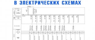
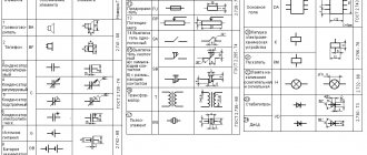
Designation of electrical elements on diagrams
To understand what exactly is shown on a diagram or drawing, you need to know the decoding of the icons that are on it. This recognition is also called blueprint reading. And to make this task easier, almost all elements have their own symbols. Almost, because the standards have not been updated for a long time and some elements are drawn by everyone as best they can. But, for the most part, symbols in electrical diagrams are in regulatory documents.
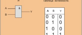
Symbols in electrical circuits: lamps, transformers, measuring instruments, basic components
Designation of measuring electrical instruments to characterize circuit parameters
| A heating element |
| UGO | Name |
| PF | Frequency meter |
| PW | Wattmeter |
| PV | Voltmeter |
| PA | Ammeter |
GOST 2.271-74 accepts the following designations in electrical panels for buses and wires:
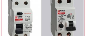
RCD designation on a single-line diagram
The main groups of RCD designations (graphic and alphabetic) are used very often by electricians. The work of drawing up work diagrams, schedules and plans requires very great care and accuracy, since a single inaccurate indication or mark can lead to a serious error in further work and cause the failure of expensive equipment.
In addition, incorrect data can mislead third-party specialists hired for electrical installations and cause difficulties when installing electrical communications.
Currently, any ouzo designation on a diagram can be represented in two ways: graphic and alphabetic.
Which regulatory documents should be referred to?
Of the main documents for electrical diagrams that refer to the graphic and letter designation of switching devices, the following can be distinguished:
- — GOST 2.755-87 ESKD “Conventional graphic designations in electrical circuits of devices, switching and contact connections”;
- — GOST 2.710-81 ESKD “Alphanumeric designations in electrical circuits.”
RCD designation on the diagram according to GOST
All residual current devices are marked on the diagrams using graphic and alphabetic images. This symbolism is determined by regulatory documents: GOST 2.755-87 ESKD “Conventional graphic symbols in electrical circuits. Switching and contact connection devices." Marking is determined in accordance with GOST 2.710-81 ESKD “Alphanumeric designations in electrical circuits.”
However, in general, these documents do not provide complete information about what exactly the RCD designation should be on a single-line type diagram. That is, no special requirements are put forward in this case. Therefore, many electricians mark some components and devices with their own developed meanings and labels, slightly different from the usual standard designations.
Sometimes the symbols printed on the body of the protective device are used as a basis. That's why. Based on the purpose of the RCD, this device is divided into two components on the electrical circuits - a switch and a sensor that responds to differential current and actuates the contact disconnection mechanism.
The current state standards (GOST) do not regulate the graphic and letter designation of RCDs (residual current devices); there are no additional graphic symbols that would allow a more precise description of the main functions and properties of standard equipment.
RCD is one of the main elements of single-line electrical circuits, therefore manufacturers of modular equipment and designers have adopted the following symbol for it:
Such a schematic display of residual current devices most accurately shows its operating principle and distinguishes it from other modular equipment, if you know what an RCD is and how it works.
At the same time, since state standards do not regulate the type of RCD, it is necessary to show on diagrams and plans a block with conventional graphic symbols (CGI), in which a transcript and explanations for the graphic elements must be given, even if it is decided to use a different type from the one presented. The ability to develop symbols yourself, if they are not in the standards, is indicated in GOST 2.702-2011.
The letter marking of the RCD is QF , if you use the rules for their formation according to GOST 2.710-81 ESKD (READ PDF) “Alphanumeric designations in electrical circuits.” This is completely identical to the designation of a circuit breaker and some other modular devices, making single line diagrams less readable and understandable.
Many people enter their own letter designations: Q, QFD, QDF, etc. which, if we rely on current standards, are incorrect, do not reveal the functions of the RCD, but help to distinguish them from other elements of protective automation on single-line diagrams.
This can be important, especially if the circuit simultaneously contains RCDs and automatic circuit breakers. Their graphic symbols are similar and it is not always easy to distinguish them from each other. Considering that electrical installation designers often simplify the graphic symbols used as much as possible, omitting important details.
Let's consider the conventional designation of a differential automatic machine on a single-line diagram and compare it with an RCD.
Electrical engineering cannot exist without the special circuits and projects accompanying it. Therefore, it is very important for a specialist to be able to read them correctly and use them exactly as intended. In many cases, all elements, including the RCD designation on a single-line diagram, are made rather conditionally, so that you can clearly imagine the complete picture of the entire graphic project. As a rule, the conventional image of an RCD resembles a regular switch, with poles, wires and other parts depicted symbolically. An experienced electrician is well versed in such diagrams, reads them confidently and does not make mistakes during work.
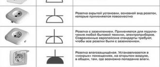
Representation of electrical equipment on plans
Although GOST 2.701-2008 and GOST 2.702-2011 provide for the type of electrical circuit “layout diagram”, when designing buildings and structures one should be guided by GOST 21.210-2014 “SPDS. Conventional graphic images of electrical equipment and wiring on plans.” This GOST establishes symbols for electrical wiring, busbar laying, busbars, cable lines, electrical equipment (transformers, electrical panels, sockets, switches, lamps) on plans for laying electrical networks.
These symbols are used when making drawings of electrical supply, power electrical equipment, electrical lighting and other drawings. Also, these designations are used to depict consumers in single-line circuit diagrams of electrical panels.
Conventional graphic images of electrical equipment, electrical devices and electrical receivers
| Name | Image |
| Electrical device. General image | |
| Electrical device, incl. with engine | |
| Device with generator | |
| Engine generator | |
| Complete transformer device with one transformer | |
| Complete transformer device with several transformers | |
| Complete condenser installation | |
| Complete converter installation | |
| Rechargeable battery | |
| Electric heating device. General designation |
Conventional graphic designations of wiring lines and conductors
| Name | Image |
| Wiring line, general image | |
| Wiring line indicating information (type of current, voltage, material, installation method, mark, etc.) | |
| Wiring line indicating the number of conductors (the number of conductors is indicated by serifs; if the number of conductors is more than three, numbers are used instead of serifs) | |
| Control line | |
| Line of emergency evacuation and security lighting networks | |
| Voltage line 36V and below | |
| Grounding and grounding line | |
| Grounding switches | |
| Open laying of wires and cables | |
| Rope gasket | |
| Gasket in tray | |
| Gasket in the box | |
| Gasket under the baseboard | |
| Gasket in pipe | |
| Release seal in pipes for hazardous areas | |
| Flexible wiring in a metal hose or flexible input | |
| Vertical gasket. The cable goes to a higher level or comes from a higher level | |
| Vertical gasket. The cable goes to a lower level or comes from a lower level | |
| Vertical gasket. The cable crosses the mark shown on the plan from top to bottom or bottom to top and has no horizontal sections within this plan |
Unfortunately, AutoCAD in the basic package does not contain all the necessary line types.
Designers solve this problem in different ways:
- most draw the wiring with a regular line, and then supplement it with symbols of circles, squares, etc.;
- Advanced AutoCAD users create their own linetypes.
I am a supporter of the second method, because... it's much more convenient. If you use a special type of line, then when you move it, all the “additional” symbols also move, because they are part of the line.
Creating your own linetype in AutoCAD is quite simple. You will spend some time mastering this skill, but you will save a lot of time later when designing.
It is most convenient to depict a vertical layout using AutoCAD blocks, or better yet, using dynamic blocks.
Conventional graphic images of tires and busbars
| Name | Image |
| Laying of busbars and busbars. General image | |
| Busbar laid on insulators | |
| Package of tires laid on insulators | |
| Busbars or busbar trunking on racks | |
| Busbars or busbar trunking on hangers | |
| Busbars or busbar trunking on brackets | |
| Trolley line | |
| Trolley line sectioning | |
| Tire compensator, trolley | |
| Note. The image of the mounting location of the busbar must correspond to its design position | |
It is convenient to draw buses and busbars in AutoCAD using polylines and/or dynamic blocks.
Conventional graphic images of boxes, cabinets, panels and consoles
| Name | Image |
| Branch box | |
| Introductory box | |
| Pull-out box, pull-out box | |
| Box, drawer with clamps | |
| Distribution cabinet | |
| Panel of group working lighting | |
| Group emergency lighting panel | |
| Laboratory shield | |
| Equipment box | |
| Control box | |
| Cabinet, panel, remote control, one-way service panel, local control station | |
| Cabinet, two-way service panel | |
| Cabinet, panel, remote control consisting of several panels for one-way operation | |
| Cabinet, panel, remote control consisting of several panels of two-way service | |
| Open shield | |
| Step-down transformer box (TSB) |
Rendering in AutoCAD is conveniently done using blocks and dynamic blocks.
Conventional graphic symbols of switches, switches
GOST 21.210-2014 does not provide conventional images for dimmers and a separate image for push-button switches, so I introduced my own designations for them in accordance with clause 4.7.
| Name | Image |
| Switch for surface installation with degree of protection from IP20 to IP23 | |
| single-pole | |
| single pole double | |
| single-pole triple | |
| bipolar | |
| three-pole | |
| Switch for flush installation with degree of protection from IP20 to IP23 | |
| single-pole | |
| single pole double | |
| single-pole triple | |
| bipolar | |
| Switch for open installation with a degree of protection not lower than IP44 | |
| single-pole | |
| bipolar | |
| three-pole | |
| Two-way switch without zero position with degree of protection from IP20 to IP23 | |
| open installation | |
| hidden installation | |
| Two-way switch without zero position with a degree of protection not lower than IP44 | |
| Dimmer (dimmer) for open installation with degree of protection from IP20 to IP23 | |
| Dimmer (dimmer) for hidden installation with degree of protection from IP20 to IP23 | |
| Dimmer (dimmer) for open installation with a degree of protection not lower than IP44 | |
| Push-button switch for open installation with degree of protection from IP20 to IP23 | |
| Push-button switch for hidden installation with degree of protection from IP20 to IP23 | |
| Push-button switch for open installation with a degree of protection not lower than IP44 |
It is convenient to draw in AutoCAD using dynamic blocks. I made myself one dynamic block for all types of switches.
Conventional graphic symbols of plug sockets
| Name | Image |
| Surface-mounted socket with degree of protection from IP20 to IP23 | |
| bipolar | |
| bipolar double | |
| two-pole with protective contact | |
| two-pole double with protective contact | |
| three-pole with protective contact | |
| a block of several computer sockets (the number indicates the number of sockets in the block) | |
| block of several household sockets (the number indicates the number of sockets in the block) | |
| Concealed socket outlet with degree of protection from IP20 to IP23 | |
| bipolar | |
| bipolar double | |
| two-pole with protective contact | |
| two-pole double with protective contact | |
| three-pole with protective contact | |
| a block of several computer sockets (the number indicates the number of sockets in the block) | |
| block of several household sockets (the number indicates the number of sockets in the block) | |
| Plug socket with a degree of protection of at least IP44 | |
| bipolar | |
| bipolar double | |
| two-pole with protective contact | |
| two-pole double with protective contact | |
| three-pole with protective contact | |
| a block of several computer sockets (the number indicates the number of sockets in the block) | |
| block of several household sockets (the number indicates the number of sockets in the block) |
It is convenient to draw in AutoCAD using dynamic blocks. I made myself one dynamic block for all types of sockets.
Conventional graphic symbols of lamps and spotlights
I am glad that the updated version of GOST has added images of LED lamps and lamps with compact fluorescent lamps.
| Name | Image |
| Lamp with incandescent lamp, halogen lamp | |
| Luminaire with compact fluorescent lamps | |
| LED lamp with a shape other than linear | |
| Lamp with linear fluorescent lamps (can also be shown to scale in the drawing) | |
| Linear LED lamp (can also be shown to scale in the drawing) | |
| Luminaire with high pressure discharge lamp | |
| Chandelier | |
| Slot light guide lamp | |
| Spotlight. General image | |
| A group of spotlights with the optical axis directed in one direction | |
| A group of spotlights with the optical axis directed in all directions | |
| Signal traffic light (three lamps) | |
| Wall lamp socket | |
| Suspended lamp socket | |
| Ceiling lamp socket | |
| Emergency lighting luminaire (example of a luminaire with an incandescent lamp) | |
| Lamp for special lighting (light indicator) |
It is convenient to draw lamps in AutoCAD using dynamic blocks.
Conventional graphic symbols of monitoring and control devices
| Name | Image |
| Call | |
| Siren, horn, howler | |
| Personnel call board for one signal | |
| Panel for calling personnel on several signals | |
| Advertising inscriptions and signs | |
| Starting device for electric motors. General image | |
| Magnetic switch | |
| Push-button post | |
| one button | |
| two buttons | |
| three buttons | |
| with two illuminated buttons | |
| two buttons with two signal lamps |
It is convenient to draw in AutoCAD using dynamic blocks.
Subscribe and receive notifications of new articles by e-mail
RCD connection diagram, RCD designation on the diagram, connection diagram for single-phase and three-phase RCD.
Installing an RCD significantly increases the level of safety when working on electrical installations. If the RCD has high sensitivity (30 mA), then it provides protection against direct contact (touch).
However, installing an RCD does not mean taking the usual precautions when working on electrical installations.
The test button must be pressed regularly, at least once every 6 months. If the test does not work, then you need to think about replacing the RCD, since the level of electrical safety has decreased.
Install the RCD on the panel or housing. Connect the equipment exactly according to the diagram. Turn on all loads connected to the protected network.
The RCD is triggered.
If the RCD trips, find out which device is causing the trip by sequentially disconnecting the load (we turn off the electrical equipment one by one and see the result). If such a device is detected, it must be disconnected from the network and checked. If the electrical line is very long, the normal leakage currents can be quite high. In this case, there is a possibility of false positives. To avoid this, it is necessary to divide the system into at least two circuits, each of which will be protected by its own RCD. You can calculate the length of the electrical line.
If it is impossible to determine in a documentary way the sum of leakage currents of wiring and loads, you can use an approximate calculation (in accordance with SP 31-110-2003), taking the load leakage current equal to 0.4 mA per 1 A of power consumed by the load and the leakage current of the electrical network equal to 10 μA per meter length of the phase wire of the electrical wiring.
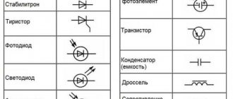
Basic designations
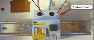
We will consider in more detail the order of labeling of a difavtomat (location of its characteristics) using the example of a domestic product of the “AVDT32” brand, used in protection circuits for industrial and household electrical networks.
For the convenience of systematizing the information presented, a graphic designation will be understood as a certain marking position.
The first position indicates the name and series of the automatic machine. From this designation it follows that it is a differential type AV with built-in protection against dangerous leakage currents. The difavtomat is intended for use in single-phase alternating current electrical networks with a rated voltage of 230 Volts (50 Hertz).
In the place corresponding to position No. 3 (above), such a characteristic as the value of the rated differential short-circuit current is indicated.
Sometimes in this place you can see the value of the maximum switching capacity of the device, indicating the value of the maximum current at which the automatic circuit breaker can be turned off many times.
At the same position, but below, there is a graphic designation of the type of built-in circuit breaker (in this case it is type “A”, designed to work with leakages of pulsating direct and sinusoidal alternating currents).
In place of the 4th position you can see a modular diagram of the difavtomat, which indicates the elements included in its composition that are involved in the implementation of protective functions. For RCBO32 in this diagram the following modules and assemblies are indicated by symbols:
- electromagnetic and thermal releases that provide protection of lines from short-circuit currents and overloads, respectively;
- a special “Test” button, necessary for manually checking the serviceability of the machine;
- amplification electronic module;
- executive unit (relay line switching).
At position number seven, the speed-related characteristic of the emergency operation of the electromagnetic release is indicated in the first place (for our example, this is “C”).
Immediately followed by the rated current indicator, indicating the value of this parameter in operating mode (over a long time).
The minimum shutdown (trigger) current of an electromagnetic type release for a difavtomat with characteristic “C” is usually taken equal to approximately five rated currents. With this current characteristic value, the thermal release operates in approximately 1.5 seconds.
In the eighth position there is usually a “delta” icon with an indicator of the rated leakage current, which turns off the differential device in case of danger. These are all the basic electrical characteristics.
List of the most important characteristics of automatic machines
Differential automatic machines (difavtomats) are designed on the principle of combining two protective functions in one device and have the capabilities of an automatic circuit breaker (AB) and an RCD.
As automatic devices, they protect power lines from overloads and short circuits (short circuits), and as RCDs, they protect a person from electric shock.
Important
The second protective function of these devices is explained by their ability to respond to the slightest leakage of electricity to the ground caused by a violation of the insulation of conductive parts or the touch of a living creature to them.
The built-in RCD circuit of a differential circuit breaker operates on the principle of comparing current components flowing in the forward and reverse branches of the controlled circuit. If the balance of these quantities is disturbed (the appearance of a current differential), the difference signal is sent to the executive relay, which instantly disconnects the dangerous section from the power line. What are the characteristics of difavtomats?
Operating current and speed
The design features of difavtomats are the reason that they have combined characteristics used in describing the operation of both AV and RCD. The main operating characteristic of these electrical products is the rated operating current, at which the device can remain turned on for a long time.
What do the inscriptions on the switch mean?
Symbols, numbers, letters, diagrams are applied to technical plastic with special indelible paint. Even with older models they remain readable. It is assumed that the user or electrician, barely glancing at the machine, should quickly determine its current characteristics and voltage.
Manufacturer and model of the machine
The top line of the marking block is occupied by the brand name. A certain color is selected for printing, often bright, and sometimes even by the shade you can determine which manufacturer’s products are in front of you.
Experienced electricians suggest not to skimp when buying machines and to purchase devices only from proven European brands: Schrack Technik , Schneider Electric , ABB , Schaltbau , Moeller , HAGER , Legrand . There are several Russian brands that you can also safely trust: Elektrotechnik , TDM ELECTRIC , EKF .
The line below indicates the device model. All other inscriptions, except for the manufacturer's name, are usually printed in gray, so the series can be easily confused with technical specifications.
In order not to be mistaken, we look exactly at the second line. The line or model designation may look like this: BA63 , SH200 , Acti9 .
You can try to decipher the series, but the technical characteristics are not always hidden behind the letters and numbers; more often it is just the name of a specific model.
The line designation can be printed either on a general gray background or on a colored line, which is located directly under the brand.
Determination of time-current characteristic
The next line is a combination of a Latin letter and a number. The first letter indicates the time-current characteristic. It refers to how quickly a switch operates when a certain amount of current flows through it. There are five different types in total: “B”, “C”, “D”, “K”, “Z”, but in everyday life machines B, C, D are used.
Trip current and voltage
The group of technical characteristics of the difavtomat includes the circuit shutdown current (differential indicator), defined as the “current leakage setting”. For most models, the permissible values of this characteristic fall into the following series: 10, 30, 100, 300 and 500 milliamps. On the body of the difavtomat it is indicated by the “delta” icon with a number corresponding to the leakage current.
Another characteristic of the operational capabilities of difavtomats is the rated voltage at which they are able to operate for a long time (220 Volts for a single-phase network and 380 Volts for three-phase circuits). The operating voltage of the protective differential device can be indicated under the rating designation with a letter or under the switch key.
Uzo designation on the diagram
To protect against current leakage, residual current switches or residual current devices (RCDs) are used. In every new apartment, new house, this device becomes a necessary equipment.
However, devices with a fundamentally different internal design, which determines the reliability of the entire RCD, can be sold under a common name. The design may have a different arrangement of levers and control buttons, have standard or expanded options for connecting buses and wires, but the design of the RCD release . It can be electromechanical or electronic. But how can you immediately distinguish an electromechanical RCD from an electronic one? This issue needs to be discussed in detail.
What is the difference between an electromechanical RCD and an electronic one?
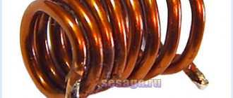
RCDs and difavtomats (this is an RCD and a circuit breaker in one housing) according to their internal design are divided into two types: electromechanical and electronic . This does not affect the operating parameters and technical specifications in any way. Many people immediately have a question: what is their difference? But there is a difference, and an important one: an electromechanical type RCD will work in any case if a leakage current appears in the damaged area, regardless of whether there is voltage in the network or not. The main working module of an electromechanical RCD is a differential transformer (toroidal core with windings). If a leak occurs in the damaged area, then a voltage appears in the secondary winding of this transformer, which turns on the polarized relay, which in turn triggers the shutdown mechanism.
Electronic RCDs are triggered when there is a current leak in the damaged area and only when there is voltage in the network. That is, for full operation, an electronic type residual current device requires an external power source. This is due to the fact that the main operating module of electronic RCDs is an electronic board with an amplifier. And without external power this board will not work.
RCD or differential circuit breaker: visual differences
It is difficult for an uninitiated person to understand what device is in front of him. Externally, the RCD is practically no different from the RCBO. However, it will be quite easy for a knowledgeable home handyman to figure it out. So how to distinguish an RCD from a difavtomat visually? The main thing here is to understand what the markings on the front panel mean.
With Russian-made products everything is quite simple. They clearly indicate what device a person is holding in his hands. “Difavtomat” or “AVDT” can be printed on the front panel. If there are no such markings, you need to pay attention to the alphanumeric designation.