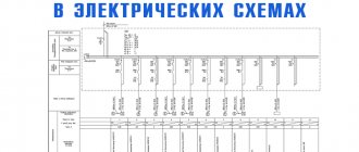
Symbols in GOST Electrical Diagrams
It is also divided into dry and oil, depending on the cooling method.
The language of modern circuits emphasizes in symbols the main functions that the depicted element performs in the circuit. H - Joint at intersection.
This standard applies to manual or automated diagrams of products from all branches of industry and construction and establishes conventional graphic symbols for switching devices, contacts and their elements. Wiring diagrams and markings of electrical circuits
For example, there are several equivalent options for designating switching contacts, as well as several standard designations for transformer windings. Their images are placed on panels.
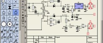
The dimensions of individual graphic symbols and the ratio of their elements are given in the Appendix. These diagrams are very diverse, with different functions, however, all graphic symbols are given the same form and correspond to the same elements in all diagrams. Definition of the concept of an electrical circuit, according to GOST 2. Conceptual drawings are created both single-line and complete.
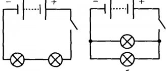
Fundamental - they indicate in detail the connections, contacts and characteristics of each element for networks or devices. Quartz filter ZQ Sequential numbers of elements should be assigned, starting from one, within a group of elements that are assigned the same letter position designation in the diagram, for example, Q1, Q2, Q3, in accordance with the sequence of their location in the diagram from top to bottom and from left to right. To depict the main basic functional characteristics of switching devices, conventional graphic designations of contacts are used, which can be made in a mirror image: 1 closing 3 switching 4 switching with a neutral central position 1. For example, there are three types of contacts - making, breaking and switching.
How to Read VAG Wiring Diagrams, Part 2
Technical characteristics and operating conditions
Despite the huge variety of models available for sale, their technical characteristics are the same, but may differ slightly in parameters:
- Rated voltage (in the case of alternating current – up to 660V, with direct current – up to 440V).
- Lowest operating voltage (with alternating current - from 36, with direct current - from 24).
- Rated voltage across the insulating layers (up to 660V).
- Rated current (10A).
- Through current flowing through the push-button post for one second (200A).
- Nominal operating mode (there can be 4 types: short-term, intermittent, long-term and intermittent-long).
Operation largely depends on the type of control station, but there are a number of general points:
- First of all, the push-button post should not be located above 4300 m above sea level.
- The temperature in a workshop or other work area can be from -40 to +40 degrees.
- If the humidity regime exceeds 80% at a temperature of 20 degrees, then this will soon lead to damage to the contacts; at a temperature of 40 degrees, this figure should not exceed 50%.
- There are devices that can operate in explosive environments, but most models are not designed for this.
- In addition, the environment should not contain large amounts of dust that can conduct electric current, corrosive gas and water vapor.
- It is strictly prohibited to expose the structure to direct sunlight.
What types of electrical circuits might be useful?
Let's consider the design information from the point of view of an amateur electrician who wants to change the wiring in the house with his own hands or draw up a drawing for connecting the dacha to electrical communications.
First you need to understand what knowledge will be useful and what will not be needed. The first step is to become familiar with the types of electrical circuits.
All information about the types of circuits is presented in the new edition of GOST 2.702-2011, which is called “ESKD. Rules for the execution of electrical circuits."
This is a duplicate of an earlier document - GOST 2.701-2008, which talks in detail about the classification of circuits. There are 10 types in total, but in practice only one may be required - electric.
In addition to the type classification, there is also a standard one, which divides all drawing documents into structural, general, etc., with a total of 8 points.
The home craftsman will be interested in 3 types of diagrams: functional, schematic, installation.
Type #1 – functional diagram
The functional diagram does not contain details; it indicates the main blocks and assemblies. It gives a general idea of how the system works. For the electrical supply of a private home, it does not always make sense to draw up such drawings, since they are usually standard.
Main types of symbols according to GOST
Electrical diagrams belong to technical drawings and are one of their varieties. They display all the components of certain circuits, indicated by special symbols. They are divided into several main groups, including various types of consumers, current sources, control elements and conductors.
Their graphic representations are applied to the drawing, using lines of different thicknesses and ordinary geometric shapes. They can be square and rectangular, in the form of a circle or arc, triangle, simple line and dotted line, etc. All these symbols include not only graphics, but also symbols consisting of letters and numbers. Applied all together, they interact with each other according to the established system and are able to display any hardware and equipment, connecting lines with mechanics, electrical networks, all kinds of windings, switching means and other similar components.
The composition of the schematic diagrams can be supplemented by specially developed UGOs that explain the specifics of the action of certain components. As a living example, we can take the different types of contacts used for making, breaking and switching. The general symbolism provided by GOST corresponds to only one direction of operation of these devices - closing and opening a given circuit. All additional functionality is indicated by symbols on the moving contact part. Using this symbolism, the required element can be easily identified on any diagram - relays, buttons, contactors, starters, etc.
Some types of parts and components may appear in more than one appearance. This applies to transformer windings, switching contacts and other components that are used in these conditions. In the event that the standard list does not contain the required designation, it is compiled independently, based on the operating principle of the given element. As a basis, icons are used that are used to display similar equipment.
Read also: Template for cutting depth limiter
A huge number of graphic UGO icons and their combinations represent a detailed element base, indispensable when making all kinds of electrical drawings and diagrams. Images are drawn according to established standards, observing line width, dimensions and other parameters. All types of schemes are divided into several components. According to their purpose, they are single-line, installation and principle type.
Graphics and symbolism in single-line diagrams
The main function of single-line schematic images is a graphic displaying a particular power supply system of a given facility. It displays the connection of the general power supply and subsequent wiring to individual points. This drawing is made in the form of one general line, which is why it is called single-line. That is, the power supply to each of the consumers is plotted on the plan in the form of a single line.
The symbol for the number of phases in the graphical version is displayed using specially marked marks. If there is one notch, the power supply is single-phase, and if there are three, it is three-phase.
In addition to single linear networks, equipment for switching and protection is applied to the circuit. The first group is represented by contactors, magnetic starters, disconnectors, and the second includes various types of automatic machines, high-voltage circuit breakers, RCDs, safety devices, automatic circuit breakers and load switches.
Small squares are used to display high voltage power switches on a single line diagram. Other protective and switching equipment is applied to the diagram in the form of icons displaying contacts with specific explanatory inscriptions corresponding to the specific device being used.
Basic UGO for single-line diagrams of electrical panels
| UGO | Name |
| Thermal relay | |
| Contactor contact | |
| Switch - load switch | |
| Automatic - circuit breaker | |
| Fuse | |
| Differential circuit breaker | |
| RCD | |
| Voltage transformer | |
| Current transformer | |
| Switch (load switch) with fuse | |
| Motor protection circuit breaker (with built-in thermal relay) | |
| A frequency converter | |
| Electricity meter | |
| Normally closed contact with reset button or other push-button switch, with reset and opening by means of a special actuator of the control element | |
| Normally closed contact with push-button switch, with reset and opening by retracting the control button | |
| Normally closed contact with push-button switch, reset and open by pressing the control button again | |
| Normally closed contact with push-button switch, with automatic reset and opening of the control element | |
| Delayed closing contact that initiates upon return and operation | |
| Delayed closing contact which only operates on return | |
| Delayed closing contact which is only initiated when triggered | |
| Delayed closing contact which is actuated by return and tripping | |
| Delayed closing contact which only operates on return | |
| Delayed closing contact that only switches when triggered | |
| Timing relay coil | |
| Photo relay coil | |
| Pulse relay coil | |
| General designation of a relay coil or contactor coil | |
| Indication lamp (light), lighting | |
| Motor drive | |
| Terminal (separable connection) | |
| Varistor, surge arrester (surge suppressor) | |
| Arrester | |
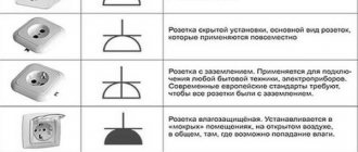
| Socket (plug connection): |
- Pin
- Nest
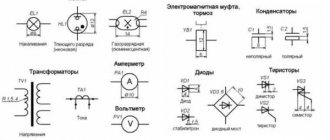
Designations in email diagrams
Alphanumeric designations in electrical circuits. GOST 2.710-81 (fragment).
Letter codes for the most common types of elements.
Examples of two-letter codes
Examples of element types marked * added by the author.
Comments
1. If the UGO is not established by the standards, then the developer performs the UGO in the margins of the diagram and gives explanations (GOST 2.702-2011). That is, if the standards do not contain a symbol for an electrical device, you can come up with your own (preferably using the symbol elements available in the standards). And on the free field of the drawing, display this designation and give an explanation of its purpose and function. For example a photocapacitor:
2. According to the letter designation, if in the standards all photocells: a photoresistor, a photodiode, and a phototransistor are designated the same - BL, then it would probably be more logical to assign the same letter code BL to the photocapacitor.
3. A photoelectrochemical supercapacitor, upon quick acquaintance, combines a semiconductor solar cell with a supercapacitor itself. Perhaps it can be depicted this way:
Use the same letter code at your discretion (perhaps in this case, you can use the designation for the power source - G) and decipher it in the explanations. But, this is speculative. I need to study the design more carefully (I don’t have time for that)
Good day! I am very interested in 3 questions. 1. How are photocapacitors designated on electrical circuits (logically, the designation should be similar to a photoresistor: take the element itself (the capacitor in this case) in a circle and put 2 arrows directed at it; but the problem is that I have not found any confirmation of this both in catalogs and in general in articles on the Internet). 2. If a designation for an element does not yet exist, can it be designated by a combination of letters, or by a combination of an element and letters? For example, in this case, let there be no designation photocapacitor a. Which of the following options can you then designate it with: three letters “BLC” or “CBL”, taken in a circle (by the way, if this is correct, then which of these 2 options is correct?), or draw a capacitor and put the letters next to it "BL"? 3. How are the subtypes of elements indicated on electrical diagrams? For example, there is a photoelectrochemical supercapacitor (PES photocapacitor, from the English Photoelectrochemical Supercapacitor). How to indicate it on the diagram? A capacitor with the letters PES next to each other? Or again, a combination of some letters, for example, “PES-C” (by the way, a question purely out of curiosity: if this designation is correct, then is it necessary to put a hyphen?)? Sorry for asking so many questions (probably stupid ones at that)! I'm not very knowledgeable in this area. But I really really need this. Thank you in advance!
Letter designations
In addition to the fact that the elements on the diagrams have conventional graphic names, they have letter designations, which are also standardized (GOST 7624-55).
The push-button station is designed for switching circuits designed to control alternating current, the voltage of which is up to 660 V with a frequency of 50 and 60 Hz. In addition, they can be used in DC circuits with voltages up to 440 V or for supplying control signals. The latter can be performed either remotely or on site.
Typically, such products are needed to control devices of various types at a distance.
The design of the control panel is quite simple, there are a minimal number of parts in it, but there is one very important function - to issue commands and check how completely they have been executed.
They are used in automatic systems, in particular, such devices can be placed in metal and woodworking machines, various types of mechanisms aimed at lifting and moving loads.
Its body is usually made of plastic, there are at least 2 control elements, but there can be much more.
Its pusher is mushroom-shaped or made in the shape of a cylinder. Cylindrical products are available in black, white, yellow, red, blue or green. The mushroom-shaped pusher is painted red or black.
The contact elements operate via both the making and breaking principles.
Explosion-proof models are used to remotely control electric drives of stationary or mobile installations. These devices can be used in the gas and oil industries, as well as in other types of industrial production.
magnetic switch
This system is quite flexible and is equipped with several modules, as well as a magnetic starter. The latter is connected directly through a push-button post, due to which the reliability of its operation becomes very high.
This starter is a switching structure, due to which electricity is disconnected or connected.
Such starters have a metal or plastic body and can be used in direct or alternating current networks. They are often used in automated systems and devices; in addition, they are designed to turn systems on or off in the event of an emergency.
They can be remote or built directly into the design of the product.
In order for the entire system to operate as reliably as possible, only those electrical products are used that will directly correspond to all existing characteristics.
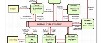
Types and types of electrical circuits
It is required to place coding of elements on electrical diagrams. There are three types of drawings:
- functional;
- principled;
- mounting.
Functional
The plan indicates the main components of the electrical device. The drawing represents a certain number of rectangles, between which connecting lines are drawn. The name of the functional block is written inside each figure.
Principal
The plan contains a network connecting radioelements into a single system. The same applies to the layout of electrical networks. On the diagram, all parts are marked. Conceptual drawings are created both single-line and full. The single-line construction plan conveys an image of only power circuits. Control controls are placed on a different drawing. They do this because of the cumbersome nature of electrical circuits.
Important! When the structure of instruments or devices is not particularly complex, the drawings are combined into a single plan, which is called a complete diagram.
Mounting
Unlike the above drawings, the wiring diagram, in addition to indicating the elements, determines their exact position in two-dimensional space. The wiring of the electrical network in a house or apartment is depicted with the exact position of sockets, switches, lamps and other devices. Indicate the distances from the elements to the wall fences. On radio installation diagrams, the position of radio components, methods and order of their installation are noted.
Device and design
simple diagram of posts
The standard push-button control station has the following design features:
- Each of the buttons does not have a fixed position.
- The “Start” button is usually painted green, and sometimes even backlit when turned on; it also has normally wired contacts; it itself is used to activate the operation of a particular mechanism.
- The “Stop” button is usually red and is located on closed contacts. Due to this, the supplied voltage is removed from the device and its operation is suspended.
- In addition, push-button control stations can have a metal or plastic body. Each of them has its own level of protection. They are allowed to be used in devices intended for distribution purposes, as well as in the automation of most industrial systems.
- The push-button station is the basis of the design of most remote controls; it is directly involved in turning the equipment on or off, and acts in an emergency.
If the equipment is dangerous to human life or health, similar devices are produced with an increased degree of protection. The connection diagram in this case is much more reliable, and the remote control itself can be connected to various devices.
Often, the installation is controlled from 2 points. As a rule, this is caused by a certain production need. Typically, various electric motors operate using this technology, but other equipment can also operate.
Image of a contactor on schematic diagrams
The structure of all basic electrical plans includes the most complete drawing, with all components, connections between them, letter symbols and technical characteristics of the equipment. It is used as a basis for drawing up single-line and wiring diagrams, and its graphics include the power part and control circuits.
Operating or control circuits include all categories of buttons, contactor coils or magnetic starters, fuses, contacts of various relays, contactors and starters. This also includes phase voltage control relays and all connecting links between components. The power part consists of circuit breakers, power contacts of starting devices, electric motors and other equipment.
Graphic displays of all elements, including the designation of the contactor on the diagram, are accompanied by additional symbols consisting of letters and numbers. They are contained in specially created tables determined by regulatory documents. Several identical devices are marked with corresponding numbers in order of location.
If there are types of relay devices in the plan diagrams, they certainly use at least one blocking contact of this device. An intermediate relay, if present in the circuit, can have two or more contacts, which are assigned their own numbers. The numbering includes the serial number of the relay, and then, after the dot, the number of the specific contact is indicated. The block contacts of automatic machines, contactors, starters, and other types of relays are numbered in exactly the same order.
If the need arises, graphics, letters and numbers of individual types of elements are supplemented with their brief parameters. For example, for automatic machines the value of the rated current (A) and the cut-off current (A) is indicated. Contactor markings include the current rating, as well as the type and model of the specific device.