Designations in email diagrams
The rules for implementing normal electrical connection diagrams for electric power facilities are defined by two standards. This is the Organization Standard of JSC FGC UES STO 56947007-25.040.70.101-2011 Section 2 and GOST R 56303-2014.
Despite the fact that at the moment both standards are valid and define the requirements for the implementation of the same types of circuits, the requirements in them are somewhat different (probably the developers of the standards are not friends...).
In this material, when compiling examples of graphic designations of elements of electrical connection diagrams of electric power facilities, GOST R 56303-2014 is taken as a basis, since it is newer in terms of the date of entry into force. If the type of graphic symbols given in the examples of the STO 56947007-25.040.70.101-2011 standard differs from the similar ones given in GOST R 56303-2014, appropriate notes have been added.
Color options for voltage classes.
| Voltage class | GOST R 56303-2014 | STO 56947007-25.040.70.101-2011 | ||
| Color name | Spectrum (RGB) | Color name | Spectrum (RGB) | |
| 1150 kV | lilac | 205:138:255 | lilac | 205:138:255 |
| 800 kV | Navy blue | 0:0:168 | Navy blue | 0:0:200 |
| 750 kV | Navy blue | 0:0:168 | Navy blue | 0:0:200 |
| 500 kV | red | 213:0:0 | red | 165:15:10 |
| 400 kV | orange | 255:100:30 | orange | 240:150:30 |
| 330 kV | green | 0:170:0 | green | 0:140:0 |
| 220 kV | yellow-green | 181:181:0 | yellow-green | 200:200:0 |
| 150 kV | khaki | 170:150:0 | khaki | 170:150:0 |
| 110 kV | blue | 0:153:255 | blue | 0:180:200 |
| 60 kV | lilac | 255:51:204 | — | — |
| 35 kV | brown | 102:51:0 | brown | 130:100:50 |
| 20 kV | bright purple | 160:32:240 | brown | 130:100:50 |
| 15 kV | bright purple | 160:32:240 | — | — |
| 10 kV | violet | 102:0:204 | violet | 100:0:100 |
| 6 kV | dark green | 0:102:0 | light brown | 200:150:100 |
| 3 kV | dark green | 0:102:0 | — | — |
| below 3 kV | grey | 127:127:127 | — | — |
| up to 1 kV | — | — | grey | 190:190:190 |
Conventional graphic designations of elements of normal electrical connection diagrams of electric power facilities.
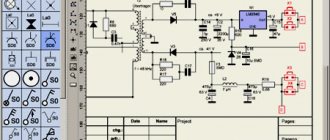
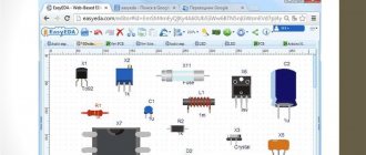
In the examples, conventional graphic symbols from the Visio stencil library are used. Normal PS diagram.
The modular grid pitch is 2.5 mm.
The thickness of symbol lines and electrical communication lines is 0.4 mm (According to the standard, from 0.2 to 1.0 mm. Recommended - from 0.3 to 0.4 mm.)
Graphic designation of transformers.
| Name | Designation | |
| 1. | The transformer is two-winding. | |
| 2. | Three-winding transformer. | |
| 3. | Four-winding transformer. | |
| 4. | Five-winding transformer. | |
| 5. | Two-winding autotransformer. | |
| 6. | Three-winding autotransformer. | |
| 7. | Four-winding autotransformer. | |
| 8. | The auxiliary transformer is two-winding. | |
| 9. | Three-winding auxiliary transformer. | |
| 10. | The voltage transformer is two-winding. | |
| 11. | Three-winding voltage transformer. | |
| 12. | Four-winding voltage transformer. | |
| 13. | Current transformer | |
| 14. | Current transformer with two windings: on a common core and on separate cores. | |
| 15. | Booster. | |
| Notes: | ||
| 1. | Each winding of an autotransformer and transformer must be made in a color corresponding to the voltage class for which it is made. The possibility of adjustment on the equipment and symbols of methods for connecting the transformer windings must be displayed with a black arrow. | |
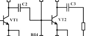
Graphic designation of switching devices.
| Name | Designation | |
| 1. | Switch. | |
| 2. | Disconnector. | |
| 3. | Load switch. | |
| 4. | Load break switch is an alternative symbol (used by some organizations). | |
| 5. | Circuit breaker. | |
| 6. | Withdrawable circuit breaker trolley. | |
| 7. | Retractable disconnector. | |
| 8. | Withdrawable load switch trolley. | |
| 9. | Withdrawable load switch trolley is an alternative symbol. | |
| 10. | Withdrawable circuit breaker trolley | |
| 11. | Roll-out disconnector trolley. Working, repair and control position. | |
| 12. | Grounding disconnector. | |
| 13. | Short circuit without ground. | |
| 14. | Short circuit. | |
| 15. | Separator | |
| 16. | Double acting separator | |
| 17. | 3-position spacecraft. On, off and grounded positions. | |
| Notes: | ||
| 1. | Repair and control positions of the roll-out trolley. Similarly for items 7-10. | |
| 2. | Withdrawable circuit breaker trolley according to STO 56947007-25.040.70.101-2011. The switch position is on, the repair and control position of the trolley. | |
Graphic designation of compensation devices and filters.
| Name | Designation | |
| 1. | Single current-limiting reactor. | |
| 2. | Double current-limiting reactor. | |
| 3. | Current-limiting reactor. | |
| 4. | Choke coil with core and adjustable, without core. High frequency power line suppressor. | |
| 5. | Arc suppression reactor without regulation and with regulation. | |
| 6. | Synchronous compensator. | |
| 7. | Asynchronized synchronous compensator. | |
| Barrier filter. | ||
| 8. | Capacitor. | |
| 9. | Capacitor battery. | |
| 10. | Static capacitor bank. | |
| 11. | Longitudinal compensation device | |
| 12. | Adjustable longitudinal compensation device. | |
| 13. | Connection filter. | |
| Notes: | ||
| 1. | The symbol should be in a color corresponding to the voltage class of the device, and the regulation symbol should be black. For example, a current-limiting adjustable reactor. | |
Graphic designation of arresters, arresters.
| Name | Designation |
| 1. | Arrester. |
| 2. | Tubular arrester. |
| 3. | Ball arrester. |
| 4. | The arrester is horny. |
| 5. | Spark gap. |
| 6. | Valve and magnetic valve arrester. |
| 7. | Valve arrester. |
| 8. | SPD is a nonlinear voltage limiter. |
Graphic designation of generators, electric motors.
| Name | Designation |
| 1. | Generator. |
| 2. | Diesel power station. |
| 3. | Engine. |
| 4. | The motor is synchronous. |
| 5. | The motor is asynchronous. |
Graphic designation of fuses.
| Name | Designation |
| 1. | The fuse is fusible. |
| 2. | Fuse. |
| 3. | The fuse is slow-moving. |
| 4. | The fuse is broken. |
| 5. | The fuse is on the cart. |
| 6. | The fuse is on the cart. |
| 7. | Inertial fuse on the trolley. |
| 8. | Switch-fuse: open position, closed position. |
| 9. | Withdrawable fuse-disconnector trolley: open position, closed position. |
| 10. | Withdrawable fuse-disconnector trolley: repair and inspection positions. Similarly for items 5-7. |
Graphic designation of electrical communication lines, buses, grounding.
| Name | Designation | |
| 1. | Electrical communication line, busbar. | |
| 2. | PTL - power transmission line. Displayed as thick lines (a twofold or greater increase in thickness in relation to the lines used to make the UGO and busbar). | |
| 3. | Cable line. An electrical communication line with one branch may be depicted without a dot. | |
| 4. | Crossing electrical communication lines. | |
| 5. | Electrical communication line branches. The connection point must be made in a color corresponding to the voltage class of the electrical communication lines. An electrical communication line with one branch may be depicted without a dot. | |
| 6. | Tire. They should be made in a color corresponding to the voltage class, and the connection points for the taps should be white. | |
| 7. | Grounding. | |
| Notes: | ||
| 1. | For power lines (clauses 2.3), no special instructions were found in STO 56947007-25.040.70.101-2011. Probably, their thickness, according to this standard, is equal to the thickness of electrical communication lines. | |
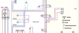
An example of an image of a normal electrical connection diagram of a conditional substation, made in accordance with GOST R 56303-2014 (PDF format).
The diagram was made in Visio using the stencil library:
Normal ES diagram
How to draw a normal electrical connection diagram for an electrical power facility (electrical substation, switchgear)
Operational diagram and layout of electrical connections of power plants and substations
The basic requirements for operational circuits and layout circuits are set out in the above paragraph 10.1 “Instructions for switching in electrical installations”.
On the prepared operational diagrams of electrical connections of power plants and substations, all switching devices and stationary grounding devices are depicted in a position (on or off) corresponding to the normal mode diagram approved by the chief engineer of the station or electrical network enterprise.
The equipment of new connections, to which voltage can be supplied by turning on the switching devices, is considered operational and is plotted on the operational diagram.
Operational diagrams and layout diagrams reflect all changes in the positions of switching devices, relay protection and automation devices, the location of portable grounding and the inclusion of grounding knives.
When returning to duty, the personnel hand over to the shift an operational diagram (layout diagram) of the electrical installation indicating on it the actual positions of the switching devices, disconnected relay protection and automation devices, as well as grounding devices.
The actual positions of switching devices, disconnected relay protection and automation devices and grounding devices are indicated by applying symbols on the operational diagram directly to the graphic designation of the device or next to the graphic designation of the corresponding device (device), if the position of the device (device) has been changed.
Signs are applied with pencil, ink or red paste.
Sign "Z!" - relay protection device is disabled - placed next to the graphic designation of the protected equipment (generator, transformer, line, busbars).
Sign "A!" - the automation device is disabled - is applied next to the graphic designation of the switch that is affected by the automatic device.
When removing portable grounding from equipment, as well as when switching on a previously disconnected relay protection or automation device, the corresponding signs on the operational diagram are crossed out with a pencil, pen (ink or paste) of a dark color.
Correction of erroneously applied signs is not permitted. Incorrect signs are circled in blue, and correct signs are placed next to them.
The duration of the operational scheme is not limited; a new operational plan is drawn up as needed.
The operational scheme has a serial number. When handing over the duty, the operational scheme is signed by the person handing over and taking over the duty, indicating the date and time.
When using layout diagrams, maintaining operational diagrams is not necessary.
On the layout diagrams, all changes in the positions of switching devices, relay protection and automation devices, grounding devices are reflected using symbols of switching devices and hanging conventional signs. The procedure for maintaining a layout diagram of an electrical installation is indicated in the instructions of the power company.
It is allowed to maintain an operational diagram on a computer. The procedure for maintaining an operational diagram on a computer is also established in the instructions of the energy company.
Switching forms
A switching form (usual) is an operational document that provides a strict sequence of operations with switching devices, grounding disconnectors (knives), operational current circuits, relay protection devices, emergency and operational automation, operations to check the absence of voltage, applying and removing portable groundings , hanging and removing posters, as well as necessary (according to the conditions of personnel safety and equipment safety) inspection operations.
A standard switching form is an operational document that specifies a strict sequence of operations when performing repeated complex switching in electrical installations of different control levels or different power facilities.
Switching forms establish the order and sequence of operations when carrying out switching in electrical connection diagrams of electrical installations and relay protection and automation circuits.
Using switching forms, complex switchings are performed, as well as all switchings (except single ones) on electrical installations that are not equipped with interlocking devices or have faulty interlocking devices.
Along with conventional switching forms, standard programs and standard switching forms are developed and used for repeated complex switchings.
Complex ones include switching that requires a strict sequence of operations with switching devices, grounding disconnectors and relay protection devices, emergency and regime automation. When performing the sequence of operations specified in the programs and switching forms, the safety of operating and maintenance personnel is ensured and the occurrence or development of disturbances in the operation of the electrical installation is prevented.
When making complex switchings, replacing forms or switching programs with any other operational documents is not allowed.
For each power plant, substation and electrical installation of distribution power grids, lists of switching types performed using conventional switching forms, standard forms and switching programs are developed, as well as a list of switching types that can be performed without switching forms. Each list indicates the number of operational personnel involved in certain switches.
Lists of complex switchings, approved by the technical managers of the relevant power facilities, are stored at control centers, central (main) control panels of power plants and substations.
Lists of complex switchings are revised when the circuit, composition of equipment, and relay protection and automation devices change.
The usual switching form is drawn up by operational or operational-repair personnel who will make switches after recording the order in the operational log.
It is allowed to draw up a switching form by the specified personnel in advance during the shift.
Standard switching forms are developed in advance by the personnel of power enterprises in relation to complex switchings in the main electrical connection circuit of an electrical installation, in auxiliary circuits, and relay protection and automation devices, taking into account the fact that switchings containing operations with secondary switching equipment in emergency system automation circuits are among the complex ones.
Standard switching forms are signed at power plants by the heads of electrical shops and their deputies for relay protection and automation; at electrical network enterprises - heads of dispatch services and heads of local relay protection and automation services.
Standard forms for switching to substations are agreed upon with the heads of the relevant dispatch service, in whose operational management the equipment is located, and approved by the chief engineer of the enterprise.
Switching programs (standard programs) are used by operational managers when making switching in electrical installations of different management levels and different power facilities.
The switching program is approved by the head of the dispatch control, who is operationally subordinate to all switched equipment.
The level of detail of programs is taken to correspond to the level of dispatch control.
Persons directly performing switching operations are permitted to use the switching programs of the corresponding dispatcher, supplemented by switching forms.
Standard programs and switching forms are promptly adjusted in the event of changes in the main electrical connection diagram of electrical installations associated with the introduction of new equipment, replacement or partial dismantling of obsolete equipment, reconstruction of the switchgear, as well as the inclusion of new relay protection and automation devices or changes in electrical installations.
With planned changes in the circuit and operating modes of the power system and changes in relay protection and automation devices, the production services of power systems, which manage the equipment and relay protection and automation devices, make the necessary changes and additions in advance to standard programs and switching forms at the appropriate levels of operational management.
Switching forms (standard forms) are used by operational dispatch personnel who directly perform switching.
Switching forms establish the order and sequence of operations when carrying out switching in electrical connection diagrams of electrical installations and relay protection and automation circuits.
The switching form (regular and standard) records all operations with switching devices and operational current circuits, operations with relay protection and automation devices (as well as with the power circuits of these devices), operations on turning on and off grounding blades, applying and removing portable groundings, phasing operations equipment, results of inspection of support-rod insulators (presence of cracks and chips) before performing operations with disconnectors, operations with telemechanics devices and others in a certain sequence of their implementation.
The switching forms indicate the most important personnel check actions:
checking the absence of voltage before applying grounding (turning on grounding blades) to live parts;
on-site check of the switched-on position of the busbar before commencing operations to transfer connections from one bus system to another;
on-site check of the open position of the switch, if the next operation is with disconnectors;
checking on site or using signaling devices the position of each switching device of the primary circuit after the device has performed an operation;
checking at the end of the switchings the compliance of the switching devices in the relay protection and automation circuits with the regime cards.
Each operation (or action) in the switching form is recorded under a serial number.
Immediately before switching using a regular switching form, the correctness of the operations recorded in it is checked using an operational diagram (or layout diagram), which accurately reflects the actual position of the switching devices of the electrical installation at the time of verification.
After checking, the switching form is signed by two persons - those performing the switching and those monitoring them.
When switching is carried out by one person from the operational staff, the correctness of the switching form is controlled by the operational manager who gave the order for the switch, and his name is entered on the form.
At power plants, when the shift supervisor of the electrical shop (as a supervisor) and the electrician on duty (as the one performing the operations) participate in switching operations, the inscription “I authorize switchings” is written on the switching form, signed by the power plant shift supervisor.
When using standard switching forms, the following conditions are met:
the decision to use a standard switching form when performing specific operations is made by the person performing the switching and the supervisory person;
the standard switching form indicates for which connections, when performing which task and for which electrical installation diagram it can be used;
Before starting switching, the standard switching form is checked against the operational diagram or layout diagram of the electrical installation by the supervisor. On checking the standard switching form and the correctness of the sequence of operations and verification actions set out in it, in the operational log after recording the dispatcher's order for switching, a record is made that the corresponding standard switching form has been checked, corresponds to the diagrams and switching in the sequence specified in it can be performed. It is allowed to make the specified entry in the standard switching form signed by the person performing the operations and the person controlling the switching data;
It is not allowed to use a standard switching form if the electrical installation diagram or the state of the relay protection and automation devices does not correspond to the diagram for which the standard form was drawn up. Operational personnel are not allowed to make changes or additions to the standard switching form if it corresponds to the scheme and specifications;
if changes have occurred in the primary connection diagram or in the electrical installation circuits that exclude the possibility of performing operations on individual items of the standard switching form, or errors are found in it, the operating personnel of the power plant, the substation makes an appropriate entry in the operational log and informs the persons who signed the standard form about this switches, or persons replacing them by position, as well as the operational manager. The use of a standard form in this case is not permitted; a regular switching form is drawn up;
in the case when, when using a standard switching form for carrying out the next operation on a given electrical installation, it is necessary to receive an order from the dispatcher (for example, an order to turn on the grounding knives on a disconnected power line), in the standard switching form, before recording this next operation, an o.
In case of complex switching in electrical installations using conventional and standard switching forms, it is allowed to involve persons from among the employees of local relay protection and automation services assigned to these devices in performing individual operations in relay protection and automation circuits. The relay protection and automation service worker involved in the switching checks the correctness and order of the operations recorded in the switching form, signs the switching form as a participant in the switching and performs the next operations in the relay protection and automation circuits on the orders of the person performing the switching in the primary connection diagram. In this case, orders and messages about their implementation can be transmitted using communication means.
Switching forms (regular and standard) are reporting documents and are strictly accounted for.
Backup copies of operational switching forms (both regular and standard) issued to operational personnel are numbered. The numbers of all backup switching forms issued to operational personnel are recorded in the operational log. When turning in a shift, the numbers of the last used (filled out) forms are indicated. Used switching forms (including damaged ones) are stored in the order of their numbers.
Already used switching forms are stored for at least 10 days.
The correctness of filling out, applying and maintaining reports on switching forms is periodically monitored by the management of the electrical department at power plants and operational personnel in electrical networks.
The following is a recommended form for the switching form.
Chapter 13. Requirements for personnel of energy enterprises
General provisions
When organizing and carrying out any work on operation, maintenance and repair of power equipment, priority is given to labor protection and safety measures.
The rules for working with personnel at power plants, substations and other energy enterprises are regulated by the current PTE and “Inter-industry rules for labor protection (safety rules) during the operation of electrical installations”, as well as the current “Rules for working with personnel in electric power industry organizations of the Russian Federation”, approved by order of the Ministry of Energy of Russia dated 19 February 2000 No. 49.
The requirements of these Rules must be reflected in instructions and regulations, as well as in organizational and administrative documents in force in electric power organizations.
In table 13.1. The basic terms related to the personnel of energy enterprises and their definitions are given.
Table 13.1
Continuation of the table. 13.1
End of table. 13.1
Responsibility for working with personnel lies with the head of the organization or an official from among the management employees of the organization, to whom the head of the organization delegates this function and the corresponding rights.
If the head of the organization transfers his rights and functions for working with personnel to an official from among the management employees, all decisions regarding personnel can be made by this official.
Work with personnel is one of the main directions in the activities of the organization and its structural divisions.
In table 13.2 shows the mandatory forms of work with various categories of workers.
Table 13.2
End of table. 13.2
Work with persons combining professions (positions) is carried out in full according to their main and combined professions (positions).
The head of the organization, in accordance with the law, should not allow employees to perform their job duties who have not undergone training, instruction, internship, knowledge testing on labor protection, mandatory medical examinations, as well as in the case of medical contraindications.
In accordance with the order of the Ministry of Health and Social Development of the Russian Federation dated August 16, 2004 No. 83, personnel engaged in maintenance and repair of existing electrical installations with voltages of 42 V and above AC, 110 V and above DC, as well as installation, commissioning, testing and measurements in these electrical installations, is required to undergo preliminary and periodic medical examinations (examinations).
Training for a new position
Persons with professional education are allowed to train for a new position, and for the management of energy installations - also with relevant work experience.
Employees who do not have the appropriate professional education or work experience, both newly hired and transferred to a new position, must undergo training according to the current training form in the industry.
The training program for operational managers should include their internship, knowledge testing, duplication, and short-term independent work at the workplace of facilities, including:
duty dispatcher of an electrical network enterprise - internship, testing of knowledge and duplication in the position of duty officer of a base substation, dispatcher of an electrical network district and in one of the operational departments;
duty dispatcher of the electrical network district - internship, knowledge testing and duplication in the position of duty officer of the base substation. If there is no PS with permanent duty personnel in the network area - internship, knowledge testing and duplication in the internal security department;
shift supervisor of the electrical workshop - independent work at the workplaces of a senior electrician for servicing electrical equipment of the power plant and an electrician of the main control panel, etc.
The training of the operational workers listed above is carried out according to individual programs.
Internship
The internship is carried out under the guidance of a responsible training person and is carried out according to programs developed for each position and workplace, approved in the prescribed manner.
The head of an organization or division may exempt from internship an employee who has at least three years of experience in his specialty and who moves from one workshop to another, if the nature of his work and the type of equipment on which he worked previously do not change.
Admission to an internship is formalized by an administrative document (order, instruction) of the head of the organization or structural unit. The document indicates the calendar dates of the internship and the names of the persons responsible for its implementation.
The duration of the internship is set individually depending on the level of professional education, work experience, and profession (position) of the student.
During the internship, the employee must:
master the PTE, labor protection and safety rules, fire safety rules and their practical application in the workplace;
study diagrams, production instructions and labor protection instructions, knowledge of which is mandatory for working in a given position (profession);
practice clear orientation in your workplace;
acquire the necessary practical skills in performing production operations;
study the techniques and conditions for trouble-free, safe and economical operation of the equipment being serviced.