It can be downloaded and used on Android and iTunes platforms.
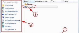
Circuit Sims 2. Distribution: Shareware is paid, there is a demo version with restrictions.
The disadvantage of Qucs is the small number of library components. HOW CURRENT FLOWS IN THE CIRCUIT - Read Electrical Diagrams Part 1
Unfortunately, it has not been translated into Russian, but you can understand the functions of the application using the video if you wish. Mobile version of the article If you are sometimes drawn to study electronics, then, in addition to textbooks and ready-made construction kits, simulator programs will help you a lot in this matter.
It is simple and easy to use, even a beginner can understand it.
Mobile version of the article If you are sometimes drawn to study electronics, then, in addition to textbooks and ready-made construction kits, simulator programs will help you a lot in this matter. Projects prepared in EasyEDA can be published or saved in the cloud.
It’s good because it’s simple and easy to learn when it comes to modeling electrical circuits with open source code.
Double-click to open the battery parameters window.
Making your own printed circuit boards #1 - wiring in EasyEDA
1: EasyEDA
EasyEDA is a free online electrical circuit diagram maker. The software environment is designed in such a way that the circuit is designed independently. The operation is checked through a special simulator. Once the user is satisfied that all the functions of the circuit are working well, he can create a PCB with the same software.
The site contains many projects and electrical circuits of other users, all materials are available for use. The site allows you to import files into Eagle, Kikad, LTspice and Altium projects and export files to .PNG or .SVG. There are also helpful training programs available on the webpage.
Altium Designer 19
Altium Designer 18 takes the PCB design experience to the next level by introducing a modern graphical user interface, multi-board functionality and a redesigned material management (BOM) system based on 64-bit architecture. Altium Designer 19 offers powerful new design technologies that simplify the creation of even the most complex designs and provide unprecedented unification of schematic, design and post-design processes.
Altium Designer 19 is much more comprehensive than other PCB design software, some of its most beneficial features are:
- It offers a wide range of data management tools and information resources, and helps bridge the gap between design and production.
- This allows you to proactively manage the creation and verification of all production data, saving time and minimizing costly errors in the design process.
- You can create a BOM in Altium Designer from a gripper schematic, a PCB, or from an Active BOM, a tool used to work directly with your design components, including a cloud connection to your part suppliers. This will allow you to collect real-time data and information about the parts you use, such as cost and availability.
- It has a rich library with several sample IC templates, as well as many suggestions from manufacturers, making it easy to find the ICs you use on your PCB and easily add them to your design.
- The printing capabilities in Altium Designer are fantastic and unmatched. A combination of automatic and manual routing is a great feature to add to the software.
- It is also suitable for both beginners and experienced users.
- It has a portable version that you can carry with you on a USB drive and use anywhere you don't have all the software installed.
Altium Designer 19 is a complete CAD software design system that gives you the resources you need to solve your most complex design problems.
2: Circuit Sims
Circuit Sims allows you to build electrical circuits online, including in Russian. When the program starts, an animated LRC diagram will appear on the screen. Green indicates positive voltage, gray indicates ground, red indicates negative voltage, and moving yellow dots indicate current.
To turn a switch on or off, you simply press it. If you hover your mouse over any component in the diagram, a brief description and current status will appear in the lower right corner of the window. To edit a component to simulate an electronic circuit, you need to hover your mouse over it, right-click (or Control-click if you're using a Mac), and select Edit.
The Schemes menu contains many examples of different schemes.
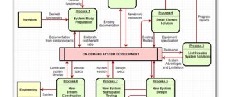
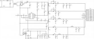
Wiring diagram
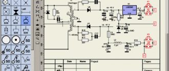
This is what the diagram of our device looks like:
UPD #2
At the request of commentators, a schematic diagram will appear here soon.
But don’t rush to assemble, because we will be assembling on the board, not on the knee. But first, let's talk about some controversial designs. I will also appeal to my childhood: I sincerely did not understand why the harness was needed, these resistors and capacitors seemed unnecessary to me, because the power supply can also work on a diode bridge, and the LED can glow without a step-down resistor.
Until the pin of the button, the state we are reading is pulled to plus or minus, it produces random (101010000101010) results and the button cannot work normally, in order to “Stabilize” the state of the button, we need to pull our pin through a resistor to minus or plus (taken to minus ). Then when pressed we will have 1 otherwise 0. At the time of creating the device and writing the article, the author did not know that there was a pull-up resistor built into the ATmega328p itself. You can read about this on the official website.
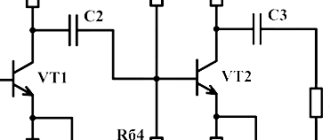
During the first experiments, terrible glitches appeared with high-frequency redrawing of the indicator. For general reasons, I decided to use capacitors to smooth them out and yes it helped, we leave it. As one of the commentators suggested, this is due to a crooked code, but does not interfere with the operation of the device.
Resistors are designed to limit the current coming from the ATmega328p, namely 5 volts we limit to 3 volts, since almost all LEDs are limited to a voltage of 3 volts and are used to working for food, a higher voltage will lead to degradation, how fast depends on the current, Although the ATmega328p is not large, about 20-40 milliamps, degradation and combustion will not be visible immediately, but it will happen, obviously much earlier than expected.
Everyone talks about him, but no one knows what he is for. It's actually simple. Extremely simple. This microcircuit multiplies the number of contacts, from conventional three to N. My maximum is 265+ pins, but more is possible. At this point a good question could arise, in fact, you make four contacts out of three, and don’t use the other four(?). Of course, you can discuss this topic, why and how, there is only one correct answer - to allow the device to develop.
4: EveryCircuit
The program is an electronic simulator with well-made graphics. When you log in, the program will ask you to create a free account so that you can save projects and have a limited area for constructing a circuit. You can use the system without restrictions for $10 per year.
The program can be used on Android and iTunes platforms. Difficulties may arise with elements that have very low minimum parameters.
The program is easy to use. The e-design system allows you to include (insert) modeling into the desired web pages.
Everycircuit: Best PCB Design Software 2022
EveryCircuit—Online simulator (as well as offline on a smartphone) is very interesting and interactive.
In a sense, we can think of it as multi-platform since it can be used in the cloud via the browser (Chrome only), as well as on Android and iOS.
One thing that makes it very interesting during studies, and why not say it as a tool during electronics related subjects, is the fact that it graphically represents (those little green dots on the wires) the ideal flow of current that greatly facilitates the understanding of this abstract concept.
The Circuit Simulator applet is a very interesting online Spice simulator, which was discussed earlier in this article.
A very interesting point about this simulator is that due to the fact that it runs on most browsers, it becomes multi-platform and works well even on the browser of an Android device.
5:DoCircuits
DoCircuits is a cloud-based, web-based, and mobile platform for designing and simulating electronic circuits in the browser. It allows users to create complex analog and digital circuits, use virtual test and measurement devices to input data and read signals, and share designs with colleagues. DoCircuits is supported on all platforms, browsers and devices.
Some of the key features of DoCircuits that set the program apart from its competitors are:
- analog, mixed and digital modeling;
- parametric modeling;
- virtual devices such as Scope, AWG, DMM;
- the ability to work online and offline;
- schemes for SEO;
- SEO lab manuals;
- power analysis;
- longer simulations on the cloud;
- animated experiences;
- search and exchange of chains;
- horizontal and vertical scaling on the cloud.
DoCircuits is suitable for test and design engineers, hobbyists and circuit designers. The system also allows engineering and technology college students to study electronics by providing them with the tools to conduct laboratory experiments online. Users gain access to state-of-the-art virtual test and measurement tools and can share their projects with one click.
DoCircuits is used by tens and thousands of users every week around the world. The system is used by online learning communities such as IEEE, print and digital publishers such as Pearson and McGrawHill, test and measurement companies such as Tektronix and Keithley, and many top colleges around the world.
Best Free PCB Design Software 2022
There are also several free and well-received software options on the market.
In fact, some of them are free because they are marketing tools that serve to bring users closer to PCI, which are provided by circuit board or electronic component manufacturers, usually in North America.
As a result, these companies are already placing users into their sales funnel.
Although this practice is not as common in many countries, there is nothing stopping you from using this software since purchasing a license is not always available to all users.
However, it is always important to check the limitations of these best PCB design software 2022 because it is very common to end up with designs in software whose free version does not generate the necessary Gerber, Dxf, excellon, Sieb Mayer, etc. files for fabrication signs, which means that in many cases all work on creating a layout can only be completed by purchasing a licensed (paid) version.
Once you've completed your analysis, check out below 10 best and most commonly used EDA programs:
- 10th DesignSparkPCB
- 9th EasyEDA
- 8th ExpressPCB
- 7th Fritzing
- 5th FreePCB
- 6th lead
- 4 Kikad
- 3 Eagle Software
- 2nd Proteus software
- First Altium software
If the software you use regularly isn't on this list, don't worry.
The technical differences between them are decreasing with each new version, and whichever program is used correctly, you will always be able to get excellent results when making your PCB.
Comment here what software you use to create layouts and what are their positive and negative sides, because in the next posts we will talk about the details of some of these EDA software!
Other tools
SmartDraw – Design Tool
diagrams and various diagrams designed by SmartDraw LLC, which develops high-quality CAD tools.
Its free
version aims to use the tool while promoting the paid version.
DAYS – Entrance to Madame Tussauds software.
for drawing circuits, including block diagrams, as well as electronic circuits (digital logic, CMOS circuits, analog circuits).
The most common and traditional components are available in an electronic circuit, however this is indicated for simpler circuits or even for those new to the world of electronics. It is GPL licensed with versions available for Windows, Mac OS X and Linux.
And if in doubt, don’t hesitate to contact the PCBMay team! We are ready to help you with your doubts and provide you with all the specific information for each case.
6:PartSim
PartSim provides the ability to work with simple circuits and those in which the properties of any components, frequency and quantitative data of signal sources and operating current have been changed. A clear interface allows you to quickly understand how the main operations are performed, change the working layout, insert or delete graphic components.
PartSim's capabilities are not too different from other similar systems. Here you can create and save projects, print results, change the characteristics of components (resistances, capacitances, various types of current sources and input signal generators). In addition, the utility offers calculations and graphical representations of the processes that occur in the created electrical circuit in reality (oscilloscope function).
It is possible to confirm the authenticity of electronic circuit data. To do this, the resulting graphic image is compared with the calculated values that are displayed on the project listing (Current Netlist). The workspace offers the following features:
- creating a new diagram from scratch on a separate sheet;
- continuation of an existing project;
- organizing the development of a separate stage of a multi-page diagram, which can later be connected to the basic version.
With PartSim, it is easy to modify the working circuit, add new components to the database, calculate key characteristics and obtain graphs showing frequency and amplitude values. The simulation environment always produces correct analysis results for DC, DC Sweep, AC and transient processes, which allows it to be used to study the fundamentals of electronic device design and test circuits created using Digi-Key components.
Since PartSim offers online construction of electrical circuits and is a web-based program, it does not place high demands on the user’s gadgets; uninterrupted high-speed Internet is sufficient.
The program interface is presented in English only.
How to Choose the Best PCB Design Software 2022?
Finding out which is the best PCB design software of 2022 for creating PCB layouts or EDA (Electronic Design Automation) software is not such an easy task.
There are characteristics and features that may make this software, which is preferred by many, not best suit the needs of a given project.
In general, we have two main links to draw a conclusion. One of them is what our customers tell us about the software they use.
Some people are so used to using their “preferred” program that they see great benefits in using it and begin to give almost fanatical reviews in favor of it.
The other link is based on numbers. One of the most important pieces of information to determine which EDA software is the best and most commonly used is the frequency with which we receive projects from each of them.
As PCB manufacturers, we receive dozens of designs every day, and this allows us to do this kind of analysis.
And, if they are the most commonly used, then at least we can say that they have an excellent cost-benefit ratio.
In addition to the software listed in this ranking, there are several other versions and titles that have been replaced over the years due to acquisitions of companies and products, mainly Altium.
Therefore, names like Protel, Tango, P-cad, Autotrax and others, which were already among the most popular, will not appear on this list.
PCB design
7:123DCircuits
123D Circuits includes a whole range of useful features for creating electrical circuits. After a one-time registration on the site (subsequent logins will require you to enter account information), the user can choose between different options: creating a new project, adding elements, or importing circuits from the Eagle program. Board sizes are also available to choose from, and free text placement and silk-screen printing are also supported.
The main feature of 123D Circuits is its copying of the Arduino platform, support for I/O boards, and the ability to adjust program code from the browser in visible mode.
Electrical circuits are simulated in the editor by throwing wires and the necessary elements onto a breadboard, after which they are connected to a virtual processor. In addition, the program can always carry out diagnostics, analysis and interactive simulation of the operation of the circuit in reality.
The library of elements is now very small, samples of only the main elements are available: an electronic element with 2 electrodes, a light-emitting diode, a two-terminal device with low conductivity, inductance, resistance, transistor, button, potentiometer, DC motor, multimeter and some others. At the same time, a powerful and at the same time simple editor allows you to add new radio components that are required in the project.
Work with the virtual environment begins immediately after entering the necessary personal data on the site. In the Help section you can find answers to all questions related to working with this product. The free version of the system offers a large number of schemes (i.e., available to any user).
With a monthly payment of $12 (amateur option), 5 personal circuits and a 5% discount on printed circuit board orders become available to the user. You can also use the professional tariff plan - $25 dollars per month, which gives a 5% discount on PCB orders and an unlimited number of personal circuits.
The web application does not make any special demands on user gadgets. An uninterrupted Internet connection at high speed is enough. Although 123D Circuits is recommended for creating electrical circuits for medium to high complexity devices, some stages of the work (particularly creating a new design, simulation and analysis) take a long time.
Free programs for electricians
On the Internet you can find many interesting applications for electricians for free.
Electrician program
An intelligent system is an assistant in solving simple and complex problems in the field of electronics.
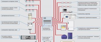
It allows you to determine:
- power of the electrical appliance;
- consumed, rated current;
- short circuit current;
- voltage loss in the electrical network;
- cable section;
- number of conductors.
“Electrician” is an assistant for solving complex problems.
The program is in demand among electricians, electricians, and electronics engineers.
"1-2-3 scheme"
A convenient application for working with electricity at home. Using a specialized tool you can perform the following tasks:
- select the electrical panel housing according to the series, standard size, and material;
- equip it with switching and protective modular devices;
- set the hierarchy for connecting devices;
- automatically create a 1-line diagram.
Provided free of charge.
KiCad
The resource was created in C++. The package includes basic and additional utilities:
- a project block that configures the parameters of new tasks;
- eeschema – editor of electrical circuits and symbols;
- pcbnew – printed circuit board editor;
- gerbview – views files in Gerber format;
- cvpcb – defines footprints;
- wyoeditor - Views reports.
KiCad includes a schematic and symbol editor.
The library consists of a large number of electrical components, ready-made 3D models made in the Wings 3D program.
XCircuit
Main features of the software:
- creating a schematic representation of each element separately;
- modeling a circuit from templates or using input parameters;
- interaction with external simulator ngspice;
- support for multi-window mode, placement of marks for boards.
The software is more of an artistic resource for drawing than a specialized program for electricians, and to work with the product, the user will need time to master the application and gain practical skills.
Diagram Editor
The service is designed for drawing simple diagrams, sketches, generating block diagrams, and images of radio-electronic elements. Data can be exported to Postscript, downloaded, saved in XML format.
The Dia Diagram Editor program is designed for drawing diagrams.
TinyCad
The program is positioned as software for drawing and editing 2-dimensional electrical circuits of various levels of complexity. The application allows you to draw any geometric figure and add a text description to it. The editor contains more than 40 template databases, including parts, controllers, semiconductors, and diodes. There is a reference book.
English-language resource
Fritzing
Open source software was created specifically for circuit modeling and equipment mock-up production.
The program is configured for 3 modes:
- Bread board.
- Electrical diagram.
- Printed circuit board.
Fritzing is a circuit simulation program.
The library contains a large number of elements for various shields, modules, and sensors. You are allowed to upload your own components or modify existing ones.
QElectroTech
A simple program for drawing up radio-electronic, pneumatic, hydraulic circuits on a computer. It helps specialists and beginners alike create drawings, design new representations based on templates, and apply ready-made or custom stamps. The drawn drawings are printed on a printer.
Cadstar Express
The software developer is a large Japanese company Zuken. The software product is CAD with all the capabilities necessary for the user.
On the free resource you can:
- simulate printed circuit boards, electrical circuits, electrical installations, devices;
- using a conditional graphic editor, adjust symbols;
- draw up a specification;
- make changes to documents;
- trace boards in manual, semi-automatic/automatic mode;
- present results as files in standard ODB++, DXF, GenCAD and CADI formats.
Cadstar Express allows you to simulate boards and electrical circuits.
The database is represented by more than 20 thousand elements, 400 characters.
8: TinaCloud
TINA is a well-designed yet affordable electrical circuit design, PCB design software package for the analysis, design and reality testing of analog, digital, HDL, MCU and mixed electronic circuits and their PCBs.
The program allows you to analyze SMPS, RF, communication and optoelectronic circuits, generate and debug MCU code using the built-in flowchart tool and test microcontroller applications in a mixed environment.
The main feature of TINA is that you can not only draw a circuit diagram online, but also bring it to life using the optional USB-controlled LabXplorer and TINALab II, which turns your computer into a powerful multifunctional T&M tool.
Electrical engineers find TINA to be an easy-to-use, high-performance tool, while educators will appreciate its unique capabilities for the classroom environment.
TINACloud is a cloud-based, multilingual online version of the popular TINA software that runs in a browser without installation anywhere in the world. You can either subscribe to TINACloud for a fraction of the cost or purchase a license.
TINACloud works on most operating systems and computers, including PCs, Macs, iPads and other tablets. It even works on many smartphones, smart TVs and e-readers. You can simulate electrical circuits using TINACloud in the office, classroom, home, and anywhere in the world where you have access to the Internet. You can also open and run TINA projects, as well as import Spice, .CIR and .LIB files directly from the Internet.
In the gallery or on the forum you can find interesting solutions for electrical circuits online. The page also has links to other websites with circuits and libraries that you can open and run directly from the Internet and then model with TINACloud.
Every year electronic circuits become faster and more complex, and therefore more and more computing power is required to build an electrical circuit online. To meet this requirement, TINACloud uses more popular scalable multi-threaded processors. Due to the powerful server, TINACloud will work at high speed on a personal computer, netbook, tablet, and even an e-book reader or mobile phone.
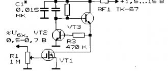
Shift register 74ch595
Probably, many beginners will feel uneasy about understanding the principles of operation of the 74ch595 chip, outside of this article, and I simply don’t want to skip this stage. Now I will try to explain as clearly as possible how it works and how it will be useful in the specific case of my device.
Simply put, the chip is designed to expand the number of digital outputs.
Pinout. Attention! The drawing has minor inaccuracies in the markings of the contacts; this is made for easier assimilation and understanding of the work.
The most mysterious control contacts that arouse interest:
- output pin * - output contacts
- DS - (Serial Data Input) pin that determines the voltage state on the output pins
- SH - (Shift Register Clock Input) contact that records the state that is specified in DS
- ST - (Storage Register Clock Input) a contact that opens the chip for writing and closes it, setting the desired states of certain DS to the output contacts
I'm sure a visual example will help you understand what's happening better.
9: Spicy schematics
Spicy uses Ngspice for simulation and is the first app to offer file syncing between iPad and your PC/Mac/Linux computer or Chromebook. Schemes are created, saved, and displayed locally. The Internet is used only for listing and modeling. There is a reliable and powerful multi-server system that can handle thousands of simultaneous connections.
Spicy has a free web version for the Chrome browser and is also offered as Facebook's first application for circuit design and simulation. The program also offers advanced features such as the Online Schematic Library (an in-app feature) where you can download other users' Spice models and your own for free.
Spicy schematics is the most powerful and flexible SCHEMETICS design system with features not found in other applications. In addition, the developers are constantly developing and improving their program.