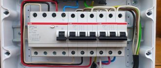
Assembling an electrical distribution panel requires clear sequence, accuracy and compliance with requirements and calculations. It is possible to install it in a house or apartment on your own. To do this, you need to have basic knowledge of electrical engineering and a desire to study in more depth all the features of electrical installation.
Switchboard elements
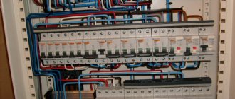
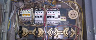
The distribution panel for an apartment or house consists of the following main elements:
| Metal or plastic shield (built-in or mounted). | |
| DIN rails on which the automation is mounted. | |
| Distribution busbars and terminal blocks. | |
| Electric energy meter. | |
| Circuit breakers. | |
| Residual current devices (RCDs). | |
| Differential machines. | |
| Wires connecting all elements. |
In each specific case, components selected taking into account the requirements and calculations should be used. Any additional elements will increase the cost of assembly. Therefore, avoid overloaded and unreasonable schemes. As an addition, familiarize yourself with the methodology for selecting automatic machines and RCDs.
Recommendations for assembling an electrical panel
Having selected the distribution board required by design, you can proceed to the stage of design and selection of appropriate automation. In this case, you should take into account and continue to adhere to the following recommendations:
- The panel must be filled in accordance with the design documentation. Let's say there are ten machines, a counter and eight RCDs. In this case, the characteristics of the purchased electrical panel must allow it to accommodate this number of blocks. A small reserve is welcome.
- In further orientation according to the diagram, marking groups of elements with tags will help.
- Adhere to the color unity of the wire cores. For phase conductors, the preferred colors are black, brown and gray. The ground conductor is usually yellow-green in color. Zero (neutral) has a blue or cyan color.
- Connect one wire to each terminal of the terminal block. Installing several wires in one socket will worsen the fixation and over time the contact may disappear.
- To make it easier to connect the automation, you can use special tires (combs).
Distribution board diagram
There are many configurations of electrical panel circuits. They differ in the place of application (for a house or apartment), the presence of a grounding circuit (grounding, grounding or absence), the number of phases (single-phase circuit 220 volts or three-phase circuit 380 volts) and other parameters. We will not go deeper into this issue. Let's consider only a simple single-phase circuit with grounding and highlight the main features of the assembly.
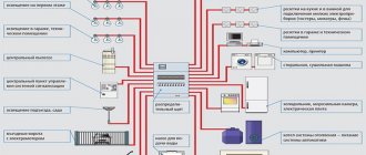
Below is a diagram showing the main components of a switchboard.
|
A diagram developed taking into account a specific destination will simplify orientation in an extensive electrical wiring network, organize energy consumers (household electrical appliances) and show the purpose of each involved automation element in the electrical panel.
The uniform rules for any distribution board schemes are:
- Availability of an introductory machine in front of the counter. With its help, it will be possible to turn off all phases of the supply voltage to ensure safe work on replacing the meter.
- On electric stoves, ovens, air conditioners and other household appliances with high power, it is advisable to install separate machines in conjunction with an RCD. Or arrange these consumers taking into account their total power consumption.
- For rooms with high humidity, it is necessary to install additional RCDs or differential circuit breakers.
- When laying out the electrical panel, it is necessary to coordinate the characteristics of the protection devices installed in series so that in the event of an accident, only that power line or part of the circuit where the problem occurred is switched off (selectivity principle).
Programs for completing and designing electrical panels
cineman wrote: Even in apartments/cottages, conversations can drag on for years before editing begins. A customer can disappear for years in search of cheap labor, and then emerge screaming: “We start tomorrow.” And it is inconvenient to store information about such swimmers in pencil in a notebook.
For such cases, I have a special folder on my disk for each object - data from the customer, my calculations, developments, etc. are stored there. It is not at all necessary to store all this in the form of a working file of one program.
megrad wrote: Cool, but after creating the project you need to customize it for specific equipment. Hager has such a program, but it’s very bad. It seems that Schneider has it, but I haven’t come across it. In an office like the ABB distributor, they sketched out an installation project for the panel in 15 minutes. I only named the denominations. The program itself added all the filling. Only I found Legrand, but not ABB. Yes, plus you need to update the database
Here you have to choose.
You will not be able to provide third-party equipment in software like Abb / Schneider. Yes, the same Meander or a competitor’s module.
In eplan and autocad electrical everything is possible, but before that it is necessary to carry out quite a significant amount of work on creating the element base, templates, etc. And is this really necessary for such small volumes? I think not.
In addition, there is another criterion that is constantly forgotten in our country - the cost of software. Which in the second case will amount to hundreds of thousands of rubles.
serj12 wrote: I’m embarrassed to ask - Can you help with a simple cottage?! I just need to assemble the input. Everything is simple there - surge protection, manual input of the reserve, 3x10 kVA stub and so on little things: swimming pool, three floors, street with ponds and pumps for circulation , and other small things - a 75 kW gas boiler, a water treatment unit, Hunter watering and some stupid swing gates... Really sheer nonsense
Do not Cry. Your cottage with a swimming pool is really a good project for a private craftsman and has a fairly impressive amount of work in terms of work. But I don’t agree with you that compiling a shield there requires SPECIALIZED programs. Excel is enough for you.
The company where I work is engaged in the creation of distributed control systems for oil refineries/petrochemical plants. The average project, which, mind you, is carried out by one person, at least in terms of specifications, is approximately 60-80 Rittal cabinets, filled with all kinds of equipment, including a modular unit from the same Schneider.
So, until recently (while the company switched to Eplan, having invested a lot of effort and money into it), everyone worked in a combination of AutoCAD + Excel. Moreover, Excel was used to draw up the specifications. AutoCAD is for layout drawings, but they can also be drawn schematically in Excel. The specification was drawn up taking into account tires, plugs, as well as markings.
And nothing, everything was done perfectly. Your humble servant has completed more than one project like this alone.
I don’t see any reason why you can’t handle your cottage in Excel.
cineman wrote:
serj12 wrote: I gave up and do visualization in Excel
I tried to draw modules in AutoCAD, but I couldn’t draw the black lever of the machine properly. Normally printed every other time. Either it’s normal, or it’s a fat blob instead of a lever. Line weight was included in each case.
Send your file to my email.
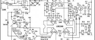
Program 123 schema, download
Program 123 diagram allows you to select the design of an electrical panel in accordance with the requirements, equip it with automatic protective equipment, set a hierarchy for connecting modular devices and automatically generate a single-line diagram of the panel.
| We start the installation of the program. Select the installation location and other parameters. We are waiting for the installation to complete. | |
| After installation, launch the program. In the first dialog box, you need to specify the initial parameters: from an empty panel or from a standard installation. | |
| By selecting the “from empty shield” option, the following dialog box will appear. Here you select the appropriate type of electrical panel. | |
| Next, the configuration of the selected distribution board is specified. | |
| After completing all the preparatory steps, a program window with a diagram of the shield will open on the screen. The 123 schema interface is simple and intuitive. Having selected the appropriate automation, use the mouse to move it to the desired location on the shield. Once the panel is fully configured, you can view the diagram, specification and other useful information regarding the selected distribution panel. |
is included with the 123 Schema program . This tool allows you to automatically create beautiful and neat labels for marking consumer groups in electrical panels.
Paid programs - assistants
Licensed software from domestic and foreign developers is provided on a paid basis.
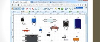
Splan
Splan is a program for designing electrical circuits by a radio amateur or electrician. The official application is created in English. The user can easily understand the settings without downloading a Russified utility, although there are Russian versions with an updated database of radio elements.
Splan is needed for designing electrical circuits.
The package includes a graphic editor, a text module, and libraries with ready-made electrical components. The library block can be expanded - supplemented with your own templates.
In addition, the system has functions such as:
- automatic numbering;
- grouping elements;
- drawing components at an angle;
- rotation of the template;
- inserting a picture;
- export to jpg, bmp formats.
A distinctive advantage is the function of printing large formats on a simple printer with the entire drawing divided into A4 sheets.
AutoCad
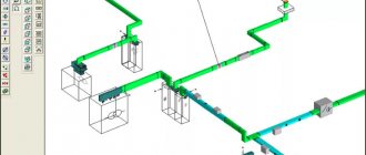
The world leader in the development and supply of software for designing objects, manufacturing mechanical engineering, welding structures, and electrical equipment is the Autodesk company, founded in California, USA. Its main commercial product, known among engineers, is the AutoCad program. The automated system is capable of creating 2- and 3-dimensional drawings.
AutoCad is an automated system for creating drawings.
Based on it, the AutoCad Electrical add-on was released - an extended version for electrical engineers who are involved in electronic modeling of products. In addition to the main construction functions, the application contains tools for generating graphic images, designing 2D drawings of the layout of mounting panels, cabinets, and automatically generating reports.
The complex has programmable logic controllers (PLC), the functions of which greatly increase productivity and provide accurate images of electrical and other circuits. The PLC input/output library contains more than 3 thousand products from different manufacturers.
As of 2022, the software is no longer available as a separate product. The add-on is included in the complete AutoCad package.
NanoCad
CAD was developed on the basis of Russian standards and is intended for the design of power electrical equipment, external/internal electric lighting. The special Open Bim tool allows you to integrate the created electrical network into the model of the designed object on any Bim platform. The process is carried out thanks to export to IFC standard exchange files.
NanoCad is intended for the design of electrical equipment.
NanoCad "Electro" is capable of performing the following calculations:
- Lighting measurements (number of lamps in the room) using 2 methods:
- point;
- using the utilization rate.
- Electrical parameters:
- electrical loads;
- 1-, 2-, 3-phase short circuit currents;
- leakage currents through insulating material;
- wires for non-ignition;
- voltage drop.
The program contains a free, ready-made database of electrical equipment from different manufacturers that collaborate with intellectual product developers as part of partnerships.
Eagle
A paid package has been released in English to help electricians. There are localizers on the Internet, but they do not guarantee high-quality translation or correct operation of the application.
Eagle allows you to create electrical diagrams.
Using the software, you can draw up electrical diagrams and trace the board.
Main parts of the program:
- Schematic Module – graphic module. Allows you to create images of electrical circuits using standard components.
- Layout Editor – layout editor. Helps the user to make manual PCB drawings.
- Autorouter – automatic router. Defines the location of conductors on a printed circuit board.
Beginners can install a free version of the program with minor restrictions.
"Elf"
The software has a rather difficult to understand interface.
Thanks to the distribution, users can:
- design interior lighting down to the smallest detail;
- draw up specifications for wiring, electrical installations, objects;
- create documents;
- calculate loads on buildings;
- perform analytical and geometric calculations;
- select switches, lamps, cables, wires according to parameters;
- make drawings when planning electrical circuits.
The Elf program has a complex interface.
The software was created by IT for Windows OS and is presented in Russian.
Microsoft Visio
The resource developer is Microsoft. The application for electricians is included in the basic office software package. The system's tools are capable of producing simple radio circuits. In the menu, the user can find a library of templates and use ready-made sketches of elements and nodes. You can upload your own structural drawings from a computer or electrical components from additional databases downloaded from the Internet.
The add-on for electricians is compatible with Word, which allows you to draw pictures and sign them.
Dip Trace
Commercial product – high-quality service for the development of complex multi-level electronic boards and electrical circuits from the Ukrainian company. The program has an intuitive interface, works without errors, contains a database of 140 thousand components, 15.2 thousand 3D models of housings, and finished structures.
Using the graphical tools "Package Editor", "Component Editor" and "Spatial Modeling", the user can easily create his own board layout.
Dip Trace is an electronic board development service.
The developer offers beginners a free trial or 30-day demo version of the program for Win32, Win64, MacOS.
Eplan Electric
Eplan Electric P8 is an updated specialized system for engineering. CAD is an additional modular complex of electrical engineering design, automatic creation of connection diagrams, working and design documentation. The founder of the program is the leading supplier of IT products Eplan Software & Service GmbH & Co. KG (Germany).
Software features:
- Calculation of electrical parameters.
- Formation of an electrical circuit and wiring.
- Saving up to 26 scheme options for each presentation.
- Macro project management.
- Moving components using drag-and-drop technology.
- Formation of specifications for terminal blocks, cables, consumables.
- Data analysis.
- Generating breakpoint cross-references.
- Printout of the drawing.
Eplan Electric is a complex of electrical engineering design.
The company provides a chance for everyone to sign up for a practical seminar, take a course or train online.
Target 3001
Thanks to the application, an electrician can draw an electrical circuit, create a printed circuit board model, and design the front panels of front devices.
The software interface is clear and the settings are easy to understand. The basic operations are similar to the functions of the Splan program.
Main distinctive features:
- Asic Designer is a block that allows you to create the design of integrated circuits.
- Simulation of electrical circuits using direct and alternating current using the PSPice simulator.
- Auto positioning.
- Built-in autorouters.
- Vector graphics.
- Reading raster files.
- Packaging BGAs, COB.
Target 3001 allows you to draw an electrical circuit.
To get acquainted with the application, you can install a free limited demo version of 250 pins, 2 layers, 30 signals.
Micro-Cap
CAD was developed by Spectrum Software (USA), which ceased to exist in 2022. Therefore, the program created for analog/digital modeling of electrical circuits with a visual editor is now freely available in English. It can be downloaded for free.
The program has a wide range of capabilities:
- Drawing up circuit equations.
- Calculation of indicators.
- Designing an electrical circuit in a graphic editor.
- Library of electronic components.
- Replenishing the database with elements using the Shape Editor module.
- Analysis of transfer parameters, DC sensitivity, transient processes.
Micro-Cap is a program with a visual editor.
Micro-Cap is a popular application among radio amateurs, novice DIYers, professional electricians, students, and microelectronics university teachers.
TurboCad
A set of special tools is capable of solving an engineering or electrical task. The program is similar to construction AutoCad, but there are differences in its favor:
- High-quality visualization of a 3-dimensional model.
- Large selection of architectural and mechanical tools.
- Precise design of objects.
- Customizing the interface for the user.
Due to the expanded functionality of CAD software for drawing, it is suitable for builders, mechanics, and designers.
Designer Schematic
An intellectual resource for electricians – a joint development of American companies Digi-Key Corporation and Mentor Graphics Corporation. The software is at the testing stage. Therefore, users are offered to download the beta version in English.
Designer Schematic is a resource for electricians.
The application allows you to work with diagrams of different sizes and any level of complexity. A detailed description of the options is displayed in pop-up tabs - tooltips. The graphic editor has functions approaching those of mechanical CAD systems. The library was created on the basis of the world's largest supplier of electronic products, Digi-Key.