Where is the 220 to 24 volt transformer used? In fact, devices of this type are necessary for various electrical appliances that can operate on a 24 V network. To do this, direct current from a 220 V outlet must be converted. Transformers are selected for this purpose.
24 V equipment includes compressors, distributors and also electric motors. Also, many drives operate from a network with a voltage of 220 V. In this case, it is important to note that transformers are produced in different capacities. Today, even 20 W models are available on the market. However, there are very powerful modifications that are actively used in production.
The device of a simple transformer
The main element of the transformer is the relay. The coils themselves are installed with different windings. Magnetic cores are available with cores. In terms of current conductivity, they differ quite significantly. It is also important to mention that some modifications include special extenders. In this case, much depends on the operating frequency parameter.
Insulators in transformers are designed to protect the core from overloads. To rectify direct current, transceivers are installed in devices. They are produced in orthogonal and tuning types.
Downgrade modifications
A step-down transformer from 220 to 24 volts is often found with a power of 100 watts or more. Devices of this type are used, as a rule, for electric drives. Many models have magnetic cores with relays with strip cores. It is also important to note that the windings in 3 kW devices are installed concentrically. However, modifications with three-layer analogues are available on the market. There are two total outputs for step-down devices.
Some modifications are available with terminals. A step-down transformer 220 to 24 volts weighs no more than 5 kg. The models differ quite significantly in terms of current conductivity. In this case, the type of transceiver must be taken into account. Domestic transformers are mainly sold with orthogonal analogues. However, foreign companies prefer trimmed transceivers. The current overload indicator for models is on average 5.5 A. Some devices are available with switches for phase adjustment.
Is it possible to connect lead batteries of different capacities in parallel?
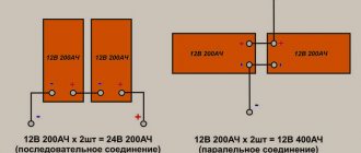
For parallel-connected lead acid batteries, there is no danger of different voltages appearing at the battery terminals. The voltages on all parallel-connected batteries are the same due to the very nature of the connection. This means that batteries connected in parallel cannot “run apart” - they will be discharged or charged synchronously.
But lead-acid batteries have limitations not only on maximum and minimum voltage, but also on current. For example, for the CSB GP 1272 (GP1272) battery, the manufacturer has set the following current limits.
The maximum discharge current should not exceed 100 A for batteries with terminals 3/16″ (4.75 mm) wide and 130 A for batteries with terminals 1/4″ (6.35 mm) - 130 A (18C). The flow of such a large current through a battery with a capacity of only 7.2 A*hour is also limited in time: no more than 5 s. It is clear why the discharge current is limited - the battery terminals cannot reliably transfer more current (although the battery itself probably could).
If we look at the technical characteristics of batteries from different manufacturers (although not all indicate the maximum permissible current), we will see a rather motley picture. For stationary (industrial) lead-acid batteries, the maximum current is limited to a value that numerically (in amperes) ranges from 5 to 25 battery capacities (in A*hour). Some manufacturers also indicate the short-circuit current (sometimes with a time limit of 0.1 s) - it ranges from 15 to 70 battery capacities (15C. 70C). Summarizing these data, we can say that a lead battery can be safely discharged with very high currents, up to tens of C, and the shorter the discharge time, the greater the permissible current.
The manufacturer of the CSB GP 1272 (GP1272) does not provide a strict limitation on the maximum charging current; it only recommends limiting the maximum current of the charger to 2.16 A (this is numerically equal to 30% of the battery capacity - 0.3C). This limitation is definitely not related to the capabilities of the conductors (the terminals and grid of battery plates) - the conductors of this battery, as we already know, can transmit 50 times more current. Then what is the reason for this limitation?
Toroidal models
The toroidal transformer 220 to 24 volts differs in that it contains a comparator. Due to the specified element, the clock frequency from the network is changed. It is also important to mention that many devices are equipped with zener diodes. The magnetic cores in the devices are installed as usual.
The windings for transformers themselves are of the concentric type. These devices are most often used for low-power engines. They are also suitable for many types of compressors. As a rule, there are no regulators in devices. Insulators are used of the composite type. On average, the current conductivity parameter of the models does not exceed 50 µS. In turn, devices with a power of 80 W can withstand an overload of 3 A.
Integral stabilizer and zener diode
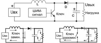
Build a stable source of non-standard voltage using three-terminal voltage stabilizers. Schemes to the studio!
What do we see as a result? We see a voltage stabilizer and a zener diode connected to the middle terminal of the stabilizer. XX are the last two digits written on the stabilizer. There may be numbers 05, 09, 12, 15, 18, 24. There may already be even more than 24. I don’t know, I won’t lie. These last two digits tell us the voltage that the stabilizer will produce according to the classic connection scheme:
Here, the 7805 stabilizer gives us 5 Volts at the output according to this scheme. 7812 will produce 12 Volts, 7815 - 15 Volts. You can read more about stabilizers here.
U of the zener diode is the stabilization voltage on the zener diode. If we take a zener diode with a stabilization voltage of 3 Volts and a voltage regulator 7805, then the output will be 8 Volts. 8 Volts is already a non-standard voltage range ;-). It turns out that by choosing the right stabilizer and the right zener diode, you can easily get a very stable voltage from a non-standard range of voltages ;-).
Let's look at all this with an example. Since I simply measure the voltage at the terminals of the stabilizer, I do not use capacitors. If I were powering the load, then I would also use capacitors. Our guinea pig is the 7805 stabilizer. We supply 9 Volts from the bulldozer to the input of this stabilizer:
Therefore, the output will be 5 Volts, after all, the stabilizer is 7805.
Now we take a zener diode at Ustabilization = 2.4 Volts and insert it according to this circuit, it is possible without capacitors, after all, we are just measuring the voltage.
Oops, 7.3 Volts! 5+2.4 Volts. Works! Since my zener diodes are not high-precision (precision), the voltage of the zener diode may differ slightly from the nameplate (voltage declared by the manufacturer). Well, I think it's no problem. 0.1 Volt will not make a difference for us. As I already said, in this way you can select any value out of the ordinary.
Oil models
The 220 12–24 volt oil transformer is equipped with a special heat exchanger. Channels are used directly for coolant. The cores in many modifications are of the tape type. Three-layer windings are most often used. Relays deserve special attention. They are installed with different conductivity. On average, for oil configurations this parameter fluctuates around 60 µS.
Coils in devices are installed with magnetic cores. There are two direct terminals for connecting equipment. Some configurations are produced with terminals. Oil-based devices are ideal for electric drives. Transceivers in all models are installed only of the orthogonal type.
Why connect batteries to form a battery?
In any electrical systems or devices there are ohmic losses: part of the electrical energy is converted into heat without producing useful work. The higher the voltage of the electrical system, the lower (with the same power) the current, the lower the ohmic losses and the lower the price of the system. Those. It is beneficial to have high voltage electrical systems. Moreover, the greater the power of the system, the greater the gain of the high-voltage system compared to the low-voltage one. Therefore, small UPS (several hundred VA) usually have one 12-volt battery (this is cheaper), a UPS with a voltage of several kVA uses a battery with a voltage of tens of volts, and in powerful UPS with a voltage of tens of kilowatts, the battery voltage can exceed 500 V .
Therefore, the purpose of using batteries with series connection of batteries is to reduce losses and increase efficiency.
And sometimes the capacity of one battery is not enough, and you need to increase the capacity. Sometimes it is more convenient not to replace a battery with a larger capacity, but to place another one of the same battery in parallel, so that the total battery capacity of the battery doubles.
For example, to increase the operating time of a high-quality Eaton Powerware 9130 UPS from a battery, one or more of the same batteries are connected in parallel to the existing battery.
How to make a device with your own hands?
Making a 220 to 24 volt transformer with your own hands is quite difficult. First of all, for a step-down modification you will need a large coil with good current conductivity. In order to ensure stable operating frequency, the winding must be of concentric type. Directly to connect equipment, terminals are used, which are simply conductors.
In this case, conventional expanders are installed. They can be used from any broken transformer. If we consider modifications with switches, then we will have to make a separate stand for them. To prevent failures from occurring frequently, insulators are used. Nowadays, composite analogues are considered to be the most reliable.
80 W model
A 220 to 24 volt DC 80 watt transformer is most suitable for conventional compressors. Models of this type are quite rare in production. Their energy consumption is insignificant, but the power for a normal electric drive is definitely not enough. Magnetic cores in devices are usually used with a low-voltage winding.
In this case, the cores are of the stamped type. If we consider configurations with high current conductivity, then they have special comparators. However, most often conventional bends are installed. There are also models with stabilizers. In this case, the overload current parameter averages 3.5 A. Switches on 80 W models are never used.
Is it possible to connect lead batteries of different capacities in series?
And it is known that the internal resistance of batteries manufactured using the same technology is approximately inversely proportional to the battery capacity. Therefore, when current flows through a series battery, lead batteries of different capacities will have different voltages. Is this dangerous for individual batteries and for the battery as a whole? Let us consider separately the discharge and charging modes of lead batteries.
Suppose we are charging a series battery consisting of seven 12-volt lead-acid batteries with a capacity of 10 Ah and one 12-volt lead-acid battery with a capacity of 8 Ah. At the beginning, all batteries are discharged. The charger implements an IU charging algorithm with an initial current of 1 A and a final voltage of 110 V (13.8 V on average per battery).
According to the manufacturer, when charging batteries with direct current, the voltage on the battery changes in accordance with the graph on the right. At the beginning of the charging process, the charger maintains a current of 1 A, and the total voltage on the battery is the sum of the voltages on individual batteries; the voltage for each battery can be determined by its charging characteristics (a graph of battery voltage versus time, which is given by the manufacturer in its technical characteristics ). At the beginning of charging, an 8 A*h lead battery will have about 12.3 V, and all 10 A*h batteries will have about 12 V each. Starting charging is absolutely safe for all 8 batteries.
100 W device
A 220 to 24 volt (100W) transformer can be used for electric drives. Many modifications are equipped with reliable protection systems. Most often, manufacturers indicate the IP20 marking. All this suggests that the model’s grounding system is used with composite insulators. If we talk about magnetic cores, they are used with a secondary winding.
Quite often, cores are of the sheet type. However, there are many stamped analogues on the market. In terms of quality, they are not much inferior to sheet cores. Current conductivity for 100 W configurations averages 70 µS. If we talk about overloads, then a lot in this situation depends on the manufacturer. Devices with transceivers are rare. However, 100 W transformers with stabilizers are in great demand.
Transformer 120 W
Transformer 220 to 24 volts 120 W is suitable for electric motors of different power. The cores are installed in sheet type in many configurations. Magnetic cores, in turn, are available with a high-voltage winding. The devices have two pins as standard. Some models are produced with terminals for connection to equipment. There are different cooling systems today. However, most often we are talking about a normal decrease in temperature due to air circulation.
Coils in transformers are often mounted on support rings. In some cases, models have extenders. Switches are also used in transformers. Transceivers are used of both orthogonal and tuning types. In this case, much depends on the operating frequency of the network. If it does not exceed 40 Hz, then you can safely use orthogonal transceivers. Otherwise, only trim components are suitable for normal operation of the device. Stabilizers are used quite rarely.
24 Volt models
ROLSEN RCR-102B24
The device is manufactured by a Chinese company, has a supply voltage of 24 Volts and a standard radio size of 1 DIN. Information is displayed on a small monochrome screen, and the radio is controlled using buttons on the panel; there is a USB port on the front side.
The Rolsen 24 Volt radio has a maximum output power of 4X45 W, supports playback of MP3 music files from a flash drive and SD and MMC memory cards. The GU allows you to listen to FM radio stations, with the ability to store up to 18 stations in memory. According to positive user reviews, excellent sound quality is noted for a minimal price, an excellent choice for those who are looking for a radio and nothing more.
URAL (URAL) RU/MP3-219SA (12-24V)
The head unit was developed and manufactured by the Ural company specifically for trucks, the radio supply voltage is 24 Volts. Device size 178X50mm. Information is displayed on a two-color screen; the head unit is controlled using buttons on the front panel of the radio. The Ural 24 Volt radio has a maximum output power of 4x50 W, supports playback of MP3 music files from a flash drive and SD and MMC memory cards, the USB port is located on the front panel of the radio.
Single band devices
A single-range 220 to 24 volt transformer is capable of operating in a network with a frequency below 45 Hz. In this case, comparators are installed in all models. Due to them, the current conductivity indicator can be easily stabilized. Transceivers are mostly orthogonal. The insulators themselves are specified for composite models. Magnetic cores for current conversion are used on the high-voltage winding. In this case, the coils must have support rings. Single-range transformers do not have heat exchangers.
Multi-band modifications
A multi-range transformer 220 to 24 volts can be used quite easily from a network with a frequency of over 45 Hz. Jumps in the system rarely occur in models. Due to this, electrical equipment works better, and energy consumption is not very high. Comparators in such modifications are of the two-pole type.
The current conductivity of the models exceeds 80 µS. In turn, the overload parameter is usually 5.5 A. Insulators in this case are installed on the taps. Switches are used to avoid various electromagnetic faults. Heat exchangers in structures are used in various capacities. To strengthen them, supports and slats are used. Many models have a liquid cooling system. Magnetic cores are used with high-voltage windings.
Where is it used?
Inverters are most often used in emergency or backup power supply systems. With their help, AC power supplies are created, designed to connect devices and equipment operating from 220 volts. These include kitchen appliances, televisions, and various power tools.
In the event of a power outage, a 24V-220V inverter is capable of providing electricity to a cottage or country house for several hours. If necessary, the converter can be powered by a car battery. In this case, specialists involved in construction and repair can drive up to any point and connect the power tool in the absence of the main network voltage. Mobile inverters have proven themselves very well during travel, as well as hunting and fishing.
A backup power supply system using inverters, used in private homes, ensures complete independence from centralized networks. During blackout periods, power is supplied from batteries, the energy of which is converted using an inverter. When the central network starts working again, the inverter automatically charges the batteries at this time.
When comparing voltage converters with generator sets, it becomes clear that inverter systems have significant advantages. First of all, it is silent operation, there is no need to purchase fuels and lubricants, consumables and spare parts. There are no moving parts, so the converters are considered more reliable and require virtually no periodic maintenance.