How does three-phase voltage differ from single-phase
Modern residential buildings and the vast majority of industrial enterprises are connected to the network using a three-phase, four-wire power supply circuit.
According to the new standards, to improve consumer safety, a fifth grounding conductor is added, which is used only in an emergency and does not serve to supply voltage, but to protect against electric shock.
All conductors in a three-phase network have their own designation:
In such a power supply circuit there are two voltage values:
- Linear. It is measured between two linear wires and reaches 380 V. At transformer substations and distribution centers it is designated 0.4 kV. It requires four conductors - three supply wires L1, L2, L3 and neutral N, through which the equalizing current flows.
- Phase. It is measured between one of the linear conductors and the neutral. It is 220 V. This is what is necessary for most household electrical appliances and is supplied to the apartment via two wires - phase L and neutral N.
Single-phase voltage is a special case of three-phase voltage and is obtained by connecting the consumer to the phase and neutral wires. Apartment buildings and garage cooperatives are connected to a four-wire, three-phase network (with a five-wire PE grounding wire), and only two wires are supplied to individual consumers.
For private houses and cottages, this separation is carried out on power lines, from which two or three wires extend. The third conductor in household electrical wiring is grounding (protective) and is not involved in powering electrical appliances.
| Important! If the neutral conductor breaks, the voltage in the outlet can fluctuate from 0 to 380 V, which has a detrimental effect on electrical appliances. This also applies to electric motors connected to a three-phase network. To protect against equipment failure, it is advisable to install a RN voltage relay that turns off the power in an emergency. |
However, the main difference between three-phase and single-phase networks is not the voltage value and the number of wires. The main feature of a three-phase network is that the voltage in the supply conductors is shifted relative to each other by 120°.
What kind of lighting do you prefer?
Built-in Chandelier
This shift is provided by the arrangement of the windings in the generators in the power plant and is necessary to provide torque to the electric motors. In addition, the phase shift allows you to reduce the cross-section of the neutral wire.
In a three-phase network, not the full load current flows through it, but only equalizing currents, which are smaller the more evenly consumers are distributed among the individual phases.
Expert opinion
It-Technology, Electrical power and electronics specialist
Ask questions to the “Specialist for modernization of energy generation systems”
Step-down transformers 380/220 Often, these devices not only convert single-phase to three-phase voltage, but also protect electric motors from overloads, short circuits and overheating. Ask, I'm in touch!
Three-phase UPS: circuit design and technical characteristics
This article is a continuation of the series of publications on uninterruptible AC power systems (EC No. 7 2003, No. 4 2004, No. 6 2004). The design features and circuit solutions of three-phase UPSs are considered. The technical characteristics of UPSs from a number of well-known global manufacturers are given.
Uninterruptible power supplies (UPS) are designed to protect the user's electrical equipment from emergency situations arising in the supply network, including voltage distortion or loss, as well as to suppress impulse noise. A variety of UPS topologies were discussed in [1].
The most common are double-conversion UPSs, which provide a transition from network mode to off-line mode (powering the load with battery energy) without interrupting the power supply.
These UPSs provide a sinusoidal and symmetrical three-phase output voltage, and are typically used in applications that place high demands on power quality.
A number of publications are devoted to the design and research of three-phase UPSs, for example [2, 3], which mainly consider the classical structure of constructing a UPS with double energy conversion.
The emergence of new electronic components has led to the emergence of new UPS technologies. Options for circuit design solutions for power units of modern three-phase UPSs of medium and high power (10 kVA: 400 kVA) can be divided into three groups (see Fig. 1):
- UPS with a rechargeable battery (AB) in the buffer of the inverter power supply circuit;
- UPS with a booster (step-up converter) in the inverter power supply circuit;
- A UPS with an input PWM converter and an equalizer (<balancer>) in the inverter power circuit.
| a) UPS with battery in the inverter power supply circuit; |
| b) UPS with a booster in the inverter power supply circuit; |
| c) UPS with input PWM converter |
Rice. 1. Block diagrams of three-phase UPSs
UPS with battery in the inverter power supply circuit buffer
The classic structure of a UPS with a battery in the inverter power supply circuit, shown in Figure 1a, contains a bridge controlled thyristor rectifier (BC), a high-voltage battery (AB), a three-phase bridge voltage inverter (IN) on IGBT transistors, a three-phase output transformer (TR) with windings connected in a delta-star circuit and an output filter (F).
The control system of the HC rectifier in static mode maintains the voltage at its output with high accuracy within the permissible range of changes in the input voltage ±15% of the nominal value.
If the voltage goes beyond the specified limits, the UPS switches to offline operation. The output voltage of the CF is regulated by changing the firing angle of the thyristors and is a function of several parameters, including the battery charging current. In general, the block diagram of a multi-circuit control system is shown in Figure 2.
Rice. 2. Block diagram of the voltage regulation system at the CF output
To eliminate significant current surges through a smoothing capacitor connected to the CF output, a soft start is used - a smooth (within 10-30 s after the input voltage is applied to the UPS) increase in the output voltage. The capacitance value of the smoothing capacitor is selected so that the output voltage ripple does not exceed 1%.
Fulfilling this requirement entails a significant distortion of the input current shape, the sinusoidal distortion coefficient of which is 33%, which in turn leads to a decrease in the power factor to 0.8 [3]. With a decrease in load, these indicators worsen even more (see Table 1).
Table No. 1 Input power factor and non-sinusoidal coefficient of input current depending on the type of UPS rectifier and its load level
| Index | UPS load, % | Rectifier type | |||
| pavement | 2-bridge | bridge with 5th harmonic filter | PWM converter | ||
| Input power factor | 25 | 0,65 | 0,7 | 0,9 | 0,98 |
| 50 | 0,7 | 0.78 | 0,97 | 0,98 | |
| 75 | 0,75 | 0,8 | 0,95 | 0,99 | |
| 100 | 0,8 | 0,85 | 0,93 | 0,99 | |
| Input current non-sinusoidal coefficient, % | 25 | 60 | 25 | 20 | 6 |
| 50 | 50 | 16 | 15 | 5 | |
| 75 | 38 | 12 | 10 | 4 | |
| 100 | 33 | 10 | 5 | 3 | |
The most significant high-frequency harmonics in the UPS input current are the fifth and seventh (250 Hz and 350 Hz). A widely used method for reducing high-frequency harmonics in the UPS input current is to use a passive harmonic filter at the UPS input (see Figure 3).
Rice. 3. 6 half-wave bridge rectifier with 5th harmonic filter
The parameters of the longitudinal and transverse branches of the filter L1, L2, C2 are selected from the condition of obtaining a resonant frequency equal to the fifth harmonic frequency.
This filter setting allows you to reduce the input current sinusoidal distortion factor and increase the power factor. Figure 4 shows the oscillograms and spectral composition of the input current of a UPS with a rated power of 120 kVA with a bridge rectifier at a load of 25% of the rated power.
Measurements were made using a universal Industrial Scope Meter Fluke 123 and Tektronix A600 current clamps.
a) oscillograms of input current and voltage without a filter;
b) graph of the spectral composition of the input current without a filter;
c) oscillograms of the input current and voltage of the UPS with a fifth harmonic filter;
d) graph of the spectral composition of the UPS input current with a fifth harmonic filter
Rice. 4. Shape of input voltage and current of UPS with 6 half-wave rectifier, harmonic composition of input current
When using a filter, the fifth harmonic coefficient of the input current is reduced from 63% to 16%, and the sine wave distortion coefficient is reduced from 60% to 25%. As the load increases, these coefficients decrease.
It should be noted that when operating at idle or at light loads, the input power factor of a UPS with a 5th harmonic filter can take negative values, since the input impedance of the shock absorber becomes capacitive.
This circumstance may adversely affect the operation of a diesel generator of limited power in uninterruptible power supply systems. To eliminate this drawback, compensated filters and filters with switches in transverse branches are used [4].
To reduce the high-frequency components of the input current, it is also possible to use a 12-half-wave rectifier, consisting of two three-phase bridge rectifiers, the outputs of which are connected in parallel.
The input voltages of the same phases of this rectifier are shifted by 30? through the use, for example, of a three-phase input transformer with two sets of secondary windings, one of which is connected in a star circuit, and the other in a delta circuit.
The input current sine wave distortion factor is reduced to 10%, and the UPS input power factor is increased to 0.9 (see Table 1). As can be seen from the spectral graph (Fig. 5b), the input current in this case contains only the 11th harmonic with a coefficient of 6.6%.
a) oscillogram of input current;
b) graph of the spectral composition of the input current
Rice. 5 UPS input current shape with 12 half-wave rectifier, harmonic composition of water current
To improve the harmonic composition of input currents and increase the power factor, it is possible to use IGBT transistors in rectifiers instead of thyristors.
High-frequency PWM control of transistors provides a UPS input current that is close in shape to a sine wave. An example of a UPS with such a rectifier is the PW 9340 (80-130 kVA) model produced by POWERWARE, which provides an input current non-sinusoidal coefficient of no more than 4% and an input power factor of 0.99 [5].
The three-phase output voltage inverter of the UPS is a bridge circuit created using IGBT transistors with PWM control according to the sinusoidal law.
At the inverter output, high-frequency rectangular pulses of variable width and constant amplitude equal to the battery voltage are generated. The nominal values of battery voltages in classic three-phase UPS circuits are 384-480 V.
Since the output voltage of the inverter cannot exceed the input voltage, to increase the amplitude of the linear output voltage to a value = 537 V, a step-up transformer is connected to the inverter output, the leakage inductances of the windings of which and the capacitors connected to the secondary windings form an output filter that filters high-frequency components of PWM (7.5 kHz:15 kHz) in the UPS output voltage.
The use of DSP processors to control the inverter transistors makes it possible to implement a space-vector modulation algorithm, thanks to which the output voltage sinusoidal distortion coefficient does not exceed 3% with a linear load and 5% with a nonlinear load.
Stabilization of the UPS output voltage in the symmetric load range of 0-100% is ensured with an accuracy of ±1%. Modern three-phase UPSs allow you to operate on an asymmetrical three-phase load. With a completely unbalanced load, the static accuracy of stabilizing the output voltage of the loaded phase is ±5%.
It should be noted that the presence of an output transformer in a classic UPS circuit cannot provide complete galvanic isolation of the load from the network, because When switching to bypass mode, the input and output neutrals are combined.
UPSs corresponding to the classical design (see Fig. 1a) are characterized by increased weight and size indicators. However, UPSs with a power of more than 100 kVA are currently produced mainly according to the classical design, because in this power range they have the highest reliability indicators.
The latter is due to the smaller number of power energy conversion units compared to transformerless structures with a booster or reversible PWM converter, as well as lower overvoltages that arise when switching currents (reaching hundreds of amperes) by the power transistor modules of the inverter.
UPS with booster in the inverter power supply circuit
The International Electrotechnical Commission (IEC) and the European Organization for Electrotechnical Standardization have adopted standards IEC 1000-3-2 (EN 61000-3-2) and IEC 1000-3.3 (EN 61000-3-3), which set limits on the magnitude of the harmonic components of the input current of electrical equipment.
Reducing these components is possible through the use of active power factor correction. Their distinctive feature is the absence of a transformer, the use of an uncontrolled rectifier and the presence of a power factor booster (PF) in the UPS power circuit (see Fig. 1b). The functional diagram of such a UPS is shown in Figure 6.
Rice. 6. Functional diagram of a UPS with a booster in the inverter power supply circuit
The battery usually consists of two sections with the middle point connected to the neutral wire. Each battery section is connected to the corresponding output bus of the rectifier through thyristors VD1 and VD2, which are closed in the network operating mode when the battery is being charged.
Chargers are connected to stable DC voltage buses at the booster output, which allows for efficiency. Memory up to 96%...99%. The rated voltage of batteries of various models for transformerless UPSs is shown in Table 2.
Table No. 2. Technical characteristics of three-phase UPS with booster
| Prod. | UPS model | Nom. power, kVA | Nom. voltage A B C | Range entrance interphase voltage, V | Static accuracy, % | Dynam. accuracy, % | Transit time proc., ms |
| Powerware | PW 9305 | 7,5-80 | 576 | 279-484 | ±1 | ±3 | n/a |
| Liebert | Hinet | 10-30 | 384 | 300-480 | ±5 | 30 | |
| Riello | Multi Dialog | 10-80 | 576 | 320-480 | ±5 | 10 |
A two-arm booster - a step-up DC voltage converter - consists of IGBT transistors VT1, VT2, diodes VD3, VD4, chokes L1, L2 and storage capacitors C1, C2. The converter performs the following functions:
- stabilizes the inverter supply voltage at the level necessary to form the nominal output voltage of 220/380 V;
- ensures balancing of the voltages of the positive and negative DC buses relative to the neutral, which eliminates the appearance of a DC component in the output voltage;
- carries out active correction of the input power factor of the UPS due to the formation of an input current close in shape to a sinusoid with an initial phase coinciding with the phase of the input voltage.
These functions are implemented by using certain PWM algorithms to control transistors VT1, VT2 implemented by controllers such as UC 3854 [6]. In this case, the input power factor of the UPS increases to 0.95.
The voltage transfer coefficient of the step-up converter (booster) in the continuous current mode of chokes L1, L2 reaches 4 [7]. This provides a wider range of permissible input voltage, at which the UPS does not go into stand-alone mode, compared to the classic UPS structure (see Table 2) [5, 8, 9].
In addition, in autonomous operation mode, as the battery discharges, the booster provides a stable voltage on the DC buses of the inverter power supply.
The PWM frequency used to control the IGBT transistors of the three-phase bridge inverter is 15 kHz: 30 kHz and is suppressed by L3C3 filters at the UPS output, which generates a sinusoidal voltage with a frequency of 50 Hz. The distortion coefficient of the sinusoidal output voltage with a linear load is less than 2%, and with a nonlinear load does not exceed 5%.
The capacitance of storage capacitors C1, C2, the stored energy of which is used to power the inverter during load surge or short-term power outages, is selected based on the calculation of 360 μF: 660 μF per 1 kVA of inverter output power. The energy stored in capacitors provides high dynamic performance of the UPS (see table 2).
UPS with input PWM converter
The desire to increase the power factor over a wide range of load changes and improve the dynamic characteristics of the UPS on the one hand, and the emergence of high-voltage high-speed IGBT power modules available for widespread use on the other hand, led to the emergence of a UPS structure with a bidirectional bridge PWM converter (see Fig. 1c).
The functional diagram of the specified UPS is shown in Figure 7. The input three-phase PWM converter is implemented on IGBT transistors VT1:VT6, phase chokes La, Lv, Lc and storage capacitors C1, C2 [10].
Rice. 7. Functional diagram of a UPS with an input PWM converter
This PWM converter has the following features:
- high values of input power factor (0.99) over a wide range of load changes;
- regulation of DC voltage on the inverter power buses;
- bidirectional energy transfer - from the network to the load and in the opposite direction, which improves the dynamic properties of the UPS.
These properties are realized through the use of PWM control of the converter transistors with a switching frequency of 7.5 kHz...15 kHz. In this case, the input current has an almost sinusoidal shape and is in phase with the input voltage.
The voltage balancer, consisting of transistors VT7, VT8 and inductance L1 (see Fig. 7), is a device that balances the differential DC voltage.
Balancing the voltages on the DC buses of the inverter power supply is necessary to eliminate the DC component in the output voltage. In addition, BN reduces current ripple in storage capacitors C1, C2.
The voltage converter circuit for the battery is based on transistors VT9, VT10, diodes VD1, VD2 and inductance L2. The converter has two purposes:
- charger in UPS network mode;
- battery circuit booster in stand-alone UPS operation mode.
When operating in charger mode, transistor VT10 is closed, and transistor VT9 is switched at a high frequency, which provides the required battery charging voltage.
When the UPS goes into stand-alone mode, the DC/DC converter acts as a booster, providing a stable increased voltage of the DC buses when the battery is discharged. In this case, transistor VT9 is closed, and transistor VT10 switches with a frequency 2:4 times less than transistor VT9 when operating in charger mode.
The three-phase inverter is similar to the bridge inverter in the UPS structure with a booster (see Fig. 6) and has an LC filter at the output that separates the fundamental harmonic of 50 Hz from the high-frequency output PWM voltage of the inverter. Table 3 shows the main technical characteristics of a UPS with a PWM converter from a number of manufacturers [11-14].
Table No. 3. Technical characteristics of a UPS with an input PWM converter
| Parameter | Manufacturer, UPS model | |||
| Powerware | M.G.E. | Liebert | ||
| PW 9255 | PW 9390 | Gallaxy 3000 | NXa | |
| Denomination power, kVA | 8, 10, 12, 15 | 40, 60, 80, 120, 160 | 10, 15, 20, 30 | 30, 40, 60, 80 |
| Input coefficient power | 0,99 | |||
| Output coefficient power | 0,9 | 0,8 | ||
| Coeff. non-sinusoid. input current,% | 5 | 3 | ||
| Range rejected. input voltage without the UPS switching to offline mode at 100% load, % | -15, +10 | -10, +15 | ±15 | -20, +25 |
| Static output accuracy voltage, % | ±3 | ±1 | ||
| Dynamic output accuracy voltage at 100% load jump, % | ±5 | ±3 | ±5 | |
| Time to transition. process at 100% load surge, ms | 3 | 1 | 20 | n/a |
| Efficiency at 100% load, % | 91 | 92-94 | 89 | 89,4 — 90,5 |
The features of a UPS with a PWM converter include:
- a large number of power IGBT transistors in the power circuit and the occurrence of significant switching voltages on closed transistors;
- a complex control circuit for transistors of a PWM converter, requiring information not only about the magnitude of currents and voltages, but also about their phase shift.
In conclusion, it should be noted that when choosing a UPS model, the user must take into account both the availability of the necessary consumer properties, the price/quality ratio, but also the reliability, convenience, and cost of UPS service.
Klimov V.P., Moskalev A.D.
Literature
- Klimov V.P., Portnov A.A., Zuenko V.V. Topologies of uninterruptible power supplies (UPS), Electronic components, No. 7, 2003.
- Semiconductor rectifiers. M.: Energy, 1967.
- Static uninterruptible power supply units. M.: Energoatomizdat, 1992.
- Klimov V.P., Moskalev A.D. Methods for suppressing harmonics in power supply systems, Practical Power Electronics, No. 6, 2003.
- www.powerware.com
- Klimov V., Klimova S.R., Portnov A.A. UPS with double energy conversion of low and medium power: circuit design and technical characteristics, Electronic components, No. 6, 2004.
- Moin V.S., Laptev N.N. Stabilized transistor converters. M.: Energy, 1972.
- www.liebert-hiross.ru
- www.riello-ups.com
- Ovchinnikov D.A., Kostrov M.Yu., Lukin A.V., Malyshkov G.M. Three-phase rectifier with power factor corrector, Practical Power Electronics, No. 6, 2002.
- Galaxy 3000 Technical Specification, MGE UPS Systems, MGE 033/UKO-01/2000.
- New series of UPS Powerware 9390, Electrical Power, No. 3, 2004.
- New series of UPS Powerware 9355, Electrical Power, No. 4, 2004.
- UPS Liebert NXa with power from 30 to 80 kVA. Technical specifications, ENP Liebert NXa UPS, 2003.
The article was published in the journal “Electronic Components” N6 for 2005.
Use a voltage converter (inverter)
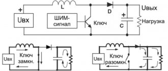
The easiest way to make 380 Volts is to purchase and install a three-phase voltage converter (inverter). A single-phase voltage of 220V is supplied to the input of this device, and three phases of 380V appear at the output terminals of the device. This is the best, although the most expensive, method of obtaining three-phase power.
Structurally, the inverter consists of four units - a rectifier and three converters that convert 220 V DC into AC. Due to the appropriate settings and connections of the nodes, the individual phases are shifted by 120°, which ultimately gives a linear voltage of 380 V.
Most inverters have a built-in voltage stabilizer and various types of protection that turn off the power in case of overload, short circuit or high input voltage.
Winding connection methods
Engines in everyday life and in amateur practice drive a variety of mechanisms - a circular saw, an electric plane, a fan, a drilling machine, and pumping equipment. Without knowing how electric motors work, it is better not to get into the weeds with frequency drives. Engines are:
Depending on the number of poles, the units are one-, two-, or three-pole. In the stator core of the latter there is a winding for each phase, the ends of which are brought out to the terminal box. How can you increase the speed of an asynchronous motor (IM) without losing power? By changing the number of pole pairs.
To move on to other methods, and there are two more of them, we cannot do without the symbols “star” and “triangle”. The three windings of the coil can be connected in two ways: at a point or in a circle, hence the names of the connections “star” and “triangle”.
How to make 380 volts from 220: 5 ways
This shift is provided by the arrangement of the windings in the generators in the power plant and is necessary to provide torque to the electric motors. In addition, the phase shift allows you to reduce the cross-section of the neutral wire.
Expert opinion
It-Technology, Electrical power and electronics specialist
Ask questions to the “Specialist for modernization of energy generation systems”
Frequency converter 220 V output 3 phase Single-phase voltage is a special case of three-phase voltage and is obtained by connecting the consumer to the phase and neutral wires. Ask, I'm in touch!
How to connect a three-phase motor to a 220 V network
The use of a three-pole AD in a single-phase electrical network is of interest to many owners of private houses. The units are increasingly in demand in households. They are quite simple in design and easy to use. However, in terms of connecting the motor to a single-phase network, not everything is so simple.
The pulsating field of a single-phase current is not capable of causing the rotor of an electric motor to rotate - such a current must be converted into multiphase and then only supplied to the unit.
Where frequency converters are used single-phase input-output 1 ph. 220 V
Asynchronous motors (AM) are more often used in everyday life than in industry, in particular in the system of single-pole duct fans and water pumps. It is no secret that difficulties arise associated with adjusting the rotation speed of blood pressure. This is the task of single-pole input-output frequency converters 220-220.
Uneven torque may cause abnormal noise and vibration in the unit. To regulate the speed of three-phase electric motors, single-pole 220/380 V frequency changers (input/output) are used, sometimes with a special controller used to control the device.
These types of converters are intended for use in technological (pumps and fans, transport mechanisms, extruders, mixers, etc.) and energy-saving equipment (pump control stations, climate and air conditioning systems, etc.). Models are available with the possibility of mounting on a DIN rail. They have a wide range of output frequency adjustment. The smart control panel provides a comfortable working environment.
In order to avoid complications that are often encountered during the operation of 3-pole electric motors in single-phase networks, you should adhere to the following rules:
- the power of the engine used as a state of emergency is selected greater than the power of the electric drive connected to it;
- in practice, 4 kW converters are capable of solving all existing economic problems in a private home. You can focus on a load of 2-3 kW, which is acceptable for the power grid;
- the operating current of the converter in normal mode must be greater than its value indicated in the passport of this type of electric motor (otherwise the power supply will simply burn out);
- The converter is connected in a strict sequence: the emergency starts first, then the 3-pole consumers. The equipment is turned off in the reverse order.
Using a special inverter
There are many different models of single-phase to three-phase voltage converters on the market. Their price for the same power depends on:
- quality of the output voltage sinusoid;
- the presence of various protections (for example, against load loss in one of the phases, overload of input voltage, output current, over temperature);
- the possibility of smooth acceleration of an asynchronous engine;
- control the speed and direction of rotation of the electric motor shaft;
- remote control capabilities;
- sensor, filters, auxiliary units and accessories.
Which of the listed methods is optimal for the reader is determined by their comparison in specific conditions. The information provided is quite sufficient for this.
Expert opinion
It-Technology, Electrical power and electronics specialist
Ask questions to the “Specialist for modernization of energy generation systems”
How to make 380 volts from 220 - converter options The pulsating field of a single-phase current is not capable of causing the rotor of an electric motor to rotate; such current must be converted into multiphase and then only supplied to the unit. Ask, I'm in touch!
Frequency converter 220-380, whose company is better?
Let's answer the question to the point. There are countless Asian manufacturers on the sales market of such equipment. Let's stop listing. The domestic emergency assembler is a kind of lottery (sometimes it depends on what day of the week the device is assembled).
Frequency drivers from Siemens usually fully meet the requirements. Products produced by ABB or Danfoss are quite easy to set up. It is better than others in terms of price and quality. Buy without hesitation. Judging by the reviews, they have a very decent device. Dynamic performance is enhanced by vector control, which also provides high torque at low frequencies during starting and running.
Universal compact CP models do an excellent job of converting network parameters; their obvious advantages are expressed in the following:
- the ability to generate “full” three-phase current;
- no loss in engine power;
- Suitable for any electric motor design;
- The constructivity is very simple.
- own energy consumption is minimal.