Stages of installation of power line towers
Even at the stage of preparatory work, the power line route is being laid: cleaning the route, leveling the ground and other work.
The route markings are carried out strictly in accordance with the project. When marking, the installation locations of the supports are noted, as well as their delivery to the installation sites. Depending on the design of the supports, they can be supplied disassembled or assembled. The disassembled supports are assembled near the installation site. The required traverses and other linear equipment are hung on the assembled support.
Before assembling the supports or in parallel with the assembly, pits or pits are dug to install the supports. The design of the pits and the dimensions of the pits are also specified in the project. For main power lines and overhead power lines, pits and pits are not dug manually. Drilling rigs are used for this.
Metal supports are placed on pre-made concrete foundations. Wooden supports and reinforced concrete supports for 0.4-6 kV power lines are installed without a foundation. To strengthen the stability of the support, a transverse console is placed at the end of the support in the ground (though not always). For 6-10 kV power lines, they are installed without a foundation, but with the surface of the support being poured with concrete. Power transmission line supports of 35-500 kV are installed with a cover at the end of the support dug into the ground (to strengthen the support) and pouring the support in the ground and the base of the support with concrete. Exceptions may be support trusses in the shape of the letter “P”.
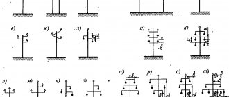
a-Intermediate support; b- anchor support with a strut, placed at angles of rotation of power lines from 20 to 90 degrees. 10 Support, 5-strut (sub support)
The usual design of pits for wooden and concrete power transmission line supports up to 1 kV are cylindrical in shape, 1100-1500 mm deep and 100 mm wider in diameter than the size of the support. Such pits are made using drilling rigs.
Note: In cramped conditions, as well as with small volumes, a hole for support can be dug manually. The profile of the pit should not be cylindrical, but stepped.
Rolling out
Before you begin rolling, temporary rolling rollers should be placed on the supports, which may differ in design and have one (A), two (B) or four (C) support rollers.
As for technological solutions to the problem, there are two of them:
- Using fixed rolling equipment such as jacks, trestles and special machines. This technique is justified when laying short lines, in the area of which the risk of damage to wires is minimal.
- Using mobile means of mechanization of cable conveyors, sleds, carts, etc. This technology has proven itself well when laying long-distance overhead lines. It minimizes the risk of cable damage.
Technology for installing supports using cranes
The technology for installing supports using the first three mechanisms is basically the same. The assembled support is laid along the axis of the overhead line. The center of gravity of the support is 1500 mm from the middle of the pit. The sling is attached to the support above its center of gravity. The second end of the sling is attached to the crane hook. The support rises. To hold it, retaining slings are attached to it along the length of the support. They are held by hands, if the support is small, or by transverse winches.
The raised support, sufficiently 20-30 cm from the ground, is directed into the pit and installed, securing the vertical position with temporary supports or guy wires.
Heavy rack supports (up to 25 meters weighing up to 7000 kg) are installed with a special installation machine, K-LEP-7.
Tension and fastening
Before installing the wires on intermediate supports, they must be tensioned so that they do not touch the ground or other objects and do not sag beyond the permissible limits. For this, it is possible to use various devices, starting with manual pliers and paws, and ending with complex automatic mechanization systems. Stretched electrical wiring:
- Attached to anchors.
- Connect with garlands of insulators.
- Fasten to pre-prepared fastening points.
Installation of supports by crane and tractor
Installation of supports using a crane and tractor has two options:
- Installation by stationary crane and tractor;
- Installation by tractor and crane on a wheeled base.
Installation by stationary crane and tractor
- The support is placed along the axis of the overhead line. Traction cables are attached to the bottom and top of the support;
- The lower cable is attached to the tractor winch. The crane stands at the pit and lifts the support above the ground. In this case, the tractor winch holds the bottom of the support. In this “suspended form” the support is lowered into the pit;
- The lower cable is detached from the tractor winch. Now the upper cable is attached to the winch, which begins to tighten;
- When the crane cable weakens, it is unfastened, and the support is held in place by the tractor and two side winches with temporary braces.
Installation by tractor and crane on wheel base
With this setup, things happen a little differently. The tractor is placed across the road, a meter from the pit. The support is laid along the route at a distance of 1500-2000 mm from the edge of the pit. The support is crushed by the crane and held in place by the tractor. Raising the support, its edge is installed in the pit. The tractor increases the tension of the support, while weakening the crane cable. When the entire load is transferred to the tractor, the crane is disconnected and moved to a safe distance. The final lifting of the support is done by a tractor.
Installation of electrical installations - Installation of overhead line insulators
Page 75 of 83
When installing insulators, the following requirements are observed [2]: on the route, before installation, the insulators must be inspected and rejected. The resistance of porcelain insulators for overhead lines with voltages above 1 kV must be checked before installation with a 2500 V megohmmeter, and the insulation resistance of each suspended insulator or each element of a multi-element pin insulator must be at least 300 MOhm. Cleaning insulators with steel tools is not allowed. Electrical testing of glass insulators is not carried out. On overhead lines with pin insulators, the installation of traverses, brackets and insulators should, as a rule, be carried out before lifting the support. Hooks and pins must be firmly installed in the rack or support beam; their pin part must be strictly vertical. To protect against rust, hooks and pins should be coated with asphalt varnish. Pin insulators should be firmly screwed strictly vertically onto hooks or pins using polyethylene caps (Fig. 13 21). The caps must be selected to match the type of insulator and the size of the hook or pin. Before attaching the caps, a notch is made at the ends of the hooks (pins) along the depth of the cap. Before fitting, the caps are immersed for 5-7 minutes in water heated to 80-90 °C. Fig. 13 22 An example of determining the creepage path length of a pin porcelain insulator ShF 10 A-B - creepage path length. 1 - polyethylene cap, 2 - steel pin, 3 - traverse, 4 - wire Fig. 13.21 Polyethylene cap for fastening pin insulators. The heated cap is placed on the hook (pin) with light blows of a wooden hammer to the full depth of the cap. The pin insulator is screwed onto the hook (pin). ) cap by hand until it stops. In this case, in order to avoid distortion, it is necessary to direct the insulator strictly along the thread; distortions are not allowed. Installation of pin insulators with an inclination of up to 45° to the vertical is allowed when attaching descents to devices and support loops. On overhead lines with suspended insulators, parts of the coupling fittings of the insulating pendants must be cottered, and locks must be placed in the sockets of each element of the insulating pendant. All locks in insulators must be located on the same straight line. Locks in insulators of supporting insulating suspensions should be placed with their input ends towards the support post, and in tension insulators and fittings of insulating suspensions - with their input ends downwards. Vertical and inclined pins should be positioned with the head up and the nut or cotter pin down. According to [3], the number of suspended insulators with a creepage distance of at least 25 cm (Fig. 13.22) in garlands of 6-35 kV overhead lines is recommended to be taken as follows: for overhead lines up to 10 kV - one, 20 kV - two, 35 kV - three. On a 35 kV overhead line with wooden supports, it is recommended to use two insulators in a supporting garland. Pin insulators mounted on hooks are installed directly on the trunks of wooden supports without traverses. Holes are drilled in the support using a drill (see above requirements [2]), into which the tails of the hooks are screwed. To make it easier to tighten the hooks, a special key is used. Insulators mounted on pins are installed on cross-beams. In this case, the pin is secured to the traverse using a nut. Garlands of pendant insulators are suspended on the traverses of the supports on hooks and earrings. Their installation on a support is usually carried out from a telescopic tower. The garlands are lifted using a cable (or rope) thrown over a block mounted on a traverse. To speed up the suspension and secure the garlands to the support, use special mounting brackets (SKM) or mounting links (MPL) (Fig. 13.23, a). In this case, a mounting bracket or mounting link is connected to the earring of the upper insulator of the garland before lifting it onto the support. The end of the lifting cable is moored to a regular bracket (see Fig. 13.15, a), to which a mounting bracket or mounting link is connected. The garland is raised to a position in which the eye of the free arm of the mounting link coincides with the eye of a conventional bracket attached to the support. After this, this end of the mounting link is attached and pinned to a regular bracket on the support. Then the lifting cable is loosened, at the same time the mounting link is rotated 90 degrees and the garland is suspended in its working position on the support.
Rice. 13 23 Suspension of garlands using a mounting link a - general view of the PRM link, b - schematic diagrams of lifting and fastening garlands, 1 - position of the garland during lifting, 2 - working position of the garland, 3 - moving the mounting link to the working position after engaging the garland to the support Then the second end of the mounting link is uncoiled and disconnected from a conventional bracket fastened to a lifting cable. Before lifting, strings of insulators are assembled on the ground, usually on special trestles. Heavy garlands are collected in a vertical position. To do this, the first element is suspended on a special stand or attached to a rope, with the help of which the garland is lifted onto the support. All elements of the coupling fittings are pinned, and locks are installed in the sockets of each element, observing the requirements [2] given above.
- Back
- Forward
Lifting the support manually
Of course, the only option left is to lift the supports manually. You can manually lift a wooden support for a 0.4 kV overhead line. The edge of the support is placed on the edge of the pit (pit), the cable is attached above the center of gravity of the support. When lifting the support, the support walkways are constantly rearranged from the top to the bottom of the support. The installed support is leveled, backfilled and compacted.
©Elesant.ru
Other articles in the section: Power lines
- Types of power transmission line supports by material
- Types of supports by purpose
- Overhead power lines with SIP wires
- Wooden supports for overhead power lines
- Reinforced concrete power transmission line supports
- Reinforced concrete power transmission line supports
- Power line support structures
- Tension of overhead power line wires
- SIP installation mistakes that should not be made
- Preparatory work for installation of overhead power lines