What is portable grounding and its purpose
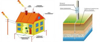
Portable grounding (PG) is a special product designed for grounding individual sections of an electrical installation that do not have stationary grounding blades. The main function of the PP is to ensure the safety of workers when carrying out repair work.
This is what portable grounding looks like
Installing a PZ allows you to protect personnel from exposure to electric current due to erroneous, spontaneous supply of voltage, as well as as a result of the formation of induced voltage. When voltage is applied to a grounded section of the electrical network, a short circuit current is generated, which leads to the launch of protection, followed by disconnection of the voltage source.
Device
There are two main options for using PP. The first option is intended for use in switchgears, and the second - on overhead power lines. Grounding can be made in single-phase or three-phase design.
The PZ can be made in three design variations: rod, rod with a metal link (ZPL-10) and rodless (ZPP-15).
Portable grounding type ZLP-10
The design of the product consists of the following elements:
- flexible conductor (copper or aluminum);
- fastening clips;
- tips (clamps);
- dielectric rod.
The rodless design of the PZ is usually used for use in complete switchgears.
Example of a rodless PZ design
To simultaneously short-circuit three phases through a single grounding conductor, a three-phase grounding conductor is used.
Single-phase version of portable grounding is intended for separate connection of phases to the grounding loop. Used on power lines with a voltage level of more than 110 kV. This is due to the significant distance from the grounding bus to the phase wires and the phase-to-phase span.
The flexible conductor may be coated with transparent insulation. It can be made of aluminum or copper wires. Using clamps, the PZ is attached to live parts and to the ground loop. The device of phase clamps can be made in the form of clamps and copper tips. The clamps are tightened using an insulating rod, with the help of which the minimum permissible distance to live parts is achieved.
Rules for labor protection during the operation of electrical installations (page 4)
XVI. Labor protection when performing technical activities,
ensuring the safety of work with stress relief
16.1. When preparing a workplace with voltage relief, in which the voltage is removed from the current-carrying parts of the electrical installation on which work will be carried out by disconnecting switching devices, disconnecting busbars, cables, wires and measures are taken to prevent the supply of voltage to the current-carrying parts to the place of work, there must be The following technical measures were carried out in the specified order:
the necessary shutdowns have been made and measures have been taken to prevent the supply of voltage to the work site due to erroneous or spontaneous switching on of switching devices;
prohibiting posters must be posted on manual drives and on remote control keys of switching devices;
checked that there is no voltage on live parts that must be grounded to protect people from electric shock;
grounding installed;
“Grounded” signposts have been posted, workplaces and live parts that remain energized have been fenced off if necessary, and warning and instructional posters have been posted.
XVII. Occupational safety during shutdowns in electrical installations
17.1. When preparing the workplace, the following should be disabled:
live parts on which work will be carried out;
unfenced live parts, to which people, machinery and lifting machines may accidentally approach at a distance less than that specified in Table No. 1;
control and power supply circuits for the drives, the air in the control systems of the switching devices is closed, the springs and weights at the drives of the switches and disconnectors are removed.
17.2. In electrical installations with voltages above 1000 V, there must be a visible gap on each side from which switching on the switching device does not exclude the supply of voltage to the workplace. A visible break may be created by disconnecting disconnectors, removing fuses, disconnecting separators and load switches, disconnecting or removing busbars and wires.
In the absence of a visible break, in complete factory-made switchgear with withdrawable elements, as well as in complete switchgear with gas insulation (hereinafter referred to as GIS) with a voltage of 35 kV and above, it is allowed to check the disconnected position of the switching device using a mechanical indicator of the guaranteed position of the contacts.
Power transformers and voltage transformers associated with the section of the electrical installation allocated for work must be disconnected and their circuits must also be disassembled from their other windings to eliminate the possibility of reverse transformation.
When remotely controlling switching devices from a workplace, allowing operational personnel performing operational maintenance of electrical installations to remotely (from a computer monitor) control switching devices, grounding blades of disconnectors and determine their position, use electrical connection diagrams of electrical installations displayed on a computer monitor, electrical parameters ( voltage, current, power), as well as to read incoming emergency and warning signals (hereinafter referred to as the automated workstation of operational personnel (AWP)), personnel are not allowed to be in the switchgears in which these switching devices are located.
17.3. After disconnecting switches, disconnectors (isolators) and manually operated load switches, you must visually verify that they are disconnected and that there are no bypass jumpers.
When remotely controlling switching devices with an automated workplace, the position of switching devices (switches, disconnectors, grounding knives) is checked using the automated workplace alarm. General monitoring of the condition of switching devices is carried out by means of technological video surveillance. A visual check of the actual position of the switching devices must be performed after completing the entire complex of operations directly at the installation site of the switching devices.
17.4. In electrical installations with voltages above 1000 V, to prevent erroneous or spontaneous switching on of switching devices that supply voltage to the place of work, the following measures must be taken:
For disconnectors, separators, load switches, manual drives in the off position must be locked with a key or a removable handle (hereinafter referred to as a mechanical lock). In kV electrical installations with single-pole disconnectors, instead of a mechanical lock, it is allowed to put dielectric caps on the knives;
for disconnectors controlled by an operating rod, stationary fences must be locked with a mechanical lock;
For drives of switching devices that have remote control, the power circuits and control circuits must be turned off, and for pneumatic drives, in addition, on the compressed air supply pipeline, the valve must be closed and locked with a mechanical lock and compressed air must be released, while the drain valves must be left in the open position;
when remotely controlled from an automated workstation, the power circuits of the disconnector drives must be turned off, the operating mode selection key in the control cabinet is set to the “local control” position, the disconnector control cabinet is locked with a mechanical lock;
for load and spring drives, the closing weight or closing springs must be brought to the non-working position;
Prohibition posters must be posted.
Measures to prevent erroneous switching on of switchgear switching devices with withdrawable trolleys must be taken in accordance with the requirements provided for in paragraphs 29.1, 29.2 of the Rules.
17.5. In electrical installations with voltages up to 1000 V, the voltage must be removed from all live parts on which work will be carried out by disconnecting manually operated switching devices, and if there are fuses in the circuit, by removing them. If there are no fuses in the circuit, preventing the switching devices from being switched on incorrectly must be ensured by such measures as locking the handles or doors of the control cabinet, closing the buttons, and installing insulating pads between the contacts of the switching device. When removing voltage using a remote-controlled switching device, it is necessary to open the secondary circuit of the switching coil.
The listed measures can be replaced by disconnecting or disconnecting the cable or wires from the switching device or from the equipment on which work is to be carried out.
Prohibition posters must be posted.
17.6. The disconnected position of switching devices with voltages up to 1000 V with contacts inaccessible for inspection is determined by checking the absence of voltage at their terminals or at the outgoing busbars, wires or terminals of the equipment included by these switching devices. Checking the absence of voltage in complete factory-made switchgear can be done using built-in stationary voltage indicators.
XVIII. Hanging prohibition posters
18.1. On the drives (drive handles) of manually controlled switching devices (switches, separators, disconnectors, knife switches, automatic machines), in order to avoid the supply of voltage to the workplace, posters “Do not turn on! People are working."
For single-pole disconnectors, posters are hung on the drive of each pole, for disconnectors controlled by an operating rod on the fences. On the valves that block air access to the pneumatic drives of the disconnectors, a poster “Do not open! People are working."
At connections with voltages up to 1000 V that do not have switching devices, the poster “Do not turn on! People are working” must be posted near the removed fuses, in switchgear - in accordance with clause 29.2 of the Rules.
Posters must be posted on keys and buttons of remote and local control, as well as on automatic machines or at the location of removed fuses of control circuits and power supply circuits of switching device drives.
When remotely controlling switching devices with an automated workplace, similar safety posters must, in addition, be displayed next to the graphic designation of the corresponding switching device on the automated workplace diagram.
18.2. On the drives of switching devices that are switched off for work on overhead lines or cable lines, regardless of the number of working crews, one poster “Do not turn on! Work on the line." When remotely controlling switching devices with automated workstations, the prohibitory sign “Do not turn on! Work on the line! is displayed on the diagram next to the symbol of the switching device that supplies voltage to the overhead line or cable line. This poster is hung and removed at the direction of the operational personnel who keep track of the number of crews working on the line.
XIX. Occupational safety when checking the absence of voltage
19.1. It is necessary to check the absence of voltage with a voltage indicator, the serviceability of which must be established before use using special devices intended for this purpose or by approaching live parts that are known to be energized.
In electrical installations with voltages above 1000 V, it is necessary to use dielectric gloves when using the voltage indicator.
In factory-made complete switchgears (including those filled with SF6 gas), the absence of voltage is checked using built-in stationary voltage indicators.
In electrical installations with a voltage of 35 kV and above, to check the absence of voltage, you can use an insulating rod by touching it several times to live parts. A sign of lack of tension is the absence of sparking and crackling. On single-circuit overhead lines with a voltage of 330 kV and above, a sufficient sign of the absence of voltage is the absence of corona.
When remotely controlling switching devices and grounding knives with an automated workplace, it is allowed to check the absence of voltage, which is carried out before turning on the grounding knives by checking the diagram displayed on the automated workplace monitor. For SF6 equipment - with appropriate operational interlock and permission from the manufacturer.
19.2. In the switchgear, one employee from among the operating personnel who has group IV in electrical installations with voltages above 1000 V, and who has group III in electrical installations with voltages up to 1000 V is allowed to check the absence of voltage.
On overhead lines, the absence of voltage must be checked by two workers: on overhead lines with voltages above 1000 V - workers with groups IV and III, on overhead lines with voltages up to 1000 V - workers with group III.
19.3. It is allowed to check the absence of voltage by checking the circuit in situ:
in outdoor switchgear, switchgear and complete transformer substation (hereinafter referred to as KTS) of outdoor installation, as well as on overhead lines during fog, rain, snowfall in the absence of special voltage indicators;
in outdoor switchgear with a voltage of 330 kV and higher and on double-circuit overhead lines with a voltage of 330 kV and higher.
When calibrating the circuit in situ, the absence of voltage at the inputs of overhead lines and cable lines is confirmed by the person on duty, in whose operational control the lines are located.
Verification of overhead lines in kind consists of checking the direction and external signs of the lines, as well as the designations on the supports, which must correspond to the dispatcher names of the lines.
19.4. On overhead lines, when hanging wires at different levels, check the absence of voltage with a pointer or rod and install grounding from bottom to top, starting from the bottom wire. With a horizontal suspension, the check should begin with the nearest wire.
19.5. In electrical installations with voltages up to 1000 V with a grounded neutral, when using a two-pole indicator, it is necessary to check the absence of voltage both between the phases and between each phase and the grounded equipment body or protective conductor. It is allowed to use a previously tested voltmeter. The use of control lamps is prohibited.
19.6. Devices signaling the device's off position, blocking devices, and constantly switched on voltmeters are only additional means of confirming the absence of voltage, and based on their readings one cannot make a conclusion about the absence of voltage.
XX. Occupational safety when installing grounding
20.1. It is necessary to install grounding connections to live parts immediately after checking the absence of voltage.
20.2. Portable grounding must first be connected to a grounding device, and then, after checking that there is no voltage, installed on live parts.
It is necessary to remove portable grounding in the reverse order: first remove it from live parts, and then disconnect it from the grounding device.
20.3. Installation and removal of portable grounding connections must be carried out wearing dielectric gloves and using an insulating rod in electrical installations with voltages above 1000 V. The portable grounding clamps should be secured with the same rod.
When installing, removing portable grounding or performing work, it is prohibited to touch the conductive parts of the grounding.
20.4. It is prohibited to use conductors for grounding that are not intended for this purpose, except for the cases specified in paragraph 27.2 of the Rules.
XXI. Occupational safety when installing grounding in switchgears
21.1. In electrical installations with voltages above 1000 V, the current-carrying parts of all phases (poles) of the area disconnected for work must be grounded on all sides from where voltage is supplied, with the exception of switchgear busbars disconnected for operation, on which it is sufficient to install one grounding.
When working on a disconnected line disconnector, additional grounding must be installed on the descent wires from the overhead line side, regardless of the presence of grounding blades on the disconnector, which is not disturbed when manipulating the disconnector.
21.2. Grounded live parts must be separated from live parts under voltage by a visible break. The absence of a visible gap is allowed in the cases specified in paragraph 17.2 of the Rules.
Installed ground connections can be separated from live parts on which work is directly carried out by disconnected switches, disconnectors, separators or load switches, removed fuses, dismantled buses or wires, and withdrawable elements of complete devices.
Directly at the workplace, grounding to live parts must additionally be installed in cases where these parts may be under induced voltage (potential).
21.3. Portable grounding connections should be connected to live parts in areas cleared of paint.
21.4. In electrical installations with voltages up to 1000 V, when working on the busbars of switchgear switchgears, switchboards, assemblies, the voltage from the busbars must be removed and the busbars (with the exception of busbars made with insulated wire) must be grounded. The need and possibility of grounding connections of these switchgears, switchboards, assemblies and equipment connected to them is determined by the issuing order or order.
21.5. Temporary removal of ground connections installed during preparation of the workplace is permitted if this is required by the nature of the work performed (measurement of insulation resistance).
Temporary removal and reinstallation of groundings is carried out by operational personnel or at the direction of the employee issuing the work order, the work foreman.
Permission for the temporary removal of groundings, as well as for the performance of these operations by the work contractor, must be included in the “Separate instructions” line of the work order with a record of where and for what purpose the groundings should be removed.
21.6. In electrical installations, the design of which is such that the installation of grounding is dangerous or impossible (for example, in some distribution boxes, switchgear of certain types, assemblies with a vertical phase arrangement), additional measures must be developed to ensure work safety, including the installation of dielectric caps on the disconnector blades, switches of dielectric pads or disconnection of wires, cables and tires. The list of such electrical installations is approved by the employer and brought to the attention of employees.
21.7. In electrical installations with voltages up to 1000 V, installation and removal of grounding operations are allowed to be performed by one employee with group III, from among the operating personnel.
21.8. In electrical installations with voltages above 1000 V, two workers must install portable grounding connections: one with group IV (from among the operating personnel), the other with group III; an employee with group III has the right to be among the repair personnel, and when performing work on grounding consumer connections - from the consumer personnel. At remote substations, with the permission of administrative, technical or operational personnel, when installing grounding in the main circuit, the work of a second employee with group III from among the consumer personnel is permitted; One employee with group IV from among the operational personnel has the right to turn on the grounding knives.
An employee from among the operational personnel who has group III has the right to disconnect the grounding knives and remove portable grounding connections.
XXII. Occupational safety when installing grounding on overhead lines
22.1. Overhead lines with voltages above 1000 V must be grounded in all switchgears and at sectional switching devices where the line is disconnected. Allowed:
Overhead lines with a voltage of 35 kV and above with branches should not be grounded at substations connected to these branches, provided that the overhead line is grounded on both sides, and at these grounding substations they are installed behind disconnected line disconnectors;
Overhead lines with voltage kV should be grounded only in one switchgear or at one sectioning device or on the support closest to the switchgear or sectioning device. In other switchgears of this voltage and for sectioning devices where the overhead line is disconnected, it is allowed not to ground it, provided that grounding is installed on the overhead line between the workplace and this switchgear or sectioning devices. On overhead lines, the specified grounding connections should be installed on supports that have grounding devices.
On overhead lines with voltages up to 1000 V, it is sufficient to install grounding only at the workplace.
22.2. In addition to the grounding specified in clause 22.1 of the Rules, at the workplace of each team, the wires of all phases must be grounded, and, if necessary, lightning protection cables.
22.3. When installing wires in an anchor span, as well as after connecting the loops on the anchor supports of the mounted section of the overhead line, the wires (cables) must be grounded at the initial anchor support and at one of the final intermediate supports (in front of the final anchor support).
22.4. It is not allowed to ground the wires (cables) on the final anchor support of the mounted anchor span, as well as the mounted section of the overhead line, in order to avoid the transfer of potential from lightning discharges and other overvoltages from the wires (cables) of the finished section of the overhead line to the next, mounted section.
22.5. On overhead lines with split wires, only one wire is allowed to be grounded in each phase; If there are insulating struts, all phase wires must be grounded.
22.6. On single-circuit overhead lines, grounding at workplaces must be installed on the support on which work is being carried out, or on an adjacent one. It is allowed to install grounding connections on both sides of the overhead line section where the team is working, provided that the distance between the grounding connections does not exceed 2 km.
22.7. When working on a lightning protection cable isolated from a support or on a support structure, when it is necessary to approach this cable at a distance of less than 1 m, the cable must be grounded. Grounding must be installed towards the span in which the cable is isolated, or in the span at the work site.
The grounding cable should be disconnected and connected to a lightning protection cable isolated from the ground after preliminary grounding of the cable.
If ice melting is provided on this cable, before starting work the cable must be disconnected and grounded from those sides from which voltage cannot be supplied to it.
22.8. Portable grounding connections should be connected to metal supports - to their elements, to reinforced concrete and wooden supports with grounding slopes - to these slopes after checking their integrity. On reinforced concrete supports that do not have grounding slopes, it is allowed to connect grounding connections to crossbars and other metal elements of the support that have contact with the grounding device.
In electrical networks with voltages up to 1000 V with a grounded neutral, if the neutral wire is re-grounded, it is allowed to connect portable grounding connections to this neutral wire.
Places where portable ground connections are connected to grounding conductors or structures must be cleared of paint.
Portable grounding in the workplace is allowed to be connected to a grounding electrode immersed vertically in the ground for at least 0.5 m. Installation of grounding electrodes in random piles of soil is prohibited.
22.9. On overhead lines with voltages up to 1000 V, when work is carried out from supports or from a telescopic tower without an insulating link, grounding must be installed both on the wires of the line being repaired and on all wires suspended on these supports, including uninsulated wires of radio broadcasting and telemechanics lines .
22.10. On overhead lines disconnected for repairs, workers from among the operating personnel must install and then remove portable grounding connections and turn on the grounding blades available on the supports: one with group IV (on overhead lines with voltages above 1000 V) or group III (on overhead lines with voltages up to 1000 V) B), the second - having group III. It is allowed to use a second employee with group III from among the repair personnel, and on overhead lines feeding the consumer, from among the consumer’s personnel.
One employee with group III from among the operating personnel is allowed to disconnect the grounding knives.
At workplaces on overhead lines, the work manager with a team member having group III has the right to install portable grounding connections. Removal of these portable groundings is permitted at the direction of the work manager by two team members with group III.
22.11. On overhead lines, when checking the absence of voltage, installing and removing groundings, one of the two workers must be on the ground and monitor the other.
22.12. Requirements for the installation of grounding on overhead lines when working in a span of intersection with other overhead lines, on one disconnected circuit of a multi-circuit overhead line, on overhead lines under induced voltage and during phase-by-phase repairs are provided for in Chapter XXXVIII of the Rules.
XXIII. Fencing the workplace, hanging safety posters
23.1. In electrical installations, “Grounded” posters must be posted on the drives of disconnectors, separators and load switches, the erroneous activation of which does not exclude the supply of voltage to the grounded section of the electrical installation, and on the keys and remote control buttons of switching devices. When remote control is carried out from an automated workstation, the sign of the poster “Grounded” is displayed on the diagram next to the symbols of the switching devices.
23.2. For temporary fencing of live parts that remain energized, shields, screens, and screens made of insulating materials should be used.
When installing temporary fences without relieving the voltage, the distance from them to live parts must be no less than that indicated in Table 1.
In electrical installations with kV voltage, this distance can be reduced to 0.35 m.
Temporary fences must be marked with the words “Stop! Voltage!" or the corresponding posters have been strengthened.
Workplaces are fenced off with shields, screens, barriers or cords made of plant or synthetic fibers (leaving a passage) and by hanging posters “Stop! Voltage” facing inside the enclosed space.
23.3. In electrical installations with voltages up to 20 kV, in cases where it is impossible to protect live parts with shields, the use of insulating pads placed between disconnected and live parts (for example, between the contacts of a disconnected disconnector) is permitted. These pads may touch live parts that are live.
Two workers with groups IV and III using dielectric gloves and insulating rods or pliers must install and remove insulating linings on live parts of electrical installations with voltages above 1000 V.
Installation and removal of overlays in electrical installations up to 1000 V can be carried out by one worker with a group of at least III using dielectric gloves.
23.4. On the fences of cells, cabinets and panels bordering the workplace, posters “Stop! Voltage".
23.5. In outdoor switchgear, when work is carried out from the ground, and on equipment installed on foundations and individual structures, the workplace must be fenced off (leaving a passage, passage) with a rope, cord or cord made of plant or synthetic fibers with posters hanging on them “Stop! Voltage” facing inside the enclosed space.
It is allowed to use structures not included in the workplace area to suspend the rope, provided that they remain outside the enclosed space.
When removing voltage from the entire outdoor switchgear, with the exception of line disconnectors, the latter must be fenced with a rope with posters “Stop! Voltage” facing the outside of the enclosed space.
In outdoor switchgear, when working on orders in secondary circuits, there is no need to fence off the workplace.
23.6. In outdoor switchgear, in sections of structures through which one can walk from the workplace to the adjacent energized areas, clearly visible posters “Stop! Voltage". These posters have the right to be installed by an employee with group III, from among the repair personnel under the guidance of the permitting person.
On structures bordering the one on which you are allowed to climb, a poster “Do not climb! He will kill."
On stationary stairs and structures that are allowed to be climbed for work, a “Climb Here!” poster must be posted.
23.7. At prepared workplaces in electrical installations (on the equipment on which work is to be performed, as well as at the point of passage into the enclosed workplace), a “Work here” poster must be posted.
23.8. It is not allowed to remove or rearrange the posters and fences installed during the preparation of workplaces for those permitted until the work is completed, except for the cases specified in the “Separate instructions” column of the work order.
XXIV. Occupational safety when working in areas influenced by electric and magnetic fields
24.1. In outdoor switchgear and on overhead lines with a voltage of 330 kV and higher, workers must be protected from a biologically active electric field that can have a negative effect on the human body and cause the appearance of electrical discharges when touching grounded or electrically conductive objects isolated from the ground.
24.2. In electrical installations of all voltages, workers must be protected from a biologically active magnetic field that can have a negative effect on the human body.
24.3. Biologically active are electric and magnetic fields, the intensity of which exceeds the permissible value.
24.4. The maximum permissible level of intensity of the acting electric field (EF) is 25 kV/m. Staying in an ED with a voltage level exceeding 25 kV/m without the use of personal protective equipment is not permitted.
At ED voltage levels above 20 to 25 kV/m, the time spent by personnel in the ED should not exceed 10 minutes.
When the EF voltage level is over 5 to 20 kV/m, the permissible personnel stay time is calculated using the formula:
T = 50 / E - 2,
Where:
E—strength level of the influencing EF, kV/m;
T — permissible time of personnel stay, hour.
If the electric voltage level does not exceed 5 kV/m, personnel are allowed to stay in the electric zone throughout the entire working day (8 hours).
The permissible time of stay in the electric field has the right to be realized one-time or in parts during the working day. During the rest of the working time, it is necessary to use means of protection against electromagnetic fields or to be in an electrical environment with a voltage of up to 5 kV/m.
24.5. The permissible intensity (H) or induction (B) of the magnetic field for conditions of general (entire body) and local (extremities) exposure, depending on the duration of stay in the magnetic field, is determined in accordance with Table No. 3.
Table No. 3
Permissible magnetic field levels
| Stay time (hour) | Permissible magnetic field levels H (A/m)/B (µT) when exposed to | |
| in general | local | |
| <= 1 | 1600/2000 | 6400/8000 |
| 2 | 800/1000 | 3200/4000 |
| 4 | 400/500 | 1600/2000 |
| 8 | 80/100 | 800/1000 |
Allowable magnetic field levels within time intervals are determined by interpolation.
| Due to the large volume, this material is placed on several pages: 4 |
Requirements
There are many requirements for portable grounding systems. Among the main ones, thermal and dynamic stability with respect to short circuit currents stands out. The design of products should ensure ease of use.
The shorting conductors must withstand environmental influences ranging from -45 to +45 degrees. The cross-sections of the grounding conductors must correspond to the voltage levels. In electrical installations up to 1 kV, 16 square millimeters are used, and at voltages above 1 kV - 25. At a voltage level of more than six kilovolts, the cross-section of the conductors can reach one hundred and twenty square millimeters.
If there are different voltage levels in electrical installations, it is permitted to use portable grounding with the largest required cross-section to service all electrical equipment.
The product package must include technical documentation. The clamp can be fastened to the conductor cores by bolting, welding, pressing or using pressure plates. The clamp must ensure reliable contact at the application site. Insulating structures must be made of dielectric materials.
It is prohibited to use protective shells on conductive elements of the ground electrode, which interfere with visual inspection of their integrity. To insulate wires, it is allowed to use only a transparent sheath.
INSTALLATION OF GROUNDING IN DISTRIBUTION DEVICES
3.5.1.In electrical installations with voltages above 1000 V, current-carrying parts of all phases (poles) of the area disconnected for work must be grounded on all sides from where voltage can be supplied, with the exception of busbars disconnected for work, on which it is sufficient to install one grounding.
When working on a disconnected line disconnector, additional grounding must be installed on the descent wires from the overhead line side, regardless of the presence of grounding blades on the disconnector, which is not disturbed when manipulating the disconnector.
3.5.2.Grounded live parts must be separated from live parts under voltage by a visible break. There may be no visible gap in the cases specified in clause 3.1.2.
Installed ground connections can be separated from live parts on which work is directly carried out, by disconnected switches, disconnectors, separators or load switches, removed fuses, dismantled buses or wires, and withdrawable elements of complete devices.
Directly at the workplace, grounding for current-carrying parts must additionally be installed in cases where these parts may be under induced voltage (potential).
(Changed edition. Amended from 07/01/2003).
3.5.3.Portable grounding connections should be connected to live parts in areas cleared of paint.
3.5.4.In electrical installations with voltages up to 1000 V, when working on the busbars of switchgear switchgears, switchboards, assemblies, the voltage from the busbars must be removed and the busbars (with the exception of busbars made with insulated wire) must be grounded. The need and possibility of grounding connections of these switchgears, switchboards, assemblies and equipment connected to them is determined by the issuing order or order.
3.5.5. Temporary removal of grounding connections installed during preparation of the workplace is allowed if this is required by the nature of the work being performed (measuring insulation resistance, etc.).
Temporary removal and reinstallation of groundings is carried out by operational personnel or on the instructions of the work contractor issuing the work order.
Permission for the temporary removal of groundings, as well as for the performance of these operations by the work manufacturer, must be included in the work order line “Separate instructions” (Appendix No. 4 to these Rules) with a record of where and for what purpose the groundings should be removed.
3.5.6.In electrical installations, the design of which is such that the installation of grounding is dangerous or impossible (for example, in some distribution boxes, switchgear of certain types, assemblies with a vertical phase arrangement), additional measures must be developed to ensure work safety, including the installation of dielectric caps on the blades of disconnectors, dielectric pads or disconnecting wires, cables and buses. The list of such electrical installations is approved by the employer and brought to the attention of the personnel.
3.5.7.In electrical installations with voltages up to 1000 V, installation and removal of grounding operations are allowed to be performed by one employee with group III, among the operating personnel.
3.5.8.In electrical installations with voltages above 1000 V, portable grounding must be installed by two workers: one with group IV (from among the operating personnel), the other with group III; an employee with group III may be from among the repair personnel, and when grounding consumer connections, from the consumer personnel. At remote substations, with the permission of administrative, technical or operational personnel, when installing grounding in the main circuit, the work of a second employee with group III is permitted from among the consumer personnel; One employee with group IV from among the operating personnel can turn on the grounding knives.
An employee from among the operational personnel who has group III can disconnect the grounding knives and remove portable grounding connections alone.
INSTALLATION OF GROUNDING ON OHL
3.6.1. Overhead lines with voltages above 1000 V must be grounded in all switchgears and at sectional switching devices where the line is disconnected. The following is allowed:
Overhead lines with a voltage of 35 kV and above with branches should not be grounded at substations connected to these branches, provided that the overhead line is grounded on both sides, and at these grounding substations they are installed behind disconnected line disconnectors;
Overhead lines with a voltage of 6 - 20 kV must be grounded only in one switchgear or at one sectioning device, or on the support closest to the switchgear or sectioning device. In other switchgears of this voltage and for sectioning devices where the overhead line is disconnected, it is allowed not to ground it, provided that grounding is installed on the overhead line between the workplace and this switchgear or sectioning devices. On overhead lines, the specified grounding connections should be installed on supports that have grounding devices.
On overhead lines with voltages up to 1000 V, it is sufficient to install grounding only at the workplace.
3.6.2. In addition to the grounding specified in clause 3.6.1 of these Rules, at the workplace of each team, the wires of all phases must be grounded, and, if necessary, game-proof cables.
3.6.3.When installing wires in an anchor span, as well as after connecting the loops on the anchor supports of the mounted section of the overhead line, the wires (cables) must be grounded at the initial anchor support and at one of the final intermediate supports (in front of the final anchor support).
3.6.4.It is not allowed to ground the wires (cables) at the final anchor support of the reinstalled anchor span, as well as the mounted section of the overhead line, in order to avoid the transfer of potential from lightning discharges and other overvoltages of the wires (cables) of the finished section of the overhead line to the next, mounted section.
3.6.5.On overhead lines with split wires, it is allowed to ground only one wire in each phase; If there are insulating struts, all phase wires must be grounded.
3.6.6.On single-circuit overhead lines, grounding at workplaces must be installed at the support on which work is being carried out, or at an adjacent one. It is allowed to install grounding connections on both sides of the overhead line section where the team is working, provided that the distance between the grounding connections does not exceed 2 km.
3.6.7.When working on a lightning protection cable isolated from a support or on a support structure, when it is necessary to approach this cable at a distance of less than 1 m, the cable must be grounded. Grounding must be installed towards the span in which the cable is insulated, or in the span at the work site.
The grounding cable should be disconnected and connected to a lightning protection cable isolated from the ground after preliminary grounding of the cable.
If ice melting is provided on this cable, before starting work the cable must be disconnected and grounded on those sides from which voltage can be supplied to it.
3.6.8.Portable grounding connections should be connected to metal supports - to their elements, to reinforced concrete and wooden supports with grounding slopes - to these slopes after checking their integrity. On reinforced concrete supports that do not have grounding slopes, it is possible to connect grounding connections to traverses and other metal elements of the support that have contact with the grounding device.
In electrical networks with voltages up to 1000 V with a grounded neutral, if the neutral wire is re-grounded, it is allowed to connect portable grounding connections to this neutral wire.
The places where portable ground connections are connected to grounding conductors or structures must be cleared of paint.
Portable grounding at the workplace can be connected to a ground electrode immersed vertically in the ground for at least 0.5 m. Installation of ground electrodes in random piles of soil is not allowed.
3.6.9.On overhead lines with voltages up to 1000 V, when work is carried out from supports or a telescopic tower without an insulating link, grounding must be installed both on the wires of the line being repaired and on all wires suspended on these supports, including uninsulated wires of radio broadcasting and telemechanics lines.
3.6.10. On overhead lines disconnected for repairs, workers from among the operating personnel must install and then remove portable grounding connections and turn on the grounding blades available on the supports: one with group IV (on overhead lines with voltages above 1000 V) or group III (on overhead lines with voltages up to 1000 V), the second - having group III. It is allowed to use a second employee with group Ш from among the repair personnel, and on overhead lines feeding the consumer - from among the consumer’s personnel.
One employee with group III from among the operating personnel is allowed to disconnect the grounding knives.
At workplaces on overhead lines, portable grounding connections can be installed by the work supervisor and a team member with group III. These portable grounding connections can be removed, as directed by the work manager, by two team members with group III.
3.6.11.On overhead lines, when checking the absence of voltage, installing and removing groundings, one of the two workers must be on the ground and monitor the other.
3.6.12. Requirements for installing grounding connections on overhead lines when working near intersections with other overhead lines, on one disconnected circuit of a multi-circuit overhead line, on overhead lines under induced voltage and during phase-by-phase repairs are given in Section 4.15 of these Rules.
Calculation of cross-section for PZ
The minimum cross-section of the grounding conductor is determined by the formula:
Smin = (Ik.z.*√t)/C
- I short circuit – maximum current value during a short circuit;
- √t – the longest response time of the main protective devices to disconnect a short circuit;
- C is the calculated coefficient, which reflects the change in the resistance of the material under the influence of heat.
The longest time to disconnect a short circuit is taken to be the total value of the following indicators:
- activation time of the main protection;
- response time of automatic restart (reclose);
- duration of machine shutdown.
The calculated value of I short circuit depends on the type of neutral of the electrical network. With a grounded neutral, the value of single-phase short circuit current is used, with an isolated neutral - three-phase.
Chapter 2.7. Grounding devices
2.7.1. This chapter applies to all types of grounding devices, potential equalization systems, etc. (hereinafter referred to as grounding devices). 
2.7.2. Grounding devices must comply with the requirements of state standards, rules for electrical installations, building codes and regulations and other regulatory and technical documents, ensure conditions for the safety of people, operating modes and protection of electrical installations. 
2.7.3. Admission to operation of grounding devices is carried out in accordance with established requirements. 
When commissioning a grounding device, the installation organization must provide documentation in accordance with established requirements and rules. 
2.7.4. The connection of grounding conductors to the grounding conductor and grounding structures must be made by welding, and to the main grounding clamp, housings of devices, machines and overhead line supports - by bolting (to ensure the possibility of making measurements). Contact connections must meet the requirements of state standards. 
2.7.5. Installation of grounding conductors, grounding conductors, connection of grounding conductors to grounding conductors and equipment must comply with the established requirements. 
2.7.6. Each part of the electrical installation that is subject to grounding or grounding must be connected to the grounding or grounding network using a separate conductor. The serial connection of several elements of an electrical installation with grounding (neutral) conductors is not allowed. 
The cross-section of grounding and neutral protective conductors must comply with the rules for electrical installations. 
2.7.7. Openly laid grounding conductors must be protected from corrosion and painted black. 
2.7.8. To determine the technical condition of the grounding device, visual inspections of the visible part, inspections of the grounding device with selective opening of the soil, and measurement of the parameters of the grounding device must be carried out in accordance with the electrical equipment testing standards (Appendix 3). 
2.7.9. Visual inspections of the visible part of the grounding device must be carried out according to a schedule, but at least once every 6 months, by the person responsible for the electrical equipment of the Consumer or an employee authorized by him. 
During the inspection, the condition of the contact connections between the protective conductor and the equipment, the presence of anti-corrosion coating, and the absence of breaks are assessed. 
The inspection results must be entered into the grounding device passport. 
2.7.10. Inspections with selective opening of the soil in places most susceptible to corrosion, as well as near the grounding points of power transformer neutrals, connections of arresters and surge arresters must be carried out in accordance with the schedule of planned preventive maintenance (hereinafter referred to as PPR), but at least once every 12 years. The size of the section of the grounding device subject to selective excavation of the soil (except for overhead lines in populated areas - see clause 2.7.11) is determined by the decision of the technical manager of the Consumer. 
2.7.11. Selective opening of the soil is carried out on all grounding devices of the Consumer's electrical installations; for overhead lines in populated areas, opening is carried out selectively at 2% of supports that have grounding devices. 
2.7.12. In areas with highly aggressive soil, by decision of the technical manager of the Consumer, a more frequent inspection frequency with selective opening of the soil may be established. 
When opening the pound, an instrumental assessment of the condition of the grounding conductors and an assessment of the degree of corrosion of the contact connections must be made. The grounding element must be replaced if more than 50% of its cross-section is destroyed. 
The results of inspections must be documented. 
2.7.13. To determine the technical condition of the grounding device in accordance with the electrical equipment testing standards (Appendix 3), the following must be carried out: 
- measuring the resistance of the grounding device;
- measuring touch voltage (in electrical installations, the grounding device of which is made according to touch voltage standards), checking the presence of a circuit between the grounding device and the grounded elements, as well as connections of natural grounding conductors to the grounding device;
- measuring short circuit currents of electrical installations, checking the condition of breakdown fuses;
- measurement of soil resistivity in the area of the grounding device.
For overhead lines, measurements are made annually at supports that have disconnectors, protective gaps, arresters, re-grounding of the neutral wire, as well as selectively at 2% of reinforced concrete and metal supports in populated areas. 
Measurements should be carried out during the period of greatest drying of the soil (for permafrost areas - during the period of greatest freezing of the soil). 
The measurement results are documented in protocols. 
At the main step-down substations and transformer substations, where disconnecting the grounding conductors from the equipment is impossible due to the conditions for ensuring the category of power supply, the technical condition of the grounding device must be assessed based on the measurement results and in accordance with paragraphs 2.7.9-11. 
2.7.14. Measurements of the parameters of grounding devices - resistance of the grounding device, touch voltage, checking the presence of a circuit between grounding conductors and grounded elements - are also carried out after reconstruction and repair of grounding devices, when destruction or overlap of overhead line insulators by an electric arc is detected. 
Installation and removal of portable grounding
The process of applying and removing grounding is identical for all voltage levels. There are differences only in the number of people performing these operations. In electrical installations up to 1 kV, installation and removal of the ground electrode is carried out individually, and at voltages above 1 kV, the procedure is performed by two people. One person acts as a controller, and the second is an executor.
Process of installation and installation of PZ
Sequence of actions when installing the software:
- Make sure the integrity of the installed grounding;
- Check that there is no voltage at the electrical installation that must be grounded;
- Connect the clamp PZ to the ground loop;
- Place grounding conductors on current-carrying elements.
Operations for removing portable grounding are carried out in the reverse order. All actions must be carried out using dielectric gloves and rods, as well as personal protective equipment. In electrical installations up to 1 kV, only insulating gloves may be used. When the voltage of current-carrying elements is more than 1000 V, the simultaneous use of gloves and rods is required.
Checking the absence of voltage in a section of the distribution installation is carried out with a voltage indicator.
Parallel installation of portable ground electrodes in an electrical network with a voltage of more than six thousand volts is allowed. This is due to the fact that the required wire cross-sections reach significant values. And it leads to an increase in the mass and size of the PZ, which entails difficulties in their operation.
Section V
SWITCH DEVICES OF POWER PLANTS, BOILER HOUSES, SUBSTATIONS AND ELECTRICAL NETWORKS
Chapter 35
INSTALLATION OF GROUNDING IN DISTRIBUTION DEVICES
310. In electrical installations with voltages above 1000V, current-carrying parts of all phases (poles) of the area disconnected for work must be grounded on all sides from which voltage can be supplied. An exception is busbars, on which it is enough to install one grounding connection.
When working on a disconnected line disconnector, an additional portable grounding must be installed on the descent wires from the overhead line side, regardless of the presence of grounding blades on the disconnector, which is not disturbed when the disconnector is turned off and on.
311. Grounded live parts of electrical installations must be separated from live parts that are energized by a visible break.
Installed ground connections can be separated from live parts on which work is directly carried out by disconnected disconnectors, separators or load switches, removed fuses, dismantled busbars or wires.
Directly at the workplace, live parts must additionally be grounded in cases where these parts may be under induced voltage (potential).
312. In closed switchgear, portable grounding connections are installed on live parts in places designated for this purpose. These areas are cleared of paint (metal oxides) and are marked with black stripes.
In closed switchgear and open switchgear, places for connecting portable grounding connections to grounding devices or to grounded structures must be cleared of paint and adapted for securing grounding clamps.
313. In electrical installations with voltages up to 1000V, when working on the busbars of switchgears, switchboards, assemblies, the voltage from the busbars must be removed and the busbars must be grounded (with the exception of busbars made with insulated wire).
The need and possibility of grounding connections of these switchgears, switchboards, assemblies and equipment connected to them is determined by the person issuing the order or order.
314. Temporary removal of ground connections installed during preparation of the workplace is allowed if this is required by the nature of the work performed (measuring insulation resistance, etc.).
Temporary removal and reinstallation of groundings is carried out by operational repair personnel or, at the direction of the person issuing the work order, the work performer.
Permission for the temporary removal of groundings, as well as for the performance of these operations by the work manufacturer, must be indicated in the work order line “Separate instructions” with a record of where and for what purpose the groundings should be removed.
315. In electrical installations whose design is such that installing grounding is dangerous or impossible (for example, in some distribution boxes, switchgear of certain types, assemblies with vertical phases), it is allowed not to install grounding when preparing the workplace. In this case, additional labor protection measures must be developed, including the installation of electrically insulating caps on the disconnector blades, electrically insulating pads between the contacts of switching devices, and disconnecting wires, cables and buses. The list of such electrical installations, indicating additional labor protection measures, is approved by the head of the organization and brought to the attention of workers.
316. In electrical installations with voltages up to 1000V, installation and removal of grounding is permitted to be carried out solely by an employee with electrical safety group III, from the operational and repair personnel.
317. In electrical installations with voltages above 1000V:
portable groundings must be installed and removed by two workers: one with electrical safety group IV, the second with electrical safety group III;
an employee with electrical safety group IV must be from the operational and repair personnel, and with electrical safety group III it is allowed to attract an employee from among the repair personnel or consumer personnel;
one employee with electrical safety group IV from among the operational and repair personnel can turn on the grounding knives;
One employee with electrical safety group III, from among the operational and repair personnel, can disconnect the grounding blades.
Chapter 36
WORK ON ORDER ON MULTICIRCUIT OHL, OHL INTERSECTIONS AND OVERHAUL AREAS
318. A separate order is issued for each overhead line, and for multi-chain ones, for each circuit. It is allowed to issue one order for several overhead lines (circuits) when:
work when the voltage is removed from all circuits, or when working under voltage, when the voltage is not removed from any circuit of a multi-circuit overhead line (when painting supports);
work on overhead lines at their intersections;
work on overhead lines up to 1000V, performed alternately;
similar work on non-current-carrying parts of several overhead lines that do not require their shutdown.
319. The work order must indicate whether the overhead line being repaired is under induced voltage, which overhead lines crossing the line being repaired must be disconnected and grounded (with the installation of grounding in accordance with the requirements of paragraph 324 of these Interindustry Rules and near workplaces). The same instruction should be in the work order regarding overhead lines passing near the one being repaired, if their disconnection is required by operating conditions. In this case, grounding of overhead lines crossing the one being repaired or passing nearby must be carried out before permission to work. It is prohibited to remove the ground connections from them until the work is completed.
If the overhead line belongs to different organizations, disconnection and grounding of the line must be confirmed by the responsible representative of the organization that owns the overhead line.
320. On disconnected overhead lines, crew members are allowed to disperse over an area of no more than 2 km, with the exception of installation and dismantling of wires (cables) within a longer anchor span. In this case, the length of the work area of one team is determined by the person issuing the work order.
321. When working on one work order in different areas, overhead line supports, the work order does not document the transfer of the team from one workplace to another.
Tests
To confirm compliance with GOST requirements, portable grounding systems are subjected to the following types of tests:
- acceptance (during the initial check for compliance with established standards);
- periodic (permissible once every five years);
- standard (with design changes).
Portable groundings are considered suitable for use if the following measures are successfully completed:
1. Visual inspection of the integrity of all structural elements.
Includes inspection of clamps, conductor cores, insulating rod, restrictive ring on the rod, anti-corrosion coating, protective insulation and technical documentation.
2. Climatic tests.
The procedure is carried out at negative and positive temperatures. Its value should reach forty-five degrees Celsius, respectively, below and above zero. Portable grounding is exposed to temperature for two hours. If there are no signs of destruction of the protective insulation and plastic elements, the product is considered suitable for use.
3. Determination of the mechanical strength of rods.
This experiment is intended to measure the bending of the PZ rod. The permissible deflection deviation is ten percent relative to the insulating length of the rod used for electrical installations with voltages up to 220 kV. For higher voltage levels, a twenty percent deviation is allowed.
To carry out the test, the rod is fixed in a horizontal plane. Securing the end of the rod and the place where the restrictive ring fits. Use a metal ruler to set the level of the rod axis. And according to it, the amount of deflection is calculated.
4. Checking the cross-section of the cores.
To establish the actual cross-section of the portable grounding, it is disassembled into strands. Their number is recorded and the number of conductors in one strand is counted. The diameter of the conductor is measured to determine its cross-section. The resulting calculated value is multiplied by the number of conductors in the strand and by the number of strands.
5. Measurement of thermal and dynamic resistance.
The experiment consists of passing through the finished product the appropriate value of short circuit current from laboratory current sources. The current flow continues until the prototype is completely destroyed. If within three seconds no mechanical damage or cores being thrown from the installation sites were observed, then the sample satisfies thermal and dynamic resistance.
6. Determination of the level of contact resistance.
A microohmmeter is used to measure the resistance at the point where the conductors are connected to the clamp. This indicator should not exceed 600 μOhm.
7. Electrical checks of insulating elements.
The insulating parts of portable grounding are subjected to high-voltage tests.
During operation, mechanical tests of grounding wires are not performed. Rods with metal elements are subject to electrical testing. This procedure is performed every two years.
The product is removed from service if the following defects are found:
- disruption of the connection between the clamp and the conductor;
- traces of metal melting or destruction of grounding conductors;
- the presence of more than five percent breakage of conductor cores.
When and how are groundings applied to live parts?
· necessary immediately after checking that there is no voltage. Portable grounding connections must first be connected to the ground, and then, after checking that there is no voltage, applied to live parts.
In what sequence should portable grounding connections be removed?
· remove portable grounding connections in the reverse order: first remove them from live parts, and then disconnect them from the ground.
How are operations for applying and removing portable groundings performed?
· operations for applying and removing portable groundings are carried out wearing dielectric gloves using an insulating rod in electrical installations with voltages above 1000 V. The clamps of the applied portable groundings should be secured with the same rod or directly with hands wearing dielectric gloves.
· it is prohibited to use conductors for grounding that are not intended for this purpose, as well as to connect grounding by twisting.
Who can turn on grounding blades, apply portable grounding connections, and also turn off grounding blades in electrical installations with voltages above 1000 V?
· turning on the grounding knives is permitted to one person with a group of at least IV from the operational or operational-repair personnel;
· portable grounding must be applied by two persons from operational or operational maintenance personnel with electrical safety groups not lower than IV and III. The second person with a group not lower than III can be from among the repair personnel, and he must undergo training and be familiar with the electrical installation diagram;
· one person with a group of at least III from the operational or operational-repair personnel can disconnect the grounding knives and remove portable grounding connections.
Who is allowed to perform operations on applying and removing grounding in electrical installations with voltages up to 1000 V?
· in electrical installations with voltages up to 1000 V, all operations on applying and removing grounding are allowed to be performed by one person with an electrical safety group of at least III from the operational or operational repair personnel.
14.72. Is it permissible, and if so, under what conditions, to temporarily remove groundings applied during preparation of the workplace?
· temporary removal of groundings imposed during preparation of the workplace is allowed if this is required by the nature of the work performed (measurement of insulation resistance, etc.). In this case, the work site is prepared in full compliance with the requirements of these Rules and only during the work are those groundings removed, in the presence of which the work cannot be performed.
· when issuing a work order, permission to temporarily remove groundings is entered in the “Separate instructions” line with a record of where and for what purpose this operation is required.
14.73. Where is the overhead line grounded when preparing the workplace?
· Overhead lines with voltages above 1000 V are grounded in all switchgears and at sectional switching devices where the line is disconnected.
· for overhead lines with voltages up to 1000 V, it is enough to apply grounding only at the workplace
Where is grounding applied at the workplace on single-circuit overhead lines?
· on single-circuit overhead lines, grounding at the workplace must be applied to the support on which the work is being done, or to an adjacent one. It is allowed to apply grounding connections on both sides of the overhead line section where the team is working, provided that the distance between the grounding connections does not exceed 2 km.
Where is grounding applied when performing work on overhead line wires in the span of intersection with another overhead line that is energized?
· when performing work on the wires of an overhead line in the span of intersection with another overhead line that is energized, grounding must be applied to the support where the work is being done.
· if wires or cables are suspended or replaced in this span, then both the suspended and the replaced wire or cable are grounded on both sides of the intersection.
What are portable grounding connections connected to on overhead lines?
· on metal supports – to their elements;
· on reinforced concrete and wooden supports with grounding slopes - to these slopes after checking their integrity;
· on reinforced concrete supports, it is allowed to connect portable grounding to the reinforcement or to metal elements of the support that have a metal connection with the reinforcement;
· in electrical networks with voltages up to 1000 V with a grounded neutral, if the neutral wire is re-grounded, it is allowed to connect portable grounding connections to the neutral wire;
· on all overhead lines, portable grounding at the workplace can be connected to a special grounding conductor immersed in the ground to a depth of at least 0.5 m, or, depending on local conditions, to other types of grounding conductors.
· places where portable ground connections are connected to grounding wiring or structures must be cleared of paint.
Which wires are grounded on overhead lines with voltages up to 1000 V during work performed from supports or from a telescopic tower without an insulating link?
· on overhead lines with voltages up to 1000 V, when work is carried out from supports or from a telescopic tower without an insulating link, grounding is applied both to the wires of the line being repaired and to all wires suspended on these supports, including radio broadcast and telemechanics wires.
In what sequence is grounding applied to overhead lines when hanging wires at different levels?
· on overhead lines, when wires are suspended at different levels, grounding is applied from bottom to top, starting from the bottom wire, and when suspended horizontally, starting from the nearest wire.
Who should apply portable grounding connections to overhead lines and turn on the grounding blades installed on the supports, as well as remove portable grounding connections and turn off the grounding blades?
· portable grounding should be applied to the overhead lines and the grounding blades installed on the supports must be switched on by persons from the operational and operational-repair personnel, one of whom is the worker with an electrical safety group of at least IV on overhead lines with voltages above 1000 V and with a group of at least III on overhead lines voltage up to 1000 V, and the second person is a member of the team with a group of at least III. Removing portable groundings is allowed to two persons with a group of at least III.
· one person with an electrical safety group of at least III from the operational or operational repair personnel is allowed to disconnect the grounding blades.
· when applying and removing groundings, one of the two persons performing these operations, including the work performer, may remain on the ground.
SPECIAL PURPOSE ELECTRICAL INSTALLATIONS
Electrolysis installations.
15.1.1. What are the requirements for electrolyzers?
· electrolyzers must be isolated from the ground;
· insulation must be accessible for external inspection and monitoring of its condition;
· the middle point of a series of electrolyzers during the electrolysis of water and aqueous solutions should not have a solid grounding;
15.1.2.What are the requirements for electroplating baths?
· bath bodies in electroplating shops powered by a block circuit (rectifier - bath), with a rated DC voltage of 110V and above, must be grounded, and live parts must not be touched;
· the housings of AC power receivers installed on bathtubs at voltages above 36V must be grounded.
When is it permissible to use an electrical receiver voltage higher than 36V (but not higher than 380V)?
· the receiver is powered from an isolation transformer installed for each electrical receiver or group of electrical receivers belonging to the same electrolyser;
· electrical receivers are powered from the network or a conventional transformer through a starting device equipped with a “protective shutdown” device in case of a single-phase short circuit to the housing.
15.1.4.What are the requirements for electrolysis rooms?
· in electrolysis rooms it is allowed to use portable electric lamps with a voltage not exceeding 12V;
· in the halls it is not permitted to install a grounding loop for three-phase alternating current receivers of production machinery; grounding of electrical equipment housings must be carried out using the neutral core of a four-core cable that does not have a grounded metal sheath or armor; When grounding cannot be carried out, a fast-acting ground fault protection device is mandatory.
Equipment and markings
Depending on the design of the product, the kit includes:
- portable grounding, assembled or disassembled;
- insulating rods;
- covers;
- technical certificate.
All portable grounding connections must be marked. Which reflects the following information:
- trademark or name of the enterprise that produced the PZ;
- release date and product type;
- core section;
- operating voltage level.