What is portable grounding and its purpose
Portable grounding (PG) is a special product designed for grounding individual sections of an electrical installation that do not have stationary grounding blades. The main function of the PP is to ensure the safety of workers when carrying out repair work.
This is what portable grounding looks like
Installing a PZ allows you to protect personnel from exposure to electric current due to erroneous, spontaneous supply of voltage, as well as as a result of the formation of induced voltage. When voltage is applied to a grounded section of the electrical network, a short circuit current is generated, which leads to the launch of protection, followed by disconnection of the voltage source.
Temporary portable fencing
Temporary portable fences are used to protect personnel working in electrical installations from accidental contact and approaching dangerous distances to live parts that are energized; fencing passages in premises where workers are prohibited from entering; preventing the devices from turning on.
The fences will be special shields, cage fences, insulating linings, insulating caps, etc.
Shields and cage fencing are made of wood or other insulating materials without metal fasteners. Solid shields are designed to protect workers from accidentally approaching live parts that are energized. and lattice for fencing entrances to cells, passages to adjacent rooms, etc.
etc. Cage guards are used mainly when working in the chambers of oil switches - when topping up, taking oil samples, etc.
Insulating pads - plates made of rubber (for installations up to 1000 V) or Gitenax. textolite and other material (for installations above 1000 V) - designed to prevent approaching live parts in cases where it is impossible to protect the work area with shields; in installations up to 1000 V, pads are also used to prevent the switch from being switched on incorrectly.
Insulating caps are made of rubber and are used in installations with a voltage of 6-10 kV to insulate the blades of single-pole disconnectors that are in the off state in order to prevent their erroneous switching on.
Portable temporary protective grounding is the most reliable means of protection when working on disconnected areas of equipment in the event of an erroneous supply of voltage to the disconnected area. Portable grounding prevents the erroneous supply of voltage to disconnected areas. Temporary portable grounding consists of copper wires for short-circuiting phases and wires for grounding with a cross-section not less than 25 mm2, as well as clamps for connecting grounding wires to the grounded bus and short-circuiting the current-carrying parts of the wires. The clamps must have a device that allows them to be applied, secured, and removed from the tires using a bar.
All connections of temporary portable grounding elements are made by welding. Grounding is applied after checking the absence of voltage. First, connect the tip of the grounding wire to the grounded bus, then use a pointer to check the absence of voltage, and then apply the clamps of the short-circuiting wires to the live parts using a rod or manually (with dielectric gloves). Portable grounding connections are inspected before each use and at least once every three months. Portable temporary fences are used to protect working personnel from accidental contact with live parts that are energized near the place of work, for example, shields (screens), insulating linings, etc. Shields (screens) are made of dry wood.
They are equipped with a warning poster: “Stop – it’s dangerous to life. Under voltage!” Insulating pads are used in cases where it is impossible to protect the workplace with shields or screens. Persons covering live parts must work in gloves or boots (or galoshes), using insulating pliers or special rods. Rubber caps are put on the disconnector knives using insulating pliers. Share this useful article:
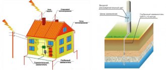
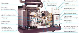
Disabling the live parts of a powerful electrical installation, a transformer or a fragment of a power line does not guarantee full protection of people working on individual elements of electrical systems from injury. Unintended induced or high voltage may occur in an area that is disconnected from the power supply. To eliminate the impact of unforeseen factors on people, an additional means of protection is used - portable grounding, which does not allow voltage levels dangerous to humans to appear beyond the area of its installation.
The function of a portable grounding system is to reduce randomly directed or sudden voltage due to someone else's error to zero values.
Essentially, this protective measure causes a short circuit to the grounded or shorted path. In addition, after the protection is triggered, the voltage source is automatically turned off. Excessive frivolity regarding the use of a portable grounding device, neglect of its installation, use of low-quality products, and violation of operating rules often led to disastrous consequences and even fatal injuries.
Portable grounding is a means of collective protection against damage from randomly directed, suddenly occurring current.
Device
There are two main options for using PP. The first option is intended for use in switchgears, and the second - on overhead power lines. Grounding can be made in single-phase or three-phase design.
The PZ can be made in three design variations: rod, rod with a metal link (ZPL-10) and rodless (ZPP-15).
Portable grounding type ZLP-10
The design of the product consists of the following elements:
- flexible conductor (copper or aluminum);
- fastening clips;
- tips (clamps);
- dielectric rod.
The rodless design of the PZ is usually used for use in complete switchgears.
Example of a rodless PZ design
To simultaneously short-circuit three phases through a single grounding conductor, a three-phase grounding conductor is used.
Single-phase version of portable grounding is intended for separate connection of phases to the grounding loop. Used on power lines with a voltage level of more than 110 kV. This is due to the significant distance from the grounding bus to the phase wires and the phase-to-phase span.
The flexible conductor may be coated with transparent insulation. It can be made of aluminum or copper wires. Using clamps, the PZ is attached to live parts and to the ground loop. The device of phase clamps can be made in the form of clamps and copper tips. The clamps are tightened using an insulating rod, with the help of which the minimum permissible distance to live parts is achieved.
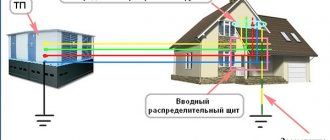
Protection for work on distribution installations ↑
Damages caused by voltage induced from neighboring circuits or erroneously supplied to switchgears will help eliminate portable grounding systems that differ in the specifics of installation in the switchgear. Installation of phase clamps can be done on cylindrical or ball tips, on conductive busbars or at the points where fuses are located. Structurally, all devices are identical; the installation location is regulated by the purpose of the work and the maintenance features of a particular electrical installation.
Requirements
There are many requirements for portable grounding systems. Among the main ones, thermal and dynamic stability with respect to short circuit currents stands out. The design of products should ensure ease of use.
The shorting conductors must withstand environmental influences ranging from -45 to +45 degrees. The cross-sections of the grounding conductors must correspond to the voltage levels. In electrical installations up to 1 kV, 16 square millimeters are used, and at voltages above 1 kV - 25. At a voltage level of more than six kilovolts, the cross-section of the conductors can reach one hundred and twenty square millimeters.
If there are different voltage levels in electrical installations, it is permitted to use portable grounding with the largest required cross-section to service all electrical equipment.
The product package must include technical documentation. The clamp can be fastened to the conductor cores by bolting, welding, pressing or using pressure plates. The clamp must ensure reliable contact at the application site. Insulating structures must be made of dielectric materials.
It is prohibited to use protective shells on conductive elements of the ground electrode, which interfere with visual inspection of their integrity. To insulate wires, it is allowed to use only a transparent sheath.
List of requirements for protective systems ↑
Reliable in use, not causing inconvenience in installation, creating an impenetrable barrier to risks, portable equipment meets the following requirements:
- Impeccable dynamic strength. The clamps should not break under the force of electricians. Thermal resistance to short circuit current caused by grounding. The elements of the device should not burn, melt, or overheat from exposure to ultra-high temperatures, otherwise high voltage will arise at the burnt and melted ends.
Conductor connections in portable grounding systems are made by welding or crimping.
If the conductors were connected using bolts, the fastening is duplicated with hard solder for strength. Groundings with soldering without additional fixing elements are not allowed to be used, since the solder may melt. For the same reason, implying overheating during a short circuit, copper wires of portable grounding do not have insulation.
Portable grounding devices use copper wires without insulation, since the insulation can melt at extremely high temperatures
Calculation of cross-section for PZ
The minimum cross-section of the grounding conductor is determined by the formula:
Smin = (Ik.z.*√t)/C
- I short circuit – maximum current value during a short circuit;
- √t – the longest response time of the main protective devices to disconnect a short circuit;
- C is the calculated coefficient, which reflects the change in the resistance of the material under the influence of heat.
The longest time to disconnect a short circuit is taken to be the total value of the following indicators:
- activation time of the main protection;
- response time of automatic restart (reclose);
- duration of machine shutdown.
The calculated value of I short circuit depends on the type of neutral of the electrical network. With a grounded neutral, the value of single-phase short circuit current is used, with an isolated neutral - three-phase.
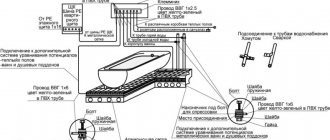
Purposes of wire markings
This process can significantly simplify electrical installation work, planned or emergency repairs, and maintenance of facilities and cable lines during operation. Another functional purpose is to reduce the likelihood of emergency situations and accompanying injuries to working personnel.
The cable is marked during the manufacturing process. The manufacturer must choose the color for the insulating sheath of the wire in accordance with international or domestic standards specified in PUE, PTEEP, GOSTs and other documentation. The data displayed on the outer sheath of the cable indicates information on several parameters:
- number of wires;
- cross-sectional area of the entire cable;
- insulating materials used;
- wire materials, etc.
Such marking, although necessary, is not sufficient to increase safety during the operation of cable lines. Based on it, maintenance specialists will not be able to draw clear conclusions about the purpose of the entire system or a specific section of electrical wiring. Therefore, when performing electrical installation work, additional abbreviations are applied to the cable, adding information about the purpose of the circuit to the characteristics.
Installation and removal of portable grounding
The process of applying and removing grounding is identical for all voltage levels. There are differences only in the number of people performing these operations. In electrical installations up to 1 kV, installation and removal of the ground electrode is carried out individually, and at voltages above 1 kV, the procedure is performed by two people. One person acts as a controller, and the second is an executor.
Process of installation and installation of PZ
Sequence of actions when installing the software:
- Make sure the integrity of the installed grounding;
- Check that there is no voltage at the electrical installation that must be grounded;
- Connect the clamp PZ to the ground loop;
- Place grounding conductors on current-carrying elements.
Operations for removing portable grounding are carried out in the reverse order. All actions must be carried out using dielectric gloves and rods, as well as personal protective equipment. In electrical installations up to 1 kV, only insulating gloves may be used. When the voltage of current-carrying elements is more than 1000 V, the simultaneous use of gloves and rods is required.
Checking the absence of voltage in a section of the distribution installation is carried out with a voltage indicator.
Parallel installation of portable ground electrodes in an electrical network with a voltage of more than six thousand volts is allowed. This is due to the fact that the required wire cross-sections reach significant values. And it leads to an increase in the mass and size of the PZ, which entails difficulties in their operation.
How to maintain a normal frequency of checking equipment grounding?
To completely eliminate problems associated with the operation of the installation, you need to use the services of an electrical laboratory. Thanks to this, the logbook for checking the grounding of electrical equipment will always be completed within the required time frame, as well as in compliance with the basic existing requirements. It is also worth noting the possibility of issuing protocols, without which it is impossible to obtain permits.
Our company can provide you with advice on all issues, including the frequency of checking equipment grounding, as well as the methodology for performing this type of work. Plus, we guarantee extremely accurate results that will truly tell you whether your installation is safe, not just help you bypass the bureaucratic hurdles of obtaining permits.
Example of a technical report for non-residential premises
Back
Forward
Below you can use the online calculator to calculate the cost of electrical laboratory services.
Tests
To confirm compliance with GOST requirements, portable grounding systems are subjected to the following types of tests:
- acceptance (during the initial check for compliance with established standards);
- periodic (permissible once every five years);
- standard (with design changes).
Portable groundings are considered suitable for use if the following measures are successfully completed:
1. Visual inspection of the integrity of all structural elements.
Includes inspection of clamps, conductor cores, insulating rod, restrictive ring on the rod, anti-corrosion coating, protective insulation and technical documentation.
2. Climatic tests.
The procedure is carried out at negative and positive temperatures. Its value should reach forty-five degrees Celsius, respectively, below and above zero. Portable grounding is exposed to temperature for two hours. If there are no signs of destruction of the protective insulation and plastic elements, the product is considered suitable for use.
3. Determination of the mechanical strength of rods.
This experiment is intended to measure the bending of the PZ rod. The permissible deflection deviation is ten percent relative to the insulating length of the rod used for electrical installations with voltages up to 220 kV. For higher voltage levels, a twenty percent deviation is allowed.
To carry out the test, the rod is fixed in a horizontal plane. Securing the end of the rod and the place where the restrictive ring fits. Use a metal ruler to set the level of the rod axis. And according to it, the amount of deflection is calculated.
4. Checking the cross-section of the cores.
To establish the actual cross-section of the portable grounding, it is disassembled into strands. Their number is recorded and the number of conductors in one strand is counted. The diameter of the conductor is measured to determine its cross-section. The resulting calculated value is multiplied by the number of conductors in the strand and by the number of strands.
5. Measurement of thermal and dynamic resistance.
The experiment consists of passing through the finished product the appropriate value of short circuit current from laboratory current sources. The current flow continues until the prototype is completely destroyed. If within three seconds no mechanical damage or cores being thrown from the installation sites were observed, then the sample satisfies thermal and dynamic resistance.
6. Determination of the level of contact resistance.
A microohmmeter is used to measure the resistance at the point where the conductors are connected to the clamp. This indicator should not exceed 600 μOhm.
7. Electrical checks of insulating elements.
The insulating parts of portable grounding are subjected to high-voltage tests.
During operation, mechanical tests of grounding wires are not performed. Rods with metal elements are subject to electrical testing. This procedure is performed every two years.
The product is removed from service if the following defects are found:
- disruption of the connection between the clamp and the conductor;
- traces of metal melting or destruction of grounding conductors;
- the presence of more than five percent breakage of conductor cores.
What are they made from?
The main materials for creating portable grounding are copper and aluminum. Aluminum is quite rare, as it cannot always withstand high loads, and is more expensive. Most often, the conductive part is made of copper wires. The wire itself is not always equipped with insulation. The insulated conductor has a transparent shell. During testing, this point is checked, since the insulation may prevent detection of a wire break.
In order for the device to be secured to an electrical appliance, there are special clamps at the end of each wire. Clamps of this design allow you to securely fix the insulation.
In order to be able to secure the grounding using clamps, you need an insulating rod and a special eyelet on the clamp. It is possible to use another design with a lamb, but it is much less common.
Wires should never be connected using twists. To ensure reliable contact between them and the clamps, the connection is made using crimping, welding or bolted connections.
Attention! Do not solder wires intended for grounding.
The importance of application timing
Any items have their own service life, for example, for portable grounding they are no more than 8 years, according to GOST requirements. The need to comply with the deadlines for testing portable groundings is explained quite simply. If you do not adhere to them, the risk of danger during work will increase. The equipment must be in good condition, which must be checked regularly.
If portable structures malfunction, they are replaced. Compliance with operational deadlines helps to avoid many problems that may be associated with dilapidated structures. Replacement is carried out if, as a result of tests, it is discovered that more than 5% of the wires are broken, or the wires are melted, or the strength of the contacts is compromised.
Standard requirements
Checking portable groundings should be carried out regularly, but the timing is regulated by regulations. The standards insist on a testing frequency of at least once every six months. In addition, GOST requires external inspection of portable grounding systems at least two more times in the same time period. Research is carried out more often if grounding is used for medical devices, devices used to restore health, or conduct special therapy.
The same requirements apply to other devices that affect the functioning of the human body or are used for a long time. This rule also applies to sources of increased danger. If you plan to transfer the grounding to another device and connect it to a new circuit, the portable grounding tests will need to be carried out again. When moving the grounding, the terms are calculated anew. The only exception is the general service life.
Once the device is connected to the new circuit, quality data will be collected and a thorough visual inspection will be required to help identify mechanical damage.
When using a system with a solidly grounded neutral, not only it, but also the phase-zero circuit is checked.
Equipment and markings
Depending on the design of the product, the kit includes:
- portable grounding, assembled or disassembled;
- insulating rods;
- covers;
- technical certificate.
All portable grounding connections must be marked. Which reflects the following information:
- trademark or name of the enterprise that produced the PZ;
- release date and product type;
- core section;
- operating voltage level.
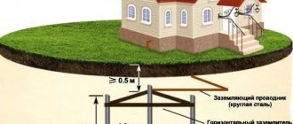
Requirements for grounding locations ↑
According to technical regulations, the installation of portable grounding is carried out on elements of all phases of an area completely disconnected from the power supply. Disconnection is performed at all connection points from which voltage could be supplied, also taking into account reverse transformation.
One grounding is applied on each side, which is a sufficient condition for ensuring electrical safety. It is possible to separate a section from live parts using disconnectors, circuit breakers, circuit breakers, or by removing fuses.
There must be a visible gap between the places where portable grounding is applied, separating devices from live parts with unrelieved voltage. The distance between live components that remain energized and the work site must ensure safety.
Installation of portable grounding connections in closed distribution systems is carried out on live parts in places intended for the location of this particular safety device. They are cleared of paint, and the outline is marked with black stripes.
Note. Places cleared of paint intended for connecting portable grounding systems to protective wiring must be adapted to fix the device clamp or equipped with clamps.
Fastening element for portable grounding - clamp
If portable grounding cannot be applied in electrical installations for compelling design reasons, additional important measures must be taken to increase safety criteria. You can prevent accidental or erroneous supply of voltage by protecting the upper contacts or knives with hard insulating pads, rubber caps, or by locking the disconnector drive device with a padlock.
Alphanumeric designations
GOST specifies regulations for marking the external insulation of cable lines, thanks to which cords, cables and wires can be distinguished from each other. If there are no markings on the braid or they are not sufficient for maintenance and safety, then special tags with additional data are attached to the route.
According to the rules and recommendations prescribed in GOST, a wire is a product consisting of one or more cores, which are protected with insulation along their entire length. The cores can be produced without insulation. A cable is defined as several conductors insulated separately from each other, placed under a single sealed sheath made of metal or polymer materials. A cord consists of two or more flexible conductors that are connected together by twisting or braiding. The cores are fixed along their entire length, and the braid is made from non-metallic materials.
Portable grounding for overhead lines ZPL-10/Z (with indicators UVNBU-6÷35, UVNBU-1)
Standing apart from the range of protection devices of different designs for overhead lines are portable grounding devices of the ZPL-10/Z type. Their special status is due to the fact that they are intended for grounding overhead line wires with a voltage of 6-10 kV directly from the ground surface, that is, lifting onto a support or structure is not required. Next, we must say about one more feature of such PZs - they are supplied complete with high voltage indicators of the type UVNBU-6-35 or UVNBU-6-35-0.4. Immediately before installing the grounding of the high-voltage wire, the absence of voltage is checked using these indicators, which ensures additional safety during this work. The total length of the composite insulating and telescopic working rod is more than 8 m with a grounding conductor cross-section of 25 mm2, according to the standard.
Voltage indicators allow you to check its presence both through direct contact and at a distance from the wire through the indication of the presence of an electric field of a certain magnitude around it. In this case, light and sound signals of a certain frequency, sound intensity and tonality are initiated. To carry out a voltage test, the delivery set includes special universal rods. The UVNBU is powered from an autonomous battery source; there is a mode for checking the functionality of the non-contact voltage indicator.
Technical characteristics of portable grounding for overhead lines ZPL 10/3
| Grounding type: | ZPL-10/Z with UVNBU-6÷35 | ZPL-10/Z with UVNBU-6÷35 and 0.4 |
| Rated operating voltage, kV | from 6 to 10 | 6÷10 and 0.4 |
| Total length of the grounding rod, mm, not less | 3200 | |
| Number of grounding rods, pcs. | 2 | |
| Ground rod type | telescopic | |
| Ground Clamp Type | gravitational | |
| Length of phase wires, mm, not less | 4000 | |
| Length of grounding descent, mm, not less | 4000 | |
| Length of grounding pin, mm, not less | 620 | |
| Wire cross-section, mm2, not less | 25 | |
| Thermal resistance current, kA/3 s, not less | 4 | |
| Total length of insulating rod, mm, not less | 4900 | |
| Number of insulating rod links, pcs. | 23 | |
| Length of insulating part, mm, not less | 2000 | |
| Handle length, mm, not less | 2600 | |
| Operating conditions: temperature, °C humidity at a temperature of 25 °C, % | -30 to +40 to 80 | |
| Weight, kg, no more: | ||
| — grounding rod with clamp | 13,6 | |
| - insulating rod | 2,9 | |
| — grounding assembly | 16,5 | |
| Service life, years, not less | 2 |
Portable grounding for overhead lines ZPL-10/Z (with indicator UVNBU-1)
UVNBU-1 portable grounding indicator for overhead lines ZPL-10/Z