Lightning protection systems should be checked for functionality from time to time. The need for such tests is dictated by ensuring the safety of both the building and the people in it. In addition, lightning rods are under constant negative influence of environmental factors, which can lead to a deterioration in their functionality.
Checking lightning protection is an important event that is carried out as planned or unscheduled if there are doubts about the operability of the system.
Types and frequency of inspections
Verification activities are usually divided into types:
- Scheduled inspection (another name is seasonal). Conducted according to a predetermined schedule.
- Extraordinary inspection. Carried out in the event of unforeseen events (for example, system failure).
- Start-up and introductory testing of protection.
Scheduled tests
The procedure for conducting scheduled testing is regulated by the standards established in instructions RD-34.22.121-87. Inspections are regulated by the provisions of the PUE (rules for the construction of electrical installations) and PTEEP (rules for the technical operation of consumer electrical installations). For outdoor protective devices, the rules are specified in paragraph 1.14 of RD-34.22.121-87.
In accordance with these standards, all protected objects are divided into categories. Based on the category established for the building or structure, the frequency of inspection of the lightning protection system is established. For example, for buildings of the first and second categories, tests should be carried out every year before the onset of thunderstorm season. The third category concerns objects exposed to minor danger. In this case, inspections should be carried out every three years.
Extraordinary tests
Inspections outside the planned schedule are carried out in the following cases:
- Making any changes to structural elements that were not initially included in the design documentation.
- Upon completion of repair work and reconstruction of the building.
- In the event of major accidents, catastrophes or natural disasters.
Start-up and introductory tests
They are carried out upon delivery of the protected building to the customer. Start-up testing is carried out immediately after completion of the main construction work or according to a previously agreed schedule for the reconstruction of the facility.
The results of the inspection are documented. Based on the conclusion, operation of the system begins.
Test facilities and equipment
The list of necessary testing tools and equipment is determined by the permitter together with the manufacturer of the work. In general, a set of devices, tools, and protective equipment should include the following:
- assembly line safety belts, safety ropes, safety helmets, ladders;
- device MRU-101
- hammer (weight 400 gr.)
- calipers
- tape measure 3 m
Safe working practices
Work on checking lightning protection systems of buildings is carried out according to a permit or by order. The type of work registration is determined by the employee who has the right to issue orders and orders. Persons from electrical technical personnel who are at least 18 years old, trained and certified in knowledge of safety regulations, PTEEP and this technique, provided with tools, personal protective equipment, and special clothing are allowed to work.
The team must consist of at least two people:
- a work performer with an electrical safety group of at least III
- a member of a team with an electrical safety group of at least III
These persons must undergo a medical examination for admission to steeplejack work and a knowledge test of SNiP 12-03-99 in the scope of the safety requirements for steeplejack work. A special entry is made about permission to carry out steeplejack work in the knowledge test log and in the certificate of verification of values on the page “Certificate for the right to carry out special work.”
Based on the measurement results, a protocol of the established form is drawn up. Persons who have committed violations of safety regulations or PTEEP, as well as those who have distorted the reliability and accuracy of measurements, are liable in accordance with the legislation and regulations on the mobile electrical laboratory.
Stages of inspections
The task of scheduled, introductory and extraordinary resistance measurements and checks of lightning protection devices according to other parameters is to assess the compliance of the existing parameters with the regulations and design documents. For this purpose, the quality of installation work is examined, the condition of local sections of the system and contacts is determined. The goals of testing, the content and scope of tasks depend on the parameters of the object and the design features of the protection system.
Tests are carried out according to a certain algorithm:
- Compare the data available in the design documentation with real indicators.
- They check the compliance of protective zones and structures with the requirements of regulatory documents.
- Inspect protective devices, down conductors, and connecting contacts to check their integrity, the absence of traces of rust, and the quality of installation connections.
- Welds are checked for integrity and strength by applying mechanical forces (tapping with a hammer).
- Measure the resistance of bolted joints.
Measurements of the grounding resistance coefficient of lightning rods are carried out separately for each device. The final indicator should differ no more than five times from the data obtained during the introductory tests. If the grounding conductor performs a related task (working grounding conductor of the building and lightning protection system), there is no need for resistance measurements.
To obtain the most accurate results, planned and start-up testing work is carried out during the lowest level of moisture in the soil adjacent to the building. In regions belonging to permafrost zones, measurements are carried out during the period of maximum freezing of the ground.
Note! When testing the system, the level of atmospheric pressure is taken into account. This parameter is secondary, but is included in the final protocol.
Lightning protection systems are tested:
- before putting them into operation
- for buildings and structures of protection category I and II at least once a year
- for buildings and structures of protection category III at least once every 3 years
At the same time, monitoring of the transient resistance of bolted connections of lightning protection systems should be carried out annually with the beginning of the thunderstorm season.
Lightning protection devices for buildings and structures must be tested, accepted and put into operation before finishing work begins.
Measuring equipment
High-precision equipment type M-416 is used for testing. The device is used in conjunction with a data meter for electrical safety of equipment and electrical installations (MPI-511). At the same time, existing standards allow the use of other measuring instruments with similar capabilities.
The resistance of the functional elements of the protective system is measured with the MRU-101 device. The device is capable of automatically stopping the test when emergency situations occur and displays the following indicators on the monitor:
- Overcoming 24V noise level (LIMIT and UN).
- Noise voltage exceeds 40B (LIMIT and OFL).
- No current current (-r- and test socket icon).
- The resistance level of the measuring probes is too high - over 50 kOhm (LIMIT and indicator on the probe).
- The meters exceed the standard range (OFL).
The noise voltage indicator is set by pressing the R button or by selecting the measurement function by turning the device switch.
The received data is not considered correct if the equipment has detected the following situations:
- Deviation of the resistance level of the probes by 30% (LIMIT).
- The battery is in a discharged state (BAT).
If there are no grounds for blocking or slight deviations of the input data from the standards, MTU-101 takes measurements and displays the following data:
- The amount of resistance in a given area.
- Probe resistance.
- Soil resistivity.
- Other indicators (for more information, press the SEL button).
Note! The measurement range for each parameter is determined automatically by the equipment.
Measuring instruments
The installation quality of the lightning protection system is checked using special measuring equipment. This category includes both manually adjusted and automatically adjusted measuring equipment. In this area, priority is given to modern automatic meters, while manual devices are considered less reliable and outdated technology.
Among the self-tuning meters used for testing lightning protection systems, the most used is the MRU-101 device. It can be used to control resistivity, grounding resistance parameters, as well as characteristics such as spreading current. The device can store hundreds of measurement indicators in memory and selects a range that includes the desired settings.
The obvious advantages of this device include the indication of a potential error in the readings - in such a situation it gives a special signal. In addition, using the MRU-101, you can constantly monitor measurement conditions and noise levels: if an obvious error is detected, the measurement process will stop completely.
Operation of the device. The most common test method choice with the MRU-101 is the 3-pole circuit. In this case, three probes are driven into the ground in the area where the grounding components are located at a distance of up to 20 meters from each other. Then the working inputs of the device (E, H and S) are connected to the probes.
Another, more accurate method is to use a 4-pole circuit. Its difference from the above-described circuit is the connection of the electrode connected to the input marked “E” to the input wire marked “ES”.
Non-contact measurement technology. Measurements using MRU-101 can also be carried out non-contactly - for this purpose, special pliers are used, which are supplied with the device. Before use, the clamps are calibrated and then connected to the fifth input.
Three-pole measuring system
For measuring the resistance of a lightning protection system, the method is considered basic. The work is carried out as follows:
- The ground electrode is connected to the measuring socket of the equipment.
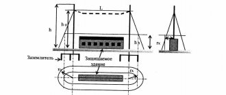
- The current probe is directed into the ground. The measurement is carried out at a distance of over 40 meters from the protective system. The probe is connected with a special conductor to the socket of the device called “H”.
- The potential probe is installed in the ground at a distance of more than 20 meters from the protective system being studied. Next, the probe is connected to the measuring socket marked with the letter S.
- The probes and the ground electrode are lined up in a single line.
The rotary switch is placed in position RE 3p. Next, measurements begin after pressing the START key.
After the procedure is completed, the ground resistance indicator (RE) and the data obtained from the probes appear on the monitor. The distance between the potential probe and the protective system is reduced to one meter. Then they take another measurement. If the results differ by more than 3%, the current probe is moved further away. The measurement is carried out repeatedly until an acceptable ratio of the obtained data is obtained.
Measurements using a three-pole circuit involve taking into account several nuances. For example, with increased resistance of the probes, this indicator for grounding is set with a certain error. The same should be said about measurements of the resistance of the ground loop, which is in free contact with the ground. The reason for the existing errors is the excessively high ratio of the resistance of the probes and the ground electrode.
To improve the accuracy of the data obtained, it is necessary to achieve better contact of the probes with the ground. For this purpose, the probes are moved to another, more humid place. An alternative to this solution is to artificially moisten the soil before performing the test. In addition, you need to inspect the measuring conductors to ensure the integrity of the insulating material, the absence of traces of rust, and check the contacts with the probe terminals.
Note! The results of all additional procedures are recorded in the final protocol.
Compliance with all recommended conditions allows you to obtain fairly accurate results (taking into account the general measurement error). It should be borne in mind that a correct assessment of the influence of the resistance of the probes requires additional calculations.
Ground resistance
When measuring ground resistance for electrical installations, power frequency current is usually used. But when carrying out measurements for grounding lightning protection, the situation is fundamentally different. Measuring resistance for a short powerful pulse gives different results from measuring with alternating current. At the same time, the pulse method is closer to the real situation that occurs during a lightning strike. Numerous experiments have shown that the higher the current during pulsed action, the lower the soil resistance. In turn, we cannot predict in advance how strong a lightning strike will be. In addition, the duration of the pulse front has a greater influence on the accuracy of simulating real conditions during a lightning strike than the current value.
It can be concluded that it is permissible to measure grounding resistance using the pulse method at a current that is significantly lower than what occurs during a real lightning strike. In practice, pulses with currents of up to 1 A are used. But the measuring device must necessarily produce a pulse with a rise time that lies within this parameter for real conditions. The corresponding values of the pulse front duration are given in SO 153-34.21.122-2003. As a result of carrying out measurements using this technique, we obtain a slightly higher value of grounding resistance than with a real lightning strike, due to the lower current. That is, measuring at a lower current actually places more stringent requirements on grounding compared to testing with a generator that fully simulates a lightning strike.
Four-pole measurements
If particularly high accuracy of results is required, errors must be eliminated. Using a four-pole circuit will help in this matter.
Measurements are carried out as follows:
- The receiver is connected to the equipment sockets marked E and ES.
- Both probes are installed in the same way as in the three-pole method.
- The rotary switch is directed to position RE 4p.
- Press the START button.
- Record the obtained data on the grounding resistance and probes (Rs and RH). The data is displayed on the monitor.
The measuring probe is moved one meter from the protective system. After this, measurements are made again. The results obtained are interpreted in the same way as in the case of using a three-pole system. At the end of the study, the data is entered into the final protocol.
Note! Regardless of the scheme used, the norm is considered to be a distance of the potential probe to a value equal to 62% of the distance between the system under study and the current probe.
Special requirements for testing lightning protection
In order to get accurate readings, you need to be clear about when to measure. Experts recommend choosing special periods for each season. In summer, you should wait for severe drought, when the ground increases resistance, losing all moisture. In winter, a similar phenomenon is observed if the soil freezes to a depth of more than 0.5 meters. If this does not happen in your climate zone, the lightning protection test is carried out on the coldest day of the year.
For power lines, an additional measurement is carried out, which occurs at the beginning of the thunderstorm season - accordingly, this period falls in April-May, depending on the region.
If the study is carried out on dates different from those indicated, a table of correction factors should be used. Below you can use the online calculator to calculate the cost of electrical laboratory services.
Documenting results
The main document indicating the reliability of the data obtained is the test report of the protective system. This document shows all the required performance characteristics. Separate paragraphs indicate the results of the measurements obtained and indicate the test conditions.
During introductory testing, working passports are issued. When the tests are completed, the owner of the object or his authorized representative is given documents indicating the results of the test.
Checking the lightning protection system is a critically important activity. The lives of people and the safety of material assets depend on how well the work is done. To carry out the inspection, it is recommended to contact reliable service providers who specialize in this type of work and have a good reputation.
Testing power tools: frequency of testing at home
Construction and other work cannot be done without power tools. To ensure they are safe to use, they should be tested regularly. Timely diagnostics of power tools reduces the risk of short circuits and extends the life of devices.
Before starting work, tools must be tested
Why comply with the test deadlines?
Using a faulty electrical appliance may result in short circuits and electrical injury. Therefore, it is important to observe periodic inspections of power tools. Timely procedures ensure compliance with the following provisions:
- checking the technical safety of the device before use;
- timely elimination of breakdowns and increasing the service life of the tool;
- compliance with all rules for operating the device;
- timely prevention of equipment breakdowns.
Minor damage to the instrument can lead to serious damage if not repaired promptly. You also need to know that regular elimination of defects can increase the life of devices both in production and at home. Therefore, it is very important to know what the frequency of inspection of power tools is, and not to ignore these measures.
Note! The device should be tested not only during its use, but also after purchase.
Timely inspection extends the service life of devices
Frequency of checking the characteristics of electrical tools
When using devices in everyday life and at the enterprise, it is not enough to know how often the power tool is tested. It is important to have information about the classification and features. For household purposes, a tool is used that has sufficient insulation and in rare cases causes injury. However, large enterprises use different types of electrical equipment.
Therefore, it is necessary to pay attention to the following characteristics:
- 0 – insulation is provided without connection to the grounding device;
- 01 – provides working type insulation and a grounding device;
- 1 – working insulation is provided, but grounding is built into the network connection cord;
- 2 – has double protection;
- 3 – there is no grounding, since the device is designed only for a voltage of no more than 42 Volts.
Each production facility must regularly monitor the frequency of inspection of power tools and maintain relevant documents. If used frequently, the power tool should be inspected every 10 days. Installation tools are tested every 6 months. Devices that are used under voltage are checked once every 1 year.
Important! According to labor safety regulations, it is prohibited to use a faulty tool for work. It is also prohibited to use a device on which the previous check has expired.
The frequency of testing may depend on the classification of the tool
Who is authorized to carry out measurements and tests
Testing of electrical equipment must be carried out by specially trained personnel who have completed the necessary training and have an electrical safety group. In domestic conditions, it is necessary to contact an organization that conducts inspections of electrical appliances.
After checking the power tool, all information must be recorded in the inspection log. In it, the specialist indicates the name and date of the procedure. Enterprises also indicate the device inventory number and the recommended date for the next test.
A protocol is also generated, which indicates the purpose and method of verification. Such methods are necessary for the safety of workers and are mandatory.
Checking and testing power tools at home
In domestic conditions, it is also important to know how often the power tools used are checked. It is especially important to test devices that are portable. Each device has detailed inspection instructions.
Before starting work, the tool must be visually inspected
Basic principles of electrical tool inspections
In order to confirm the serviceability of a power tool, two types of examination can be used: checking and verification. Each of these events has its own characteristics that you need to know.
- Verification. This procedure can only be carried out by specialists who have undergone appropriate training. The verification procedure is approved in regulatory documents. Most often, this type of examination is carried out in special laboratories. Auxiliary devices are used for analysis.
- Examination. The power tool is inspected externally for damage and chips. It is recommended to carry out this test every 10 days.
Before starting the testing procedures, it is necessary to clean the instruments from dust and possible contaminants. Traces of oil are also removed from devices.
Note! If the device does not have a tag with a test mark, it must be tested without first being turned on.
External inspection and checking idle speed
Inspection of a portable tool can be carried out by each user independently. In order to hold the event, the following recommendations must be followed:
- Carefully inspect the integrity of the case - there should be no chips or damage on it.
- Check the fastenings of the cutting parts: they should all be securely fixed and not move under light load.
- The gear shift buttons should work properly without jamming.
- Turn on the device and check idle operation. The sound of the device should not be intermittent and contain no extraneous noise.
- There should be no open areas with wires on the cord. If any, they must be isolated.
- If the device has removable parts, you must ensure that they are securely attached.
- The power cable must be inspected for kinks. Also, the cord should not have any signs of drying out or cracks. There should be no damage to the insulation where the cord enters the device body.
- The plug must be intact.
To carry out the test, you need to pick up the power receiver, making sure that the cord is not connected to the power supply. Inspect carefully. Inspection is necessary before each use procedure. As a rule, for convenience of examination, a tag is placed on the portable instrument, which indicates the date of inspection.
https://www.youtube.com/watch?v=Uw5eRGM34v4
It is prohibited to use devices with damaged housings.
Insulation resistance measurement
To inspect the integrity of the insulation, a special device is used: a megohmmeter.
After connecting to the device, you must press the power button. For standard devices designed for 220 V, the indicator should exceed 500 KoM. If this indicator is less, using such a device is not recommended. The duration of the check should not exceed 1 minute.
Insulation measurements are carried out using a megohmmeter
It is also recommended to carry out periodic inspection. For these purposes, the tool is given to a specialist.
The instrument expert lowers the device's handle into the water on a special wire. Using two outputs, the wire is connected to transformers and a container of water that has been previously grounded.
10 kV is supplied; with a working device, the final value should not exceed 1 mA.
Checking the functionality of the grounding circuit
To inspect the grounding circuit, it is necessary to use a device such as an ohmmeter. Connect the device to a special connector on the device and turn on the ground. The test results will appear on the device, which should not exceed 0.5 Ohm.
Important! If this indicator is higher, the device is unsafe for further use.
Inspecting electrical portable equipment is an important process that should not be ignored. Correcting defects in a timely manner allows you to avoid future injuries and serious damage. Therefore, it is important to know what the frequency of inspection of power tools is and how to carry out the inspection correctly.
Electrical laboratory services
Despite the relatively low probability of being used for its “direct” purpose at most facilities, the lightning protection system is included in the list of special responsibility, since not only the integrity of expensive equipment or building structures, but also human lives, as a rule, depend on its performance.
Therefore, it is better to entrust the creation and maintenance of such systems to professionals - a licensed electrical laboratory with qualified personnel using certified electrical measuring instruments. One of these professional organizations is the electrical engineering laboratory (ETL) "Mega.ru", which provides a wide range of services to organizations and individuals in Moscow, the Moscow region, as well as surrounding areas.
You can order work, get advice or clarify details of cooperation by calling the phone numbers and e-mails published on the “Contacts” page, or simply using the feedback form in the side column of the site.
Measures to maintain performance
Based on the results of the inspection, a protocol and a list of defects are drawn up. They include data on all deficiencies and identified deficiencies. Faults that interfere with the operation of lightning protection must be corrected as quickly as possible.
Faulty parts, as well as grounding elements whose cross-sectional area has decreased by more than 25% due to corrosion, must be replaced. To prevent corrosion, anti-corrosion agents should be regularly applied to the lightning rod elements that require such treatment. Such means, in particular, are suitable paints and varnishes.