Description
The Sonoff basic version relay switch allows you to control electrical appliances using a mobile phone. This is achieved by connecting the internal Wi-Fi module of the relay to the home router and providing the router with Sonoff access to the global network.
Sonoff Basic is a compact device that can be easily placed:
- Behind the ceiling;
- In a brick niche;
- In the bowl of a chandelier;
- Inside the lamp.
The kit includes 2 protective caps and screws for fastening during installation.
Peculiarities
The device is equipped with remote sensors AM2301 or DS18B20, while the latter is intended only for measuring temperature indicators. The DS sensor is waterproof and can be submerged in water. AM includes 2 sensors, which are housed in a plastic housing.
At the top of the case there is a groove for attaching the relay, at the bottom there is a connector through which the device is connected to the mains. Self-clamping terminals are used to install wires. On the front there is a manual control button, and on the side there is a place for connecting sensors.
The device is built on the basis of ESP8266, which allows you to flash alternative firmware into it and, accordingly, use it with alternative software.
Types of models
The manufacturer offers a choice of models from the Sonoff World On series. There is a difference between them and it lies in the method of use:
- Sonoff World On (basic version) is suitable for controlling home appliances such as lamp, chandelier, CCTV camera, freezer.
- Sonoff World On RF is the same relay in the basic version, but comes with one control panel. This solution is well suited for controlling gates or raising barriers.
- Sonoff World On TH is equipped with sensors for measuring temperature and humidity, so the gadget is recommended for use in a greenhouse, next to a boiler or air conditioner.
- Sonoff World On Duo, 4CH and 4CH PRO - work with 2 or 4 devices simultaneously. More suitable for industrial applications.
We recommend reading: review and instructions for using the 4-channel version of the Sonoff 4CH Pro relay.
The type of connection to the device and pairing with a mobile phone is generally similar, so the article discusses further interaction with the simplest relay model.
Buy a Smart Home in Minsk..in the Republic of Belarus
- Light sensor PL111
- RUB 49.92
- PL111 is a light sensor designed to work as part of the nooLite system with all power units.
- Controller PRF-64
- RUB 295.68
- The nooLite PRF-64 controller is designed to control and display information from nooLite and nooLite-F devices through the “nooLite Home Control” mobile application.
Power block SRF-1-1000-R
RUR 89.52
Designed to control roller shutters, curtains, blinds, gates. Has feedback and encryption. Compatible with nooLite system (no feedback). Power 1000 W
- Touch control panel PU411 beige (4 control channels)
- 42.72 rub.
- The nooLite PU411 remote control radio transmitter is designed to control lighting devices and other loads connected through nooLite power units: on/off, power adjustment, recording and calling scenarios.
- Touch control panel PU411 white (4 control channels)
- 42.72 rub.
- The nooLite PU411 remote control radio transmitter is designed to control lighting devices and other loads connected through nooLite power units: on/off, power adjustment, recording and calling scenarios.
- Wi-Fi router EZVIZ Vault Plus
- 420 rub.
- Router with data storage function Wi-Fi speed up to 1200 Mbps Work in 2.4 Hz and 5 Hz networks Wi-Fi within a radius of 100 m, penetrates 3 walls Connect up to 8 EZVIZ cameras Support disk up to 6 TB
- Outdoor camera EZVIZ C3C
- 175 rub.
- Outdoor HD camera with connection via Wi-Fi or Ethernet HD 720p Viewing angle 114° Wi-Fi or Ethernet wire Night shooting (30 meters) Dust and moisture protection IP66
- EZVIZ C6T
- 227 rub.
- 360° PTZ camera Full HD 1080p Automatic object tracking Wi-Fi or Ethernet cable Night shooting up to 10 meters Two-way audio communication
- EZVIZ C2W
- 175 rub.
- Home camera with connection via Wi-Fi or Ethernet HD 720p Viewing angle 92° Wi-Fi or Ethernet wire Night shooting up to 10 meters Two-way audio communication
- EZVIZ C2mini
- 175 rub.
- Home Wi-Fi camera with wide viewing angle HD 720p Viewing angle 115° Built-in Wi-Fi Night shooting up to 10 meters Built-in microphone for audio recording
- EZVIZ MiniO
- 140 rub.
- Two-way audio for communication
- Power block SUF-1-300 DIN
- 77 rub.
- A distinctive feature of this model is that the device board is housed in a universal modular housing, 1 module wide, which allows the SUF-1-300 DIN power unit to be mounted both on a plane and in a lighting panel on a DIN rail.
- Remote switch CRCS two-channel with remote control
- 30 rub.
- Remote switch CRCS two-channel with remote control
- SONOFF Smart Wifi socket
- 55 rub.
- Smart Wifi socket SonoFF Control any electrical appliance via the Internet from a smartphone from anywhere in the world!
- SONOFF Smart Remote GPRS/GSM Switch
- 85 rub.
- Remotely turn on/off electrical devices anywhere via GPRS network.
- SONOFF World On TH Wi-Fi relay with temperature and humidity sensors, 16A
- 63 rub.
- SONOFF World On TH Wi-Fi relay with temperature and humidity sensors, 16A.
Specifications
Sonoff Wi-Fi relay has the following characteristics.
| Parameter | Meaning |
| Max current | 10 A |
| Supply voltage | 90–250 V |
| Wi-Fi protocol | 802.11 b/g/n |
| Operating temperatures | 0°C to 40°C |
| Weight | 0.05 kg |
| Dimensions | 88×38×23 mm |
The base of this relay is the Chinese microcontroller ESP8266.
Installation and connection
For the relay to work, it needs 220 V power. From this fact it follows that the automation can be disguised anywhere without difficulty. (on the ceiling itself, walled up under a lighting fixture or decoration, in a switch box, in sight for manual control, etc.).
For surface installation it has 2 mounting holes (on the back). The connection diagram is implemented as follows:
- Terminals L and N on the input side (the designation is indicated directly on the front side of the relay) are supplied with phase and zero from a 220 V supply;
- The cross-section of the connected cores must fit within 1.5 square millimeters. Otherwise, there will be problems with attaching the cores to the terminal blocks.
- At the other end of the wire there should be a plug, which in the future will be connected to a 220 V network.
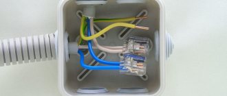
As an example, a power cable of the PVS brand (3 wires - brown, blue, yellow) was used for connection.
Install and tighten using a screwdriver:
- Brown - phase to terminal L.
- Blue - zero to terminal N.
- Leave the yellow one unconnected.
On the reverse side (output) connect the adjustable device in the same way.
After installation, cover the connection area with protective covers. The teeth will allow you to fix the connected wires and protect them from breaking. After installing the cover, tighten it with the mounting screws.
To connect a load of up to 10 A, the relay can be connected according to this scheme.
If the rated current exceeds 10 A, in order not to burn the device, it is recommended to use a contactor in the circuit.
Using the contactor you can control:
- Single-phase and three-phase load;
- Direct and alternating current.
After connecting to the power circuit you can:
- Operate manually;
- Pair your smartphone with the relay and control it via WiFi.
Single-phase WiFi relay eWelink with a stated current of 63A
In the previous review, I talked about a powerful relay with the ability to remotely control via WiFi and other goodies, but then I wrote that there would be a review of another relay, and now I’ve finished testing it and can share the results and conclusions. At a quick glance, it will most likely seem to you that the difference between this and the previous relay is only in price and size, but in fact this is not entirely true, even more likely not at all, however, I will be consistent and start as usual, with packaging and configuration.
Well, everything is the same here, a small box, a relay and instructions for it.
The instructions are all in English, but there are pictures, so in general it’s clear, as before I was interested in the key characteristics: Input voltage range 120-280 volts Switching current - up to 63A Power consumption - no more than 3W
Now in more detail about the relay itself.
Actually, everything is standard, for a standard 35mm rail, one module wide, which, by the way, is very rare given the declared switching current. In the photo, in comparison with standard circuit breakers and the previous relay, by the way, it is noticeable that the circuit breakers are slightly shorter, and the longest of all the relays from the previous review.
1. A pair of LEDs were placed on the front panel, service (WiFi connection, setup) and output activity indication. 2. As you can see from the previous photo, there is an incomprehensible wiring sticking out of the relay, the fact is that in this size of the case it is difficult to fit a full-fledged terminal for connecting the zero (although not unrealistic), and since the current in this circuit is small, it is simply they brought the wiring out. 3. The terminals are the most common, for wires with a cross-section of up to 16mm.kv, I didn’t have such a wire, but 6mm.kv holds perfectly. 4. Output terminal, but I didn’t want to show it, but a hole just below, clearly intended for the wire that was brought out through the slots of the housing. 5. On the side there are instructions for setting up the connection, although it doesn’t make much sense because it’s not visible in the shield anyway. 6. The latch is not spring-loaded, but has two positions, open/closed.
Again, I’m getting ahead of myself and showing the application before its description, excuse me, especially since that’s not what I wanted to say at all. The fact is that here the output activity indicator LED was made correctly; when the output is active, it lights up red; when not, the LED is turned off. In addition, when switching, the application turns on the vibration response, and also changes the background from dark to white (off/on), convenient.
The wattmeter starts at approximately 52-53 volts, but can sometimes behave erratically.
But if you raise the voltage a little higher and everything works fine, there is no such effect as with the previous relay, when it worked but connected to WiFi, there is no such effect here. The accuracy of voltage measurement is, in principle, normal, but it is very difficult to check correctly because there is a large delay in data output. In this case, the relay works interestingly, if the voltage or current changes greatly, then the data is updated quickly, sometimes up to 1 race per second, but if the fluctuations are small, then it can easily be once every half a minute or less.
With current, in general, the situation is about the same, a little worse than with the previous relay, but in general it’s normal.
Even the voltage drop across the terminals is approximately the same, so I would also limit the maximum continuous current to about 40A
As with other devices that have a large limit on the measured current, the test was carried out with a low-voltage transformer and a current clamp.
Here, in principle, it is also normal, although at times, due to the output delay, the difference between the readings of the clamps and the wattmeter was either smaller or greater, the clamps still measure much faster. The photo shows average values.
1. But when the current was raised to the maximum declared, it turned out that the device began to “fail” and instead of the supplied 61.5A it displayed only 54.39A. 2. Reduced to almost 50A, it shows normally. 3. I raise it to 63A as a double check, no, now it generally shows 52A 4. Empirically, I found that a current of about 55A is displayed normally, and everything higher is underestimated.
If you thought that was all, then you are deeply mistaken, and the whole point is that you should have looked not at the current, or rather, not only at the current. 1. I supply 42A, everything is great, current, power. 2. I raise it to 45A, everything is fine with the current, but for some reason the power dropped to 7.7 kW, although it should have risen to 10 kW. 3. Just for fun, I applied 80 and 90A, well, it’s a complete mess here both in terms of current and power...
I didn’t stop there either, but decided to change the phase/zero of the load. As with the previous wattmeter, it turned out that now it began to slightly overestimate the readings, but not fundamentally. The key thing is that this had no effect on the current/power measurement error, although the threshold for correct operation became slightly higher and amounted to about 44A. Moreover, I would like to note that when the load is higher than a certain one, both current and power are displayed as “drunk”, i.e. they sometimes lack a direct connection with the real current.
Of course, I could say that I was so “lucky”, but in the reviews I came across a comment where a person also complained about the problem of measuring power, only for him everything was even worse
The measured values are not accurate; the calculations are incompatible 230v * 0.58A=133.4w, which he writes for 6.3 W
I checked the heating at a load current of about 60-62A, I have no questions here.
Let's move on to the software. Everything is simple here, we find the QR code in the instructions and follow it to the manufacturer’s website, where it is offered to download the software, you can do this simply through the market, the essence does not change, as does the very low rating of the software, only 3.3 points. Next, we go in, register (via phone or email), agree that the manufacturer takes security seriously and will then send out our data to everyone, and proceed to setup.
In general, everything follows approximately the same scenario as with the previous wattmeter, but for some reason the connection took a long time, and the message about a successful connection was issued synchronously with the time I turned off the power to the wattmeter, I thought that everything just froze...
By the way, about “stuck”, how long does it take to “cold” start the software, about 15 seconds, despite the fact that the same Tuya starts in 5.
The settings are also approximately the same, timers, schedule, although there are some differences, for example, there is a black background of the main window when the output is disabled and white when it is enabled.
Also, small numbers for indicating power/current/voltage have climbed here, although to be fair they are still larger here than in Tuya/Smart house, but still, the interface is just as useless, which is no wonder when some people copy from others.
The settings are also largely similar, but there are interesting exceptions, for example: 1. network activity indicator, you can turn off the LEDs on the panel, although for some reason the relay stops responding to on/off commands... 2. State after shutdown, I often set “ last" 3. Turn-off delay, here we set the interval after which the relay will be turned off after turning on, i.e. imitation of a “momentary” switch, i.e. buttons.
There are also various other options, but you will receive some of them only after payment.
The software can keep logs, and in addition allows you to save consumption data in a csv file, although the information there is very brief.
But I was more interested in the security function, where they will first warn you that it is better to read the instructions, and only then they will let you go to the settings. You can set restrictions on minimum/maximum power, as well as voltage and current. For the sake of experiment, I set it to 242 volts.
We apply voltage from the LATR, the output is active, we increase it to 260 volts and after about 1-3 seconds the output turns off, we reduce it back, but the output remains in an inactive state. Perhaps somewhere there is a setting so that the output is activated automatically, but I did not find it. If you try to forcefully turn on the output, nothing will happen, the output will remain inactive and the on/off command will be written to the logs.
Deciding to check further, I closed the software on my smartphone, the relay also turned off normally, I was already happy and tried to turn off WiFi altogether, but here’s the bummer, in this case the protection does not work.
Of course it was interesting to get inside, especially after the oddities with measuring current and power. Alas, there is no easy way of access, so I drill out the sleeves and disassemble them that way.
Inside is a small scarf and a relay, and the relay, judging by the markings, is 60A, i.e. if they had included a reserve, then they would have just gotten a 40-45A relay, which is actually the maximum it can do when measuring. The input terminal is connected to the relay using a wire on which a current-measuring transformer is placed; in fact, this is an important difference from previous devices. The output terminal of the relay is designed so as to also be the output terminal of the device.
To remove the board, you must first remove the button and indicator light guides, and initially the board is crooked in the case. The current-measuring transformer and relay are connected through connectors, a small detail but a nice one.
On top of the board there is a power supply system, and it’s a plus for the manufacturer that he did not install a ballast capacitor. A 1 amp fuse is visible on the left.
There is also a varistor at the input of 470 volts (330 rms), but the trouble is, not only is the filter capacitor set to only 400 volts, but the varistor is also connected before the fuse, well, what if the capacitor suddenly does not trip when the voltage is exceeded...
Below is a WiFi module and a specialized CSE7759B chip specifically designed for electricity metering, what needs to be done to make it work poorly?
But the design of the relay was surprising; the fact is that it is structurally part of the device body, or rather, on the contrary, the device body is the relay body. In general, the solution is interesting and, in my opinion, completely justified. Of course, someone will tell you how to repair it now, and just like others, i.e. no way.
By the way, the relay looks quite normal, I think it can switch its declared 60A, but as I wrote, for a long time it’s more likely to be 40A.
Conclusions. In general, it’s a very ambiguous relay; to begin with, I had a strong assumption that initially it was a 40-amp relay, but then the manufacturer decided that it didn’t sell well and it was necessary to increase the current... by changing the sticker. It turns out that with the declared 63A we have: 1. a relay with a current of 60A 2. but the current can only be measured up to 50-55A 3. but to measure the current so that the power is measured correctly, then no more than 40-42A
In fact, this is a device with a current of up to 40A, everything else is marketing. But even this is not a problem, the absence of a fuse in front of the varistor can add to the impression in case of its breakdown, and to fix this you need to drill out the sleeves, in general darkness. Besides, what’s so difficult about making it possible to work out protection thresholds without connecting to the cloud? After all, this immediately significantly expanded the possibilities.
In total, this could have been a good compact 40A relay if it weren’t for the marketers who indicated the current was 1.5 times higher and the engineers who forgot that the fuse is placed before the varistor, and not after.
Of the advantages, I will note two: 1. price, in my opinion, 20 dollars is more or less normal 2. size, after all, 1 space in the shield is half as much as 2, which most similar devices occupy.
The store threw out a coupon BGb51e5f
with which the price will be $19.99 until March 18, and that’s all for me, I hope that it was useful and, as always, I will be glad to have questions and comments.
The product was provided for writing a review by the store. The review was published in accordance with clause 18 of the Site Rules.
Wi-Fi connection
To fully control and manage Sonoff from your smartphone, you need to install the Ewelink application. It is available for iPhone and Android devices. The software can be found in the Play Market, App Store and using the QR code on the Sonoff box.
After installing the utility, go to it:
- Complete registration, select a country and email (the gadget must have Internet access).
- Find the verification code on your email inbox and enter it to complete registration.
- After entering your password in two fields, complete registration and log in to your profile.
- Next, in the utility, click the “Add device” button.
- To pair a mobile smartphone and a relay, hold the black button on the Sonoff case for about 5 seconds.
- As soon as the LED flashes green, check the box next to the first option and click next.
- From the list, select your home or office Wi-Fi network and enter its SSID and password (check the box next to “remember data”).
- Wait for the smartphone to detect, connect and configure the connection to the relay.
- After successfully registering your device, you can rename it in the application as you wish.
- Then click the “Finish” button.
Reviews
Having read a lot of reviews on the Internet, we can say that people really like the innovation. We hope to soon be able to control everything with the click of a button or using a smartphone. There is a lot of negativity towards the mobile application. But here you need to take into account the fact that this innovation appeared quite recently.
The software is constantly updated, and the developers fix bugs. Dear readers, those who are the proud owners of this device - tell us your impressions. How much more convenient has life become with a WiFi relay connection? It is very interesting to hear feedback first hand.
Source
Remote control
If the Sonoff device is online, the green LED on its body lights up statically. When the LED blinks periodically, it indicates that the connection with the router or the Internet has been lost.
To remotely activate or deactivate the load, in the application, click on the relay icon and click on the large virtual power button in the middle.
The timer function is present, so you can configure the control option based on filters:
- Repeat or once;
- Days of the week;
- Date and time;
- Application on the current or next timer.
There is also a second countdown timer. Filters are as follows:
- Enable or disable;
- Enter the day, hours and minutes.
The third (cyclic timer) allows you to set certain cycles (after what time the relay will turn on and after what period of time the relay will change its position). It is also possible to indicate the time and calendar date of the beginning of this cycle.
Set multiple timers with caution. If one time is superimposed on top of the second, then neither the first nor any other programmed timer will perform its intended action.
In the parameters there is an item that allows you to set in what position of the circuit the automation will remain if 220 V suddenly disappears from it:
- Click on the relay icon and click on the three dots.
- Select "Settings".
- Activate the desired label next to “Power to switch”.
When power is applied to the relay, when:
- “On”—the device will turn on.
- “Off” - it will turn off.
- “Stay” will be in the same position as before turning off.
It is recommended to maintain the current version of the application, so in the settings of the utility itself, next to the “Software version” item, the “Download” button may be active.
Control from multiple phones
To interact with the relay through several smartphones you can:
- Log in to the Ewelink application from one profile.
- Delegate rights to another profile in the application itself.
To delegate:
- Open the application and expand the connected relay to full page.
- Click the “Share” button and in the new window “Share device”.
- Enter another account and click OK.
Now the relay will be activated on another account and can be controlled. Synchronization of such parameters as: status, timers, settings will work immediately.