Let's first figure it out - what is a WiFi relay? This is a special unit that can turn part of a house, or maybe the entire building, into a smart home. Let me tell you with an example. Here you have a country house with a huge area. To avoid walking and manually lowering the gate or opening it with a remote control, which also may not always work, you can connect the shutters to Wi-Fi.
Well, they don’t quite connect. The shutters are powered by electricity. In this case, electricity can be supplied through such a Wi-Fi relay block. It connects to the Wi-Fi network, and you use an application on your smartphone to send a signal to this power supply - whether or not to supply electricity to the gate, so that it opens and vice versa closes.
The choice is very large. There is almost everything for a smart home. You can control all electrical appliances in the house. Turn on or off the lights in the kitchen, bedroom, toilet. You can also install a temperature sensor unit to turn on the heater periodically.
What it is
Wi-fi relay Sonoff is a remote-controlled relay from ITEAD with integration into various smart home ecosystems. In simple models, control is carried out only via Wi-Fi, while in advanced models there is control via a radio channel with a frequency of 433 MHz. In addition to manual control, you can set the operation on a timer or use sensors. We'll talk about this below.
In addition to Wi-Fi relays, this manufacturer also has lamp sockets (Slampher), touch switches and sockets - all with remote control, which allows you to automate some devices with their help and without interfering with the internal circuitry.
A special feature of Sonoff Wi-Fi relays is that they are integrated into the ITEAD IoT System smart home ecosystem, and can also work with systems and services such as:
- Google Home;
- Google Nest;
- Amazon Alexa.
By default, devices are controlled through the eWeLink application, which you can download from the application markets for Apple and Android.
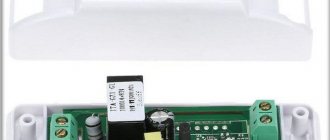
The appearance of the device is ascetic. In the basic version, you have two “Input” contacts for connecting 220V power, and 2 “Output” contacts to which the load is connected; the same 220V appears on them when turned on.
The standard connection diagram is shown below. The wires are connected with screw or clamp terminals, depending on the model.
At the time of writing, you can find Sonoff Wi-Fi relays in blue and orange packages on the domestic market. Blue - ordered mainly from China. Orange packages are products for our market; the words “World On” have been added to the name. Sonoff World On is a kind of localization of the device from ITEAD.
How to add WiFi relay Sonoff
A Wi-Fi device can be paired in two modes: quick pairing and compatible pairing. Before adding a device, make sure your smartphone is connected to a 2.4GHz WiFi network.
1. Press and hold the connect button for 5 seconds until the LED indicator flashes twice.
2. Open the eWeLink app and click the "+" button at the bottom of the screen.
3. Tap Quick Pair.
4. Enter the password for the selected SSID. Click Next.
5. Follow the onscreen instructions to complete pairing.
Note: If your device is running firmware 3.0 or later, your device is in quick pairing mode by default. Skip step 1 and start by opening the eWeLink app.
If you were unable to add a device in quick pairing mode, make sure that you have entered the correct WiFi password.
If pairing fails even with the correct SSID and password, try a compatible pairing mode.
2.Put your device into quick pairing mode. Then press and hold the connect button for 5 seconds. When the LED indicator starts blinking continuously, the device is in compatible pairing mode. Click Next.
Source
Operating principle and setting
All (according to unverified data, almost all) Sonoff Wi-Fi relays are based on the ESP8266 microcontroller, which provides connection to a wireless network. In addition to this, the board contains a power relay, power supply and terminal blocks. There are descriptions, codes and diagrams on the Internet for self-assembly of the device, but the rationality and cost of this idea is questionable.
The operating algorithm is as follows:
The Sonoff Wi-Fi relay connects to your router and communicates with the cloud server. You connect to the Internet from your smartphone and control electrical appliances. You can control the device in “local” mode by pressing a button on its body. And thanks to the simplest connection diagram, home automation does not require deep knowledge of electrical engineering.
Let's figure out how to connect Sonoff to a smartphone, it's not difficult. To connect you need:
- Download the eWeLink application from the Appstore or Play Market.
- Register in it.
- Apply power to the device; in this case, you need to press and hold the button on the relay body (or other connected device from this family) for a long time.
- When the LED indicator starts blinking, release the key.
- Click on the device search icon in the application.
- Specify wireless connection settings.
- Assign a device name and use it from your smartphone or by pressing a button on Sonoff itself.
Wireless control without internet works on RF and Basic models
Everything is quite simple, such work allows you to control devices from anywhere in the world, because communication occurs via the Internet, and not a local network. On thematic forums there is a description of how to untie all Sonoff products from the cloud and make them work over a network without the Internet.
Instructions for setting up Wi-Fi
Smart Wi-Fi sockets controlled via the Internet
Next, more comprehensive instructions will be given for setting up the relay when connecting directly to a smartphone and through a shared router.
Operating mode 1 - the smartphone is connected to the module directly
The first step is to run the USR-TCP232-Test-V1.3 program and run the following commands:
- AT+CWMODE=2 — selection of AP mode;
- AT+RST - restart;
- AT+CIPMUX=1 — installation of multiple connections;
- AT+CIPSERVER=1.8080 — setting up the TCP server and setting the port number;
- AT+CIFSR — view the IP address for the Access Point mode;
- AT+CIOBAUD=9600—sets the port baud rate to 9600 baud.
After this, you need to connect to the access point from your smartphone and download the EasyTCP_20 software for Android from PlayMarket. Launch it and click Connect, entering the device address and port number. After this, commands can be created in blocks that will be sent to the relay.
Operation mode 2 - smartphone and WiFi module are connected to the same router
This also requires running the first utility and running the following commands:
- T+CWMODE=1 — client mode selection;
- AT+RST - restart;
- AT+CWJAP=, — setting up a connection to the router;
- AT+CIPMUX=1 — installation of multiple connections; multiple connections;
- AT+CIPSERVER=1.8080 — setting up the TCP server and setting the port number;
- AT+CIOBAUD=9600—sets the port baud rate to 9600 baud.
Next, you need to connect from your smart phone to the router’s Wifi network and use the same EasyTCP_20 application to start managing the Wi-Fi relay.
Thus, a WiFi relay module is a really useful thing for creating automated home solutions, one of which can even be a “smart home” based on a Wifi relay. It is thanks to their low price and simplicity that these devices have gained their well-deserved popularity.
Podgornov Ilya Vladimirovich All articles on our site are audited by a technical consultant. If you have any questions, you can always ask them on his page.
The lineup
Now that we have figured out how the Sonoff smart relay works, let’s move on to a review of the proposed solutions. By the time this article was written, on the company’s official website there are 9 models of Wi-Fi connectors and 9 models of other smart products: sockets, switches, lamps, sockets. Let's look at what they are and the characteristics of some of them:
- Basic 10A is the simplest model, the relay is designed for current up to 10A, maximum load is 2.2 kW. Operates in the voltage range 90-250V, according to the wireless communication standard 802.11 b/g/n, operating temperature from 0°C to 40°C, Case dimensions: 88*38*23mm.
- RF - distinctive feature: support for remote control via 433MHz radio remote control (not included in the kit, you can bind any one).
- Dual - differs from the characteristics of the previous one only by the presence of two channels. So you can manage two loads from one device, but how many can you connect? The maximum current for one device is 10A and power 2200 W, and for two devices a total of 16A and 3500 W. Case dimensions: 114*52*32mm.
- TH10/TH-16 - models with temperature and humidity sensor: DHT11, AM2301, DS18B20 (temperature only). They connect to the 3.5 mm jack on the side panel. TH10 differs from TH16 in maximum load current - 10 and 16 amperes, respectively.
- POW 16A, the main difference is the ability to monitor the power consumed by the load. This is especially true when used to control a heater with a load current of up to 16A. With the ability to display daily and monthly reports. Case dimensions: 114*52*32mm. In the POWR2 version, it is possible to view the current consumption and what voltage is in the network.
- 4ch PRO is the largest option in the line. The main feature of the characteristics is to control 4 channels of consumers with a power of 2200W, that is, 10A per channel. Size: 145*90*40mm. Designed for installation in an electrical panel on a DIN rail and occupies 8 modules.
The cost of the simplest relay at the time of writing is $3.5, and the most expensive is $20. How many devices can be connected to one Sonoff Wi-Fi relay, as you can see, depends not only on the current consumed, but also on the number of channels
Load management on NodeMCU using a mobile application
We will need:
The nodemcu board itself: https://ali.pub/1qdz7a
nodemcu shield: https://ali.pub/1qdzd4
Relay: https://ali.pub/1qrtft
This article shows an example of using the NodeMCU board. Namely, load control using a relay module of 4 relays and an application for an Android mobile phone.
We connect all contacts according to the diagram
After connecting all the components, you need to copy the program code below and paste it into the Arduino IDE program and load this program code into the Arduino board itself.
#include // Your WiFi network name and password const char* ssid = “test”; const char* password = "test"; // Create a server and port for listening 80 WiFiServer server(80); void setup() { Serial.begin(115200); delay(10); // Prepare GPIO pinMode(5, OUTPUT); digitalWrite(5, 1); pinMode(4, OUTPUT); digitalWrite(4, 1); pinMode(0, OUTPUT); digitalWrite(0, 1); pinMode(2, OUTPUT); digitalWrite(2, 1); // assign a static IP address WiFi.mode(WIFI_STA); // client mode WiFi.config(IPAddress(192,168,1,131),IPAddress(192,168,1,111),IPAddress(255,255,255,0),IPAddress(192,168,1,1)); WiFi.begin(ssid, password); // Waiting for connection while (WiFi.status() != WL_CONNECTED) { delay(500); Serial.print("."); } Serial.println(""); Serial.println("WiFi connected"); // Start the server server.begin(); Serial.println("Server started"); // Print the received IP address Serial.println(WiFi.localIP()); } void loop() { // Check connection WiFiClient client = server.available(); if (!client) { return; } // Waiting for data Serial.println("new client"); while (!client.available()) { delay(1); } // Read the first line of the request String req = client.readStringUntil('\r'); Serial.println(req); client.flush(); // Working with GPIO if (req.indexOf(“/1/0”) != -1) digitalWrite(5, 0); else if (req.indexOf(“/1/1”) != -1) digitalWrite(5, 1); else if (req.indexOf(“/2/0”) != -1) digitalWrite(4, 0); else if (req.indexOf(“/2/1”) != -1) digitalWrite(4, 1); else if (req.indexOf(“/3/0”) != -1) digitalWrite(0, 0); else if (req.indexOf(“/3/1”) != -1) digitalWrite(0, 1); else if (req.indexOf(“/4/0”) != -1) digitalWrite(2, 0); else if (req.indexOf(“/4/1”) != -1) digitalWrite(2, 1); else if (req.indexOf(“/5”) != -1) { Serial.println(“TEST OK”); String s = "HTTP/1.1 200 OK\r\nContent-Type: text/html\r\n\r\n\r\n \r\nTest OK. Uptime: "; // Calculation UpTime int Sec = (millis() / 1000UL) % 60; int Min = ((millis() / 1000UL) / 60UL) % 60; int Hours = ((millis() / 1000UL) / 3600UL) % 24; int Day = ((millis() / 1000UL) / 3600UL / 24UL); s += Day; s += "d "; s += Hours; s += ":"; s += Min; s += ":"; s += Sec; s += "\n"; client.print(s); client.stop(); return; } else // If the request is invalid, write an error { Serial.println("invalid request"); String s = "HTTP/1.1 200 OK\r\nContent-Type: text/html\r\n\r\n\r\n\r\nInvalid request"; s += "\n"; client.print(s); client.stop(); return; } client.flush(); // Formation of the response String s = "HTTP/1.1 200 OK\r\nContent-Type: text/html\r\n\r\n\r\n\r\nGPIO set OK"; s += "\n"; // Send the response to the client client.print(s); delay(1); Serial.println("Client disonnected"); }
Link to the sketch: https://yadi.sk/d/XU-WI08r3M32gF First in this sketch you need to change
// Name and password of your WiFi network const char* ssid = “test”; const char* password = "test";
Then in the line we change the IP address to yours:
WiFi.mode(WIFI_STA); // client mode WiFi.config(IPAddress(192,168,1,131),IPAddress(192,168,1,111),IPAddress(255,255,255,0),IPAddress(192,168,1,1));
Where first is the device’s IP address, 2 is the gateway, 3 is the subnet mask, 4 is the dhcp server address
After uploading the sketch, going to https://192.168.1.131/1/0 and https://192.168.1.131/1/1 we will turn the relay on and off, and therefore by changing 1 to 2,3,4 we will control other relays, for example https://192.168.1.131/3/1
Now let's move on to creating the application:
By following the link: https://ai2.appinventor.mit.edu and logging in, we will be accepted into the program for creating applications for Android.
My application looks like this:
It’s hard to describe here what needs to be added, I’ll try to list what needs to be thrown on the screen.
To control 4 relays we need:
From the left User interface , add 8 Buttons to the screen; for labels above the buttons we need 4 Labels
From the left tab Connectivity Add Web block
To install two buttons in the same plane, we need the HorizontalArrangement block in the left Layout
To fine-tune each added block, you need to select the block that we want to edit on the right in the Components
And in the Properies , all the settings that apply to this object will be revealed.
The general window looks like this:
Blocks tab in the upper right corner
Here we will program using block diagrams.
To begin, in the Blocks , select the first button with which we will work and select the block: when Button1 . Click
Next, in the same Blocks , click on Web and almost at the very bottom select the set Web1 block. Url to
and add it to when Button1 . Click
Next, let’s go to the same Blocks , then Text , and select the very first block that looks like this “ ” and attach it to et Web1. Url to and write in it the address to turn on the relay “ https://192.168.1.131/1/0 ”
Next, in the same Blocks , click on Web and select the purple block call Web1. Get and attach it to when Button1 . Click
This completes the button setup, the same actions need to be done with all the buttons and it should turn out like this:
The application itself can be downloaded from the link: https://yadi.sk/d/BY4kEIYQ3M36LL
The sources can be viewed at this link: https://yadi.sk/d/ehabE3C_3M36Yo This link will download a file with the .aia extension and you can add it to the MIT app invertor and see what the program consists of in full.
Well, who is too lazy to read and is interested in watching the video:
Connection diagrams
We have already talked about the standard connection of a load to a Wi-Fi relay, but it is limited by the switching capacity of the contacts of a small-sized relay. How to connect Sonoff to control a powerful load? If you need to control a powerful load, use a contactor, powerful relay or other switching device.
The Sonoff RF Wi-Fi relay is equipped with a 433 MHz radio module, which means that it can work with radio switches and remote controls. The figure below shows the connection diagram and how to install it instead of a regular light switch for a chandelier.
To install wireless control: remove the old switch, short-circuit its wires (the incoming and outgoing phases to the lamp) and connect Sonoff RF to the lamp's power supply. After that, stick the radio switch anywhere on the wall and use it, but do not forget to bind it. This way you can move the switch to a new location without cutting into the walls.
By the way, the size of the Sonoff Wi-Fi relay allows you to hide it in the bowl of chandeliers and lamp housings.
d application
To control all the above hardware components, we will use a simple Android application. This application will allow us to turn the output on or off directly or after a certain period of time.
Note: The application requires Android 4.0 (IceCreamSandwich) or higher.
- First of all, you must know the IP address of your module. If you used a software serial port, the IP address will be printed in the console. If you used a hardware serial port, then you must use a cable to monitor the data on the RX and TX lines to see the IP address. You also need to know the port number that was specified in the Arduino sketch. After that, click "connect" to get the status of all three outputs. You need to make sure that your Wi-Fi router is turned on and you are connected to the local network.
- Now click on any switch you want to turn on/off. Whenever you want, you can click "refresh" to refresh the status of all outputs.
- In the Timers tab, you can set any of these three outputs to turn on/off after a certain period of time (from 0 to 24 hours).
- After any action, you will receive a confirmation message indicating whether the command completed successfully or some error occurred.
Screenshots of an Android application for controlling a controller on Arduino and ESP8266
Recommendations and features of relays with remote control
Please note that a very short press will not switch the lamp. If the button is held down for less than 0.1 seconds, the receiver does not have time to process the incoming radio signal.
- The wall switch (regular) should always be in the on position. Otherwise, voltage will not flow to either the lamp or the module at all. If you accidentally turn off the light with the wall switch when the module was active (the light was on), then when you turn on the wall switch again, the module automatically switches to the “off” mode. This is protection from a situation when the light in the house suddenly goes out, and you leave forgetting that the lamp was on.
- It will not work to simply connect to the break of one of the network wires (phase or neutral) - both wires must go to the receiver module, so it is placed near the chandelier itself, and not in the wall switch (where there is usually only one mains wire).
- There are different sets on sale: from one to 4 modules, controlled by one key fob or radio switch. They can be easily combined with each other by synchronizing the signal (training).
- Thanks to three contacts, it is possible to use the relay as a pass-through switch.
The radio relay has a wide range of uses in the home, shopping center, electric vehicle, car anti-theft systems, security alarms and other remote control control circuits (garage, curtain, door locks, telemetry, industrial equipment).
The range is sufficient even for a large apartment; there have never been any false alarms in all 5 years of operation of that similar radio relay. In general, the thing is simply gorgeous and in some cases irreplaceable, I definitely recommend it!
Adding and removing a key fob
Adding a key fob: Press the learning button for 3 seconds. The indicator will be off, and then release the buttons, press any button on the remote control to signal, the LED indicator will flash 3 times, which means the remote control is added. This way, if necessary, you can add the required number of key fobs.
Delete all key fobs: press the learning button for about 8 seconds, the indicator will blink that all key fobs have been successfully deleted.