In view of the high cost of electric motors, the issue of protecting them from damage when normal operation is disrupted is quite acute. Among the most popular violations are overload, loss of one of the phases, and reduction in operating voltage. And all of them are characterized by large operating currents flowing in the windings of an electric machine, which leads to overheating, deterioration of the dielectric properties of the insulation and burnout of the cores if the situation is left to chance. To protect electric motors from overheating, a thermal relay is introduced into the power supply circuit of the electric drive.
Design
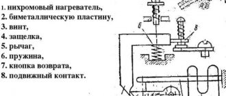
The modern electrical equipment market offers a huge selection of thermal relays of different operating principles; as a result, their design will also differ. However, in accordance with clause 3.2. GOST 16308-84 all technical parameters of a particular model must correspond to this type in terms of dimensions, design and circuit diagram of this type. The most common option, due to its ease of implementation and relative cheapness, is an electrothermal relay on a bimetallic plate. The design of which is shown in Figure 1.
Rice. 1. Thermal relay design
As you can see, the mechanism includes:
- heating element - a current-carrying part that passes through itself the operating current of an electric machine;
- bimetallic plate - acts as an active indicator that reacts to excess temperature;
- pusher - performs the functions of a rigid lever that transmits force from a bimetallic plate;
- temperature compensator – allows you to make a correction for the ambient temperature to stabilize the operating current value;
- latch – designed to fix the position of the temperature relay;
- release rod - a moving part of the mechanism designed to move contacts;
- relay contacts – transmit power to the control unit;
- spring - creates a force to move the relay to a stable position.
In practice, there are other types of relays, the design of which will be fundamentally different. This option is given as an example to illustrate the processes and explain the operating principle.
Connection, adjustment and marking
The overload switching device, unlike an electrical circuit breaker, does not break the power circuit directly, but only sends a signal to temporarily shut down the facility in emergency mode. Its normally switched contact works as a contactor “stop” button and is connected in a series circuit.
Device connection diagram
In the relay design, there is no need to repeat absolutely all the functions of the power contacts upon successful operation, since it is connected directly to the MP. This design allows for significant savings in materials for power contacts. It is much easier to connect a small current in the control circuit than to immediately disconnect three phases with a large one.
In many schemes for connecting a thermal relay to an object, a permanently closed contact is used. It is connected in series with the “stop” button of the control panel and is designated NC - normally closed, or NC - normal connected.
An open contact with such a scheme can be used to initiate the operation of thermal protection. Connection diagrams for electric motors in which a thermal protection relay is connected may vary significantly depending on the presence of additional devices or technical features.
In a standard simple circuit, the TP is connected to the output of a low-voltage starter on an electric motor. Additional contacts of the device must be connected in series with the starter coil
This will provide reliable protection against electrical equipment overloads. In case of unacceptable excess of current limit values, the relay element will open the circuit, instantly disconnecting the MP and the engine from the power supply.
The connection and installation of a thermal relay, as a rule, is carried out together with a magnetic starter designed for switching and starting an electric drive. However, there are types that are mounted on a DIN rail or a special panel.
Subtleties of adjusting relay elements
One of the main requirements for electric motor protection devices is the precise operation of the devices in the event of emergency operation of the motor. It is very important to select it correctly and adjust the settings, since false positives are absolutely unacceptable.
An electrothermal relay, which is optimally suited to a specific type of engine in all technical parameters, is capable of providing reliable protection against overloads in each phase, preventing a prolonged start of the installation, and preventing emergency situations with jamming of the rotor
Among the advantages of using current protection elements, one should also note a fairly high speed and a wide response range, and ease of installation. To ensure timely shutdown of the electric motor during overload, the thermal protection relay must be configured on a special platform/stand.
In this case, inaccuracy due to the natural uneven spread of rated currents in the NE is eliminated. To test the protective device on a bench, the fictitious load method is used.
A reduced voltage electric current is passed through the thermocouple to simulate the actual thermal load. After this, the exact time of operation is accurately determined using the timer.
When setting up basic parameters, you should strive for the following indicators:
- at 1.5 times the current, the device should turn off the engine after 150 s;
- at 5...6 times the current it should turn off the motor after 10 s.
If the response time is not correct, the relay element must be adjusted using the control screw.
For correct operation, it is necessary to set the device to the highest permissible electric current of the motor and air temperature
This is done in cases where the rated current values of the NE and the motor differ, as well as if the ambient temperature is below the nominal one (+40 ºC) by more than 10 degrees Celsius.
The operating current of the electrothermal switch decreases with increasing temperature around the object in question, since the heating of the bimetallic strip depends on this parameter. If there are significant differences, it is necessary to further adjust the thermocouple or select a more suitable thermoelement.
Sharp temperature fluctuations greatly affect the performance of the current relay. Therefore, it is very important to choose a NE that can effectively perform basic functions, taking into account real values.
It is recommended to place the TR in the same room as the protected electrical installation. They should not be installed close to heat generators, heating furnaces and other heat sources.
These restrictions do not apply to temperature compensated relays. The current setting of the protective device can be adjusted in the range of 0.75-1.25x from the rated current of the thermoelement. The setup is done in stages.
First of all, the correction E1 is calculated without temperature compensation:
E1=(Inom-Ine)/c×Ine,
Where
- In – rated motor load current,
- Ine – rated current of the working heating element in the relay,
- c is the price of the scale division, that is, the eccentric (c=0.055 for protected starters, c=0.05 for open ones).
The next step is to determine the E2 correction for ambient temperature:
E2=(ta-30)/10,
Where ta (ambient temperature) is the ambient temperature in degrees Celsius.
The last stage is finding the total correction:
E=E1+E2.
The total correction E can be with a “+” or “-” sign. If the result is a fractional value, it must be rounded down to a whole number downwards/larger in magnitude, depending on the nature of the current load.
To adjust the relay, the eccentric is transferred to the resulting value of the total correction. A high response temperature reduces the dependence of the operation of the protective device on external indicators.
The thermal protection relay allows manual smooth adjustment of the device's operating current within ±25% of the rated current of the electromechanical installation
The adjustment of these indicators is carried out by a special lever, the movement of which changes the initial bend of the bimetallic plate. The operation current can be adjusted over a wider range by replacing the thermoelements.
Modern overload protection switching devices have a test button that allows you to check the serviceability of the device without a special stand. There is also a key to reset all settings. They can be reset automatically or manually. In addition, the product is equipped with an indicator of the current state of the electrical appliance.
Marking of electrothermal relays
Protective devices are selected depending on the power of the electric motor. The main part of the key characteristics is hidden in the symbol.
This is what the marking of thermal relays from the KEAZ plant looks like. When choosing, it is important to pay attention to the rated current of the model in question so that it is sufficient
You should focus on certain points:
- The range of setting current values (indicated in parentheses) varies minimally among different manufacturers.
- The letter designations for a specific type of execution may vary.
- Climatic performance is often presented in the form of a range. For example, UHL3O4 should be read as follows: UHL3-O4.
Today you can buy a variety of device variations: relays for alternating and direct current, monostable and bistable, devices with deceleration when turned on/off, thermal protection relays with accelerating elements, thermal protection relays without a holding winding, with one winding or several.
These parameters are not always displayed in the labeling of devices, but must be indicated in the data sheet of electrical products.
The following article will introduce you to the structure, types and markings of an electromagnetic relay, which we recommend that you read.
Principle of operation
The work is based on the principle of the difference in temperature expansion of different metals, described by the Joule-Lenz law. When a bimetallic plate consisting of two metals with different coefficients of thermal expansion is heated, its geometric deformation will occur. It is this plate that is installed in the thermostat; it reacts when the temperature exceeds the established limit.
To consider the principle of operation of a temperature relay, we will use a three-dimensional model of a real device shown in Figure 2 below:
Rice. 2. Operating principle of the temperature relay
As you can see, a thermal relay connected to the electric motor circuit passes the main load of the electric machine through the current-carrying buses. If we simulate an overload situation, when a current several times higher than the rated current flows through them, the busbars will begin to heat up and the excess heat will transfer to the bimetallic plate connected to each of the phases of the electric motor. When the set temperature is reached, the bimetallic plate will bend and move one of the pushers. The pusher, in turn, will move the latch lever a few millimeters, which will release the spring mechanism and allow the release rod to move.
After this, the contacts of the thermal relay will turn off the power to the control circuit and close the contacts of the alarm circuit, which will notify that the protective device has been disconnected. After eliminating the cause of overheating, the relay returns to its operating position by pressing a mechanical button. It should be noted that immediately after turning off the thermal relay, it will not be possible to turn it on, since the bimetallic plate has not yet cooled down and false alarms are possible. Therefore, the process requires a certain time delay, after which the electric motor can be put into operation.
Smart search
The choice of a thermal relay must follow the rules. The operating current rating is taken as the basis. Moreover, the standards, both domestic and international, imply that the minimum will be similar to that established for the protection to operate.
This provides for activation of the device only when the line is overloaded by 20-30%. But no later than 20 minutes. That is, in order to avoid false switching on, the starting parameters must be 12% higher than the nominal ones.
Overheat protection Source prom.st
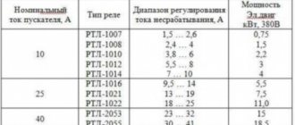
And if there is an asynchronous motor with a power of 1.5 kW, connected to a 380 V network, then a relay with a threshold current of 3.36 Amperes is suitable for it. Because the operating rating of such a motor is 2.8 A. And if you look at the tables in special reference books, then the RTL-1008 thermal relay operates in the range from 2.4 to 4.0 Amperes.
If the motor data is unknown, it is necessary to measure the current at each phase of the line. To do this, use either a current clamp or a multimeter. It is important to pay attention to the voltage at which the relay operates. And installation into a network with three phases must be done through an additional module that protects against phase imbalance.
Designation on the diagram
When reading diagrams, it is important to be aware of the designation of all devices depicted on them. This makes it possible to ensure precise connection in compliance with the basic operating parameters of the electrical installation, selectivity of protection operation and maintain normal power supply mode. The image of a thermal relay in the diagrams is determined by the provisions of two regulatory documents. In accordance with Table 3 of GOST 2.755-87, the contacts of this type of equipment are shown as follows (Figure 3):
Rice. 3. Image of thermal relay contact
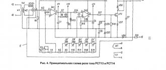
At the same time, the temperature relay itself has a designation in accordance with clause 21 of Table 1 of GOST 2.756-76 , which is displayed on the diagram as follows (see Figure 4):
Rice. 4. Sensing part of the electrothermal relay
Knowledge of schematic images of an electrothermal relay will allow you to navigate the circuit diagrams of already operating units. Or independently compose and connect the equipment through a protective device.
Designation TP for motor with PTC
Motor protection TP 211 is only realized when PTC thermistors are fully installed at the ends of the windings at the factory. Protection TP 111 is only realized when installed independently on site. The motor must be tested and certified to comply with the TP 211 marking. If a motor with PTC thermistors has TP 111 protection, it must be equipped with an overload relay to prevent the effects of stalling.
Compound
The figures on the right show connection diagrams for a three-phase electric motor equipped with PTC thermistors with Siemens releases. To implement protection against both gradual and rapid overload, we recommend the following connection options for electric motors equipped with PTC sensors with protection TP 211 and TP 111. Electric motors with protection TP 111
If a motor with a thermistor is marked TP 111, this means that the motor is only protected against gradual overload. In order to protect the electric motor from rapid overload, the electric motor must be equipped with an overload relay. The overload relay must be connected in series with the PTC relay.
Kinds
The modern variety of thermal relays covers a fairly wide range. Therefore, division into types is carried out in accordance with established criteria based on clause 1.1. GOST 16308-84 . Thus, according to the type of operating circuit current, all devices are divided into two large groups: AC and DC relays. Depending on the number of working poles there are:
- single-pole – used for DC motors and other single-phase models;
- two-pole - installed in a three-phase circuit, where control can be carried out only in two phases;
- three-pole - relevant for powerful asynchronous units with a squirrel-cage rotor.
Depending on the type of contacts of the secondary circuits, all thermal appliances are divided into models:
- only with normally open contact;
- only with normally open contact;
- with both make and break contacts;
- with switching;
Depending on the method of returning the thermal relay to its original position, there are options with manual activation or with self-return. The models can also implement the function of transferring from one type of work to another.
There is also a division based on the presence or absence of a device to compensate for the temperature of the surrounding space. And models with the ability to adjust the non-operation current or without such a function.
Model overview
The table provides a brief comparative overview of thermal relay models, indicating the main parameters and approximate cost.
| Model name | Characteristics | Approximate price, rub. |
| RTL 10A | Alternating current up to 660V and frequency 50Hz or 60Hz Direct current up to 440V | 320 |
| RTE-1304 | Rated current 0.4-0.63 A Current frequency 50 Hz Voltage 660 V | 340 |
| RTT5-10-1 | Overload relay Type of current: alternating Setting range 5.00 A | 490 |
| TRN10 | Switched current: alternating - 3 A at 380 V; 1 A at 660V | 270 |
| RTK | Voltage: 220 V current - 1.3 A | 440 |
Thermal overload relay RTL-1010M with dust and moisture protection level IP20
Purpose
The main purpose of a thermal relay is to protect the electric motor from phase imbalance, overheating during long starts, shaft jamming or excessive load. To solve all these problems, in practice, various types of relays are produced that have a narrow specialization in a specific area; we will consider each of them in more detail below.
- RTL is used to protect three-phase asynchronous electrical machines from the effects of overload currents, overheating due to phase failure or imbalance, and problems with shaft rotation. Can be used either independently or with installation on a PML starter.
- The RTT is designed to work with three-phase units with a squirrel-cage rotor and provides full coverage of emergency modes that lead to overheating of the windings. It can also be installed on a magnetic starter PMA, PME or independently on a mounting panel.
- RTI is a three-phase thermal relay with the possibility of mounting on starters of the KMT, KMI series. They are characterized by stable low power consumption and are switched on together with fuses.
- TRN – used to control the start-up and operating mode of an electric motor; it is little dependent on external temperature factors. It is a two-pole model that can be used to start DC motors.
- Solid-state - unlike the previous ones, it does not have contact groups and moving elements inside. It is used in three-phase circuits where increased fire safety requirements are established.
- RTK - controls temperature indicators not through operating currents, but by placing a sensor in the motor housing. Therefore, the entire interaction process is carried out only by temperature.
- RTE is a kind of fuse, since the shutdown occurs due to the melting of the conductor. The thermal device itself is mounted directly with the electric motor.
How does thermal protection work?
The operating principle of a thermal relay is related to the ability of metals to expand when heated. Two plates made of different metals are mounted in the device. But their coefficients of thermal expansion are different. The elements are rigidly connected to each other.
When the system is overloaded, an increase in current strength is required to continue operation. The process is accompanied by intense heat release. The contact plates heat up and become bent towards the area with a lower temperature coefficient.
Moreover, everything proceeds sequentially. Difficulties in motor operation increase the current strength. The stronger the latter, the faster the heating takes place. A plate brought to the emergency incandescence limit will bend and open the contract in a section of the circuit.
The structure of a thermal relay Source oboiman.ru
When installing thermal relays to protect electric motors, the climatic conditions in the building should be taken into account. If it is very hot in the area where the motor is operating, then when setting the relay it is necessary to set the maximum parameters with a margin. To compensate for temperature differences.
Since the contact material becomes very hot before operation, it must be given time to cool down. Otherwise, the device will turn off the system again after a short time. But, as a rule, during the time the problems are corrected, the bimetallic plates manage to return to normal.
The thermal relay consists of:
- heating element;
- bimetal plates;
- pusher;
- temperature compensator;
- latches;
- release rods;
- contact group;
- springs.
Let's figure out how thermal protection of an electric motor occurs. Current constantly passes through the heating element. If the temperature of the latter increases, then the system has begun to work under load. When a given overload parameter is reached, the bimetallic plate becomes deformed.
Deformation of a bimetallic plate Source meteo59.ru
It moves the pusher, which activates the temperature compensator. The latter moves the latch to the side so that the release rod can rise up and open the contact group. And to return everything to its original position, you need a spring, which is activated by a special button.
Specifications
Correct operation of relay protection is ensured by matching the parameters of the thermal device to the specified operating conditions of the electrical machine. Therefore, it is important to study the basic operating parameters of the relay before purchasing it. The main technical data of the thermal relay include:
- the rated voltage value and frequency for which it is designed;
- time-current characteristic – determines the response time at a set excess factor;
- time for the thermal element to return to its original position;
- setting current change range;
- thermal resistance to exceeding the operating value;
- climatic design and degree of dust and moisture protection.
Marking of thermal relays
The labeling indicates most of the important characteristics of the TR. Example designation: RTL-Х1Х2Х3-Х4-Х5А-Х6А-Х7Х8, where
- RTL – type of thermal relay;
- X1 – rated current, 1 – up to 25 A, 2 – up to 100 A, 3 – up to 250 A, 4 – up to 510 A;
- X2 – 3 digits (conventionally), indicating the range of the current setting;
- X3 – letter characterizing the performance;
- X4 – return method: 1 – manual, 2 – self-return;
- X5 – Inom, A;
- X6 – current setting range, A;
- X7 – climatic version;
- X8 is a trademark.
A thermal relay is an effective element of protection for electric motors and other electrical equipment, which compares favorably with the input circuit breaker in that it is not subject to false alarms during short-term current surges.
Connection diagrams
The connection of the above models of thermal relays can be made according to several schemes, differing depending on the specific type of equipment. Let's consider the most relevant of them.
Rice. 5. Thermal relay connection diagram
As you can see in Figure 5, three-phase relay RT1 is connected in series to motor M. Power is supplied to them through contactor KM. In normal operation, the RT1 contacts are normally closed and current flows through the KM coil. As soon as an emergency mode occurs, the thermal protection will open the contacts and the contactor coil will be de-energized, powering the motor will be cut off.
A two-pole relay is switched on in a similar way, with the difference that the contacts of the protective device are connected in series only in two phases out of three, as shown in the figure below:
Rice. 6. Connection diagram for a two-pole relay
In addition, there is a circuit for switching on a thermal relay for powerful electric motors, the operating current of which is several times higher than the permissible limit for the protective device. In such situations, transformer conversion is used, and the connection diagram looks like this:
Rice. 7. Transformer connection diagram
Why are protective devices needed?
Even if the electric drive is properly designed and used without violating the basic operating rules, there is always the possibility of malfunctions.
Emergency operating modes include single-phase and multi-phase short circuits, thermal overloads of electrical equipment, jamming of the rotor and destruction of the bearing unit, phase loss.
When operating under high loads, an electric motor consumes a huge amount of electricity. And when the rated voltage is regularly exceeded, the equipment heats up intensely.
As a result, the insulation quickly wears out, which leads to a significant reduction in the service life of electromechanical installations. To eliminate such situations, a thermal protection relay is connected to the electric current circuit. Their main function is to ensure normal operation of consumers.
They turn off the motor with a certain time delay, and in some cases instantly, to prevent destruction of insulation or damage to individual parts of the electrical installation.
The current relay constantly protects the electric motor from phase failure and technological overloads, as well as rotor braking. These are the main reasons why emergency situations occur
In order to prevent a decrease in insulation resistance, protective shutdown devices are used, but if the task is to prevent cooling failure, special devices with built-in thermal protection are connected.
Criterias of choice
The main criterion when choosing a specific model is that the rated load corresponds to the permissible range of the thermal relay itself. For normal operation of an electric machine, you need to operate at a 20 - 30% overload in no more than a 5 minute interval. The current value is calculated by the formula:
Iwork = 1.2*Inom
This means that the permissible control limit must include the resulting tripping current value. Then, check on the time-current characteristic (see Figure 8) for what period of time the protection will operate at this multiplicity:
Rice. 8. Time-current characteristic
In this case, the time will be equal to 4 minutes at 20% thermal excess, which fully satisfies the criteria of the task.
Basic characteristics of a current relay
The main characteristic of a thermal protection switch is the pronounced dependence of the response time on the current flowing through it - the greater the value, the faster it will operate. This indicates a certain inertia of the relay element.
The directed movement of charge carrier particles through any electrical appliance, circulation pump and electric boiler, generates heat. At rated current, its permissible duration tends to infinity.
And at values exceeding the nominal values, the temperature in the equipment increases, which leads to premature wear of the insulation.
A broken circuit instantly blocks further temperature increases. This makes it possible to prevent engine overheating and prevent emergency failure of the electrical installation.
The rated load of the motor itself is a key factor determining the choice of device. An indicator in the range of 1.2-1.3 indicates successful operation with a current overload of 30% over a time period of 1200 seconds.
The duration of the overload can negatively affect the condition of electrical equipment - with a short-term exposure of 5-10 minutes, only the motor winding, which has a small mass, heats up. And if it lasts for a long time, the entire engine heats up, which can lead to serious damage. Or it may even be necessary to replace burned-out equipment with new ones.
In order to protect the object as much as possible from overload, you should use a thermal protection relay specifically for it, the response time of which will correspond to the maximum permissible overload ratings of a particular electric motor.
In practice, it is impractical to assemble a voltage control relay for each type of motor. One relay element is used to protect motors of various designs. At the same time, it is impossible to guarantee reliable protection over the full operating interval limited by the minimum and maximum load.
An increase in current indicators does not immediately lead to a dangerous emergency condition of the equipment. It will take some time before the rotor and stator reach their maximum temperature.
Therefore, it is not absolutely necessary for the protective device to react to every, even slight, increase in current. The relay should turn off the electric motor only in cases where there is a danger of rapid wear of the insulating layer.