Switching processes are basic in all automated control systems. The most common switching elements in this case are intermediate electromagnetic relays.
Despite the large number of different semiconductor devices, electromagnetic relays are still used in all kinds of industrial equipment and household appliances. The popularity of relays is due to their reliability and high performance characteristics, which directly depend on the characteristics of the metal contacts.
What are relays and where are they used?
An electromagnetic relay is a high-precision and reliable switching device, the operating principle of which is based on the influence of an electromagnetic field. It has a simple design, represented by the following elements:
- coil;
- anchor;
- fixed contacts.
The electromagnetic coil is fixed motionless on the base, there is a ferromagnetic core inside it, a spring-loaded armature is attached to the yoke to return to its normal position when the relay is de-energized.
Simply put, a relay opens and closes an electrical circuit in accordance with incoming commands.
Electromagnetic relays are reliable in operation, which is why they are used in various industrial and household electrical appliances and equipment.
What is a relay: a brief excursion into history
The term comes from the English language, from the word “reley,” which in the old days meant the change of post horses, and later the passing of the baton in sports competitions. There are two versions of creating such a device. According to the first relay, the Russian scientist P.L. invented it. Shilling in the early 30s of the last century. This was the main component in the telegraph he developed. However, most historians are inclined to believe that the progenitor of the relay was the American George Henry. A non-switching device based on the electromagnetic principle of operation became widespread in 1937. It was then that the first telegraph went into production.
It is now impossible to say which of these versions is correct. Perhaps, as often happens, scientists developed the device in parallel, unaware of each other's inventions. This is also evidenced by the fact that historians call the same period of time for the appearance of the relay - 1931-1935.
This device turns off the voltage when the network is overloaded with power, saving electrical wiring
Types of devices
All existing magnetic relays are divided into several varieties depending on their design features, scope of application, control signal power, type of electric current, control speed.
According to the characteristics of the relay device, they can be:
- Contact. They act on the circuit with several contacts. Their closing or opening helps ensure commutation - the power circuit is either connected or broken.
- Contactless. They affect the circuit differently. These
- devices dramatically change its characteristics.
According to the scope of use, there are signaling, protective and intended for control circuits.
Electromagnetic relay
Based on the speed of action, switching devices are divided into four types:
- Adjustable. When using them, you can set any speed.
- Slowed down. They operate no earlier than after 0.05 s.
- Fast-acting. Such relays begin to operate within a millisecond.
- Inertia-free. This type of device is active even before one millisecond has elapsed.
Depending on the power of the control signal, the relay can belong to one of three main types. Power can be:
- high if its value exceeds 10 W;
- average at a value of up to 10 W, but not less than 1 V;
- small, the value of which is measured in fractions of a watt.
The relay can be used in AC or DC networks. The latter are polarized and neutral.
HOW RELAY WORKS [RadioamatelTV 75]
Main types of EMR
EMR relays are usually classified according to several parameters. Based on the design features, contact and non-contact devices are divided. In the first case, we are talking about devices that, when triggered, act with a contact group on the power circuit, providing a connection or break in it. In the second, a similar result is achieved by changing one of the parameters (voltage, current, capacitance, resistance).
Depending on the method of connection, equipment is divided into the following types.
- Primary (the device is connected directly to the control circuit).
- Secondary, requiring connection to the network through a measuring current transformer.
- Intermediate, operating from the executive bodies of other relay devices. This principle of operation allows for signal multiplication or amplification.
Depending on the type of input voltage, DC and AC devices are produced. The first option, in turn, can be divided into polarized and neutral. Its key difference is the sensitivity of the device to the polarity of the power source (depending on this, the armature changes the direction of movement of the armature).
Among the disadvantages of DC equipment are the relatively high cost and the need for use in conjunction with a power supply. Such problems do not arise when operating an AC EMR, but their significant “minus” will be vibration during operation and reduced sensitivity.
Current relay
The current relay is designed to monitor this parameter in electrical consumer circuits. It is possible to connect the device to power circuits or using an instrument transformer. Data transfer to other circuits is carried out by connecting a resistor.
The main design difference of a current relay is the design of the coil. It uses a thick conductor, which has low resistance and is wound on the core with a small number of turns. To control the specified parameters, an automated on/off system is provided.
Time relay
In most cases, time relays are installed when it is necessary to form start-up cascades when connecting high-power equipment. This approach allows you to avoid sudden load surges when the equipment is turned on, exceeding the permissible values. The time delay is provided by an additional short-circuited circuit, the role of which is played by a copper sleeve placed on the core.
The operating principle of a time relay is based on the “quenching” of the electromagnetic field strength due to the presence of oppositely directed current. As a result, a delay is formed, the value of which can be 0.07–0.15 s. The adjustment is performed by the EMR armature spring. The same effect is observed when turning off the power, but the delay may be 0.5–2 s.
Main characteristics
The magnetic device has many characteristics. Its most important parameters are the following:
- Speed of action. This is the time it takes for the device to operate after a signal is given.
- Trigger power. The minimum required to start the action.
- Controllable power. This power can be controlled by switching contacts.
- The magnitude of the operating current. This parameter is called the setpoint.
- Release current. This is the highest current value at which the sensitive plate begins to return to its starting point.
The advantage is that magnetic relay contacts have low resistance, unlike semiconductor-based switches. Another important advantage is that its metal contacts can withstand heavy network overloads. In addition, the relay can normally perform its basic functions even in the presence of static electricity. Radiation does not affect its operation.
The main advantage of the electromagnetic device is the galvanic isolation of the control and switching electrical network without secondary elements. To all of the above, it is worth adding a low price.
It also has some disadvantages. Firstly, it doesn't work very quickly. Secondly, it often fails. Thirdly, interference may occur when switching the circuit.
EVERYTHING you wanted to know about RELAYS. Types and methods of connection - in Theory and in Practice!
Main structural components and operating principle of contact relays
In the future, the optimal combination of contact and non-contact devices should be considered the most acceptable. The use of certain devices in specific automation and telemechanics systems is determined on the basis of operational, technical and economic requirements for newly developed and designed systems.
The considered classification and main characteristics apply only to contact relays.
Requirements for relay operation reliability
Based on reliability, relay actions are divided into I and lower reliability classes.
Relays of class I reliability include relays in which the return of the armature when the current in the windings is turned off is provided with the maximum guarantee and is carried out under the influence of its own weight (gravity). Relays of reliability class I also have the following additional properties that ensure high reliability of their operation:
non-weldability of front contacts that close the most critical circuits when the relay is energized; for this purpose, the front contacts are made of graphite with an admixture of silver, and the remaining contacts are made of silver;
reliable contact pressure and relatively large intercontact distances (pressure on the front contacts is at least 0.3 N, on the rear contacts - at least 0.15 N), the gap between the contacts at the extreme positions of the armature must be at least 1.3 mm; preventing the armature from sticking when the current in the relay winding is turned off, which is ensured by the presence of antimagnetic pins on the armature.
Relays of class I reliability are used in all automation and telemechanics systems without additional circuit control for armature release.
For relays of lower reliability classes, the return of the armature when the current in the relay windings is turned off can be ensured both under the influence of its own weight and under the action of the reaction forces of the contact springs. These relays, as a rule, are used in schemes not directly related to ensuring the safety of train traffic (dispatcher control, route-relay centralization dialing circuits, code equipment for dispatch centralization, etc.). When using these relays in critical circuits (automatic blocking and ALS decoders, track relays of pulsed rail circuits, etc.), mandatory circuit control is provided for the attraction and release of the relay armature during continuous pulse operation. If these relays operate in critical circuits with continuous power supply, then their duplication is used (parallel or serial connection of relay windings and sequential connection of contacts).
Magnetic relay system
In the design of the relay, magnetic materials should be used that have maximum magnetic permeability and low coercive force and are not subject to noticeable aging.
Ferromagnetic material exhibits the phenomena of hysteresis and saturation and whose permeability depends on the strength of the magnetic field. Microscopically, elementary magnets line up parallel in volumes called domains. The non-magnetized state of a ferromagnetic material is due to the complete neutralization of domain magnetization, creating zero external magnetization.
The relay design should provide for maximum use of magnetic material for its primary purpose. The traction force of the relay electromagnet and the opposing mechanical forces that arise during the movement of the armature must be coordinated so that strong impacts of the armature on the core are excluded and the correspondence of the position of the contacts with the position of the armature is not disrupted. The movement of the armature is limited by stops, which must be made of a completely anti-magnetic and corrosion-resistant material.
During the prescribed service life of the relay, the air gap for the attracted armature should not be less than 0.2 mm, so as not to cause the armature to stick.
A magnetic circuit is a device containing cores made of ferromagnetic materials through which a magnetic flux is closed.
Fig.1.7
Fig.1.7
Magnetic circuits are components of electrical installations: motors, generators, transformers, relays and other devices.
The magnetic circuit is a combination of a source of magnetizing force and a magnetic circuit.
The source of the magnetizing force is usually a winding (coil) with current or a permanent magnet.
Magnetic cores are designed to enhance the magnetic flux and give the magnetic field a certain configuration. Sometimes the magnetic circuit may include air gaps. Ferromagnetic materials are used as materials for magnetic circuits.
Ohm's law for an unbranched magnetic circuit: magnetic flux is directly proportional to the magnetomotive force and inversely proportional to the total magnetic resistance of the circuit.
(practically not used due to nonlinearity of resistances).
Kirchhoff's laws for magnetic circuits:
I Kirchhoff's law for a magnetic circuit
–
the algebraic sum of magnetic fluxes in a node of a magnetic circuit is equal to zero.
Kirchhoff's II law for a magnetic circuit
–
in the contour of a magnetic circuit, the algebraic sum of magnetomotive forces is equal to the algebraic sum of magnetic stresses in individual sections.
To calculate a magnetic circuit means, based on a given magnetic flux (magnetic induction), magnetization curves and geometric dimensions of the magnetic circuit, determine the magnetizing force necessary to create a given flux.
Calculation of unbranched magnetic circuits:
1. Draw an average magnetic line and along it divide the circuit into homogeneous sections (i.e., the same cross-section and magnetic permeability) and determine their length and cross-section.
2.According to the formula V=F/S
determine the magnetic induction of areas.
3. The required tension for areas made of ferromagnetic materials is found from the magnetization curves, and for air gaps using the formula H0 = V/m0.
4. According to the law of total current, adding the magnetic voltages of all sections determines the magnetizing force necessary to create a flux Ф in a given circuit: Iw=Н1l1+H2l2+…
Fig.1.8
The simplest electromagnet is a steel core on which a coil is placed.
Fig.1.8
Relay contact system
Influence of physical factors on contact resistance. Contact system parameters.
1. Contact solution - the shortest distance between the open contact surfaces of the moving and fixed contact parts.
2. Failure of the contact system - promotion of moving contact
after contact of contact surfaces ( l
).
3. Contact pressure – force that compresses contacts. pH varies
and the final
Pk
of pressing, where
Pk
=
Pn
+
c l
(
c
is the stiffness of the contact spring).
Contact Press:
By increasing the contact pressure, the contact resistance decreases. This is explained by the fact that as the pressure on the contacts increases, the actual area of their contact increases due to the deformation of irregularities on the contacting surfaces. With a further increase in pressure, the contact material is deformed to a lesser extent, and the decrease in contact resistance slows down
The nature of the change in contact resistance with a decrease in contact pressure is different. This is due to the presence of residual deformation of microroughnesses on the contacting surfaces. This is true for solid metal contacts.
For FMC, the contact resistance is practically independent of pressure and is several times lower than for solid metal contacts. This is explained by the fact that in FMC the actual contact surface is equal to the apparent one, i.e., microroughness of the contact surface does not affect the value of the contact resistance.
Contact surface:
By increasing the contact surface area, the number of points of contact n
in expression.
However, for solid metal contacts, the influence of the contact surface on the transient contact resistance is small due to the fact that the transient resistance depends not on the specific, but on the full pressure on the contacts, since contacting occurs not over the apparent contact area, but at the contact point (actual area).
However, the size of the contact surface must be taken into account due to the fact that when current flows through the contact, heating of the contact material occurs. Therefore, at high currents, electrical losses can be significant and a sufficient surface area of the contact connection is required to remove heat from the contact.
The resistance of FMCs decreases significantly with increasing area of their contact, due to the reason indicated above.
Temperature of the contact surface.
With an increase in the heating temperature of a solid metal contact, its contact resistance increases due to an increase in the electrical resistivity of the contact material
But with increasing temperature, the contact surface increases, since the deformation of microroughnesses on the contacting surfaces increases due to a decrease in the mechanical strength of the contact material, and the contact resistance decreases. A subsequent sharp decrease in the transition resistance (at point d) after some increase occurs when the melting temperature of the contact material is reached.
The resistance of the liquid metal monotonically increases with increasing temperature (straight line 2), due to an increase in the specific resistance of the liquid metal.
When current passes through the contact surface, heat is released. Due to the presence of transition resistance, the temperature of the contact surface exceeds the temperature of the contact part. The temperature of the contact pad above the temperature of the contact part will correspond.
The Peltier effect occurs when current flows through the contact point of conductors made of 2 dissimilar metals. It is explained by the presence of a contact potential difference. If the electric field created by the contact potential difference accelerates electrons, then Peltier heat is released at the junction; If the field retards the movement of electrons, then heat is absorbed.
The Kohler effect is the result of tunneling resistance inherent in films on the surface of contacts in contact. The kinetic energy of tunnel electrons passing through the film increases when they reach the anode, which has a lower negative potential than the cathode. Excess energy is converted into heat. As a result, the anode side of the film heats up more.
All three effects take place regardless of the release of Joule heat in the contact. They can acquire a significant influence only in contacts when very small currents flow.
Condition of contact surfaces.
It was noted above that the value of contact resistance is significantly affected by oxide films and contamination on the contact surfaces. This especially affects contacts operating in chemically aggressive environments, in conditions of elevated temperature, humidity, and dust. Except for some noble metals (gold, platinum), almost all metals interact with the environment, forming various films.
It should be noted that silver oxides have low electrical resistance comparable to that of pure silver. Therefore, given the relatively low cost of silver, silver contacts are most widely used in electrical devices.
Corrosion of contact surfaces can lead to temporary or complete disruption of contact conductivity.
Strong oxidation of copper begins already at 70°C, and at 100°C the resistance of copper contacts can increase several tens of times. Contacts must be protected from corrosion. This is done by using anti-corrosion coatings made of metal, varnish or lubricant. To protect contacts from corrosion, great force is applied to the contact surfaces (mechanical destruction of oxide films occurs).
In commutating movable contacts, the effect of self-cleaning of contact surfaces from oxide films occurs due to their destruction during friction and mutual movement of the contacts relative to each other.
Grinding contact surfaces increases the contact resistance compared to filing, since when grinding, the tubercles and micro-irregularities on the contact surface become more
flat, and crumpling them is difficult.
Operating time
The electrical resistance of the contact does not remain constant over time, since the thickness of the oxide films on the contact surface increases over time. However, this increases the voltage drop across the contact junction, the electric field gradient in the film, and the contact temperature
The combined effect of high heating temperature and electric field leads to electrical breakdown (fritting) and destruction of the oxide film. The contact resistance drops, but subsequently the process repeats.
Features of the operation of movable contact connections
Contact operating modes
— the operation of the moving contacts of the devices is divided into three modes: closed state, opening of contacts, closing of contacts.
Closed state.
The processes occurring in the closed state of contact connections are similar to the processes occurring in stationary contacts. This is the most favorable moment of operation for moving contacts.
The process of opening the circuit.
This is the most difficult moment in the operation of moving contacts. The opening process has several phases.
a) Initial phase - from t
= 0 to
t
=
T
1, the contacts have not yet diverged, but either the area or the force on the contacts changes, which leads to a change in the transition resistance
G
per.
At t
=
T
1
Г
the perm increases sharply,
causing increased heating of the contact, which may be sufficient to melt the contact material.
b) Phase at t
≥
T
1 corresponds to the beginning of contact divergence.
In this case, at first there will be a liquid bridge of molten metal between the contacts, which, with further divergence of the contact, is interrupted, carrying away part of the metal from the anode. c) During this phase of contact divergence, a sharp increase in the voltage drop across the contacts occurs, which can lead to the occurrence of a gas discharge (arc). For example: for Cu
:
U
= 12 V,
I
= 0.42 A;
for Al
:
U
= 14 V,
I
= 0.5 A.
The process of closing a circuit.
When the distance between the contacts decreases to 10−5 cm, the voltage gradient E
=
dudx
.
Under the influence of this electric field E,
field emission of electrons occurs from the cathode surface, which causes a spark to appear. Since in
the next moment in time the contacts close, then the spark usually does not have time to turn into an arc. However, an arc may occur when the contacts close if they vibrate. Thus, the occurrence of electrical discharges when closing and opening moving contacts leads to their destruction due to electrical wear
.
Electrical contact wear. Electrical wear or erosion
– these are physical phenomena (melting, evaporation, metal sputtering) that occur in workers
surfaces. Accompanied by the transfer of metal from one contact to another. At low currents, contact destruction is caused by melting of contact points and pulling out of liquid metal bridges. The consequence of this is the transfer of the contact metal from the anode to the cathode and the formation of a needle on the surface of the cathode and a depression (crater) on the surface of the anode, which leads to a significant change in the shape of the contact. When a burning arc, intense ionization of gas molecules causes bombardment and destruction of the cathode by gas ions. In this case, metal transfer from the cathode to the anode is observed. Due to the thermal action of the arc, evaporation and spattering of the contact material occurs. Destruction occurs at both the anode and the cathode. The wear of contacts is greater, the greater the current flowing through the contacts.
Harder contact materials produce less wear than soft ones. With an arc discharge, metal is transferred from the cathode to the anode; with a spark discharge, the opposite is true.
It should be noted that noble metals resist corrosion well and are more susceptible to erosion.
Reduce Erosion
contacts are achieved:
-due to the rapid movement of the arc from the combustion zone and its extinguishing (less molten metal);
— the use of erosion-resistant materials from metal-ceramics (copper - graphite, etc.);
- at low currents, using a contact bypass with a capacitance (part of the discharge energy is spent on charging the capacitor).
Mechanical wear of contacts. Compressive forces upon impact of contacts, their sliding against each other and contact pressure cause flattening, cracking, and abrasion of the contact material, i.e., their mechanical destruction. The greater the number of short circuits per unit time, the greater the wear. The higher the pressing force, the higher the wear. In practice, mechanical wear is very small and amounts to 1-3% of electrical wear.
During operation, moving contacts are more susceptible to corrosion than stationary contacts. This is caused by a greater opportunity for corrosion to penetrate the contact surfaces when the contacts are open. In addition, due to the increased temperature caused by the increase in contact resistance at the moment of opening, the oxidation of the contacts occurs more intensely.
However, it should be borne in mind that for moving contacts, closing and opening are accompanied by impacts and sliding of the contact surfaces against each other, this leads to destruction and removal of the oxide layer (self-cleaning), therefore, Gper
decreases. For stationary contacts, there is no self-cleaning process. Vibration and contact welding
Vibration of contacts - rebounding of moving contacts - is associated with mechanical and electrodynamic forces in contact joints.
Welding contacts
occurs as a result of high heating and melting of contact points. Welding can be caused by vibration, erosion, and large short circuit currents. The electric arc arising as a result of vibrations melts the surfaces of the contacts and upon subsequent collision, the molten surfaces, coming into contact, adhere, the metal freezes, since there is no longer an arc, and the contacts are welded.
Contacts can also weld in the closed state if a short circuit current flows through them, which causes significant heat generation in the transition resistance.
Welding can be avoided
reducing vibrations: increasing pressing force; reducing contact resistance; using liquid metal contacts.
⇐ Previous3Next ⇒
Recommended pages:
Main technical characteristics of the relay
Regardless of the principle of operation, there are generally accepted parameters that must be taken into account when choosing a device:
- Actuation time is a value that determines the time interval from the moment the control signal arrives at the input until the moment of impact on the electrical circuit;
- Switched power - the power of an electrical circuit or installation that a relay can control;
- Trigger power – the minimum value required to trigger the device;
- Setting - the magnitude of the operating current, as a rule, this is a variable indicator;
- Magnitude of current/voltage retraction/retraction - these parameters are characterized by the minimum and maximum value of the characteristics of electricity at which the armature is retracted or falls away from the contacts, that is, the electrical circuit is interrupted.
Intermediate relay RP-25 UHL4220 V and its main characteristics
Basic parameters for choosing a relay
contact Group
One of the key parameters for choosing an EMR is the configuration of its contacts: the mechanism most often operates to open, close or switch. When choosing, you must consider the following parameters:
- voltage drop;
- rated load at which switching is performed with high reliability;
- maximum permissible switched power, voltage and current;
- mechanical and electrical resistance to wear;
- pulse current;
- minimum load;
- contact material.
Specifications
The basis for choosing a 220 V electromagnetic relay is:
- operating voltage and current;
- sensitivity (the minimum value of power supplied to the winding at which the device is able to switch);
- actuation, release, vibration times of contacts;
- return coefficient, which for EMR of different types ranges from 0.1 to 0.98;
- operating current (its minimum value at which switching, closing or opening of contacts occurs);
- safety factor (from 1.4 to 2);
- relay switching frequency.
How does an electromagnetic relay work?
Electromagnetic relays vary depending on their purpose: executive, intermediate, communication, protection and automation devices. The most common type of this device is anchor. Such a relay is divided into 2 parts:
- Perceiving the signal. It consists of a coil on a steel core, an armature (a plate of magnetic material) and a spring.
- Executive. Consists of fixed and moving contacts.
We recommend reading: Charger for a four-wheeled ATX horse
When no current is supplied to the coil, the armature is held in place by a spring. And when a signal arrives, the magnet is attracted to the core, while the moving contact comes into contact with the stationary one and the circuit is closed. If the voltage is turned off, the spring will again pull the armature to its original position and the contacts will open.
Design and principle of operation
The basis of the EMR design is a core made of a non-magnetic alloy with an electric coil made of copper wire coated with a dielectric (varnish, synthetic or fabric insulation). When voltage is applied to the input, the moving element is retracted, due to which the contacts move.
The design also provides for the presence of several functional blocks:
- intermediate elements that ensure operation of the actuator;
- control components that convert electrical energy at the input into a magnetic field);
- actuators (contacts) acting directly on control circuits.
EMRs are produced with normally closed, open contacts, and devices of mixed design.
The operating principle of an electromagnetic relay is based on the operation of a magnetic field, the lines of force of which penetrate the core when electric current is supplied to the coil. As a result, an armature with magnetic properties is attracted to the core. As a result, the contact group opens or closes. When the voltage drops, the return spring returns the moving element to its original state.
A design feature of intermediate EMRs is the presence of a semiconductor time attachment in the device. It is controlled by turning the resistor. To reduce inertial performance, the device can be equipped with a laminated core.
Main areas of application in automation systems
In most cases, EMR is used for switching loads at a switching current of 10–16 A in alternating (220 V) or direct (5–24 V) current networks. Such technical characteristics allow the relay to be used to protect such electrical installations as low-power motors, heaters, electromagnets, and other consumers with a power of up to 4 kW. In addition, relays are used to control circuits
- instrumentation and automation;
- alarm systems;
- industrial automation;
- remote control systems.
EMRs are especially effective when working with low-voltage inductive loads with a short time constant (up to 10 ms). At the same time, current overloads during startup are small, and when the equipment is turned off, voltage surges do not occur. The ability of the device to switch complex loads is ensured by its configuration with contact groups designed for the appropriate currents.
Types of relays: contact and non-contact
According to the design of the executive component, relays are divided into contact and non-contact.
Contact
They influence the controlled circuit using electrical contacts. Opening or closing them completely disconnects or closes the electrical circuit. The following materials are used to make contacts: copper, silver, tungsten. Number of contacts – up to 10 pieces. Four- and five-pin relays are used in automobile electrical circuits to switch and switch circuits.
Contactless
Such relays act on the controlled circuit by changing the electrical parameters of the output electrical circuits - capacitance, resistance, inductance, current or voltage.
Connection features: typical diagrams
The most common scheme is to connect a single-phase load through relay contacts or a magnetic starter to protect drive mechanisms from voltage fluctuations that occur during emergency situations. Its use allows the possibility of adjusting the operating parameters of the system in a fairly wide range. For example, you can set the optimal turn-on delay.
In the diagram shown in the figure, the 220 V relay is connected directly to the controlled network. This allows the device to measure the input voltage and determine its compliance with acceptable parameters. If the value falls within the specified range, automatic reclosure is activated (automatic restart). With a set time interval, the contacts are closed and connected to the network.
The connection of a single-phase load can be carried out according to a scheme that provides for the control of switching operations through magnetic starters. The main difference in its operation is the fact that initially the MP is turned on/off, which in turn connects or disconnects the load. The device is selected in accordance with the characteristics of the connected equipment.
When using an intermediate electromagnetic relay in a circuit, its configuration depends on the nature of the connected loads. In most cases, the device functions as a contactor, which effectively distributes power between load elements.
In this case, the neutral is connected directly to the coil contact. The supply phase wire is connected through the “Stop” button, which is triggered by opening. Its second contact also joins the system phase. Normally closed contacts are used to connect the load, and normally open contacts of the intermediate EMR are used for the phase.
To ensure continuous power supply to the coil, one of the output contacts is connected to the load. The contact group is closed. To disconnect the load and EMR, the electrical circuit is broken using the “Stop” button. A magnetic starter can be additionally included in the circuit to control a high-power load. To control the relay, a thermostat, light sensors, and motion sensors can be used.
Types of relays by purpose
According to their purpose, these devices are of three types - control, protection, alarm.
Control relay
These relays are primary. Mounted directly into the electrical circuit. Their role is to turn on and off individual elements of the circuit. They can be used independently or as components of low-voltage complete devices - boxes, panels, cabinets.
Protection relay
Perform the functions of turning on, turning off and protecting devices with thermal contacts - electric motors, fans. When the temperature is exceeded, the thermal contacts open. The equipment can resume operation only after the thermal contacts have cooled to the set temperature.
Alarms
Such relays are installed in security systems of vehicles, enterprises, and local areas. They are used to generate a signal when a set value of a parameter that is under control is reached (current, voltage, frequency, pressure, temperature, acoustic parameters and others).
Advantages and disadvantages
The electromagnetic relay has the following advantages over semiconductor competitors:
- switching large loads with small dimensions;
- galvanic isolation between the control circuit and the switching group;
- low heat generation on contacts and coil;
- small price.
The device also has disadvantages:
- slow response;
- relatively small resource;
- radio interference when switching contacts;
- the complexity of DC switching of high-voltage and inductive loads.
The operating voltage and current of the coil should not exceed the specified limits. At low values, contact becomes unreliable, and at high values, the winding overheats, the mechanical load on the parts increases, and insulation breakdown may occur.
The durability of the relay depends on the type of load and current, frequency and number of switchings. Contacts wear out the most when they open, forming an arc.
Non-contact devices have the advantage that they do not produce an arc. But there are also a lot of other shortcomings that make it impossible to replace the relay.
Other types of electrical relays
Solid State
These electronic devices are compact and durable due to the absence of rubbing mechanical parts. The mechanical work here is performed by semiconductor elements - bipolar and MOS transistors, thyristors, triacs. Compared to solid-state ones, they have the following advantages:
- Low noise level during operation.
- Very high mean time between failures, which is 100 times or more greater than the service life of electromagnetic devices.
- The response speed is a fraction of a millisecond; for electromagnetic ones it is 50 ms - 1 s.
- Power consumption is 95% lower.
However, solid-state relays have not only advantages, but also disadvantages. One of them is poor resistance to surge voltages, which are practically not dangerous for electromagnetic relays. When using solid-state relays, it is necessary to provide a circuit design that limits these pulses. There are also disadvantages - heating during operation, the presence of leakage currents, leading to the presence of voltage on the phase wire even when the relay is turned off.
Solid-state relays are used in temperature control systems, in which heating elements are used as heaters, in industrial automation, telemetry, equipment mechanisms used in the metallurgical and chemical industries, in medical equipment, and military electronics.
Reed switches
This type of relay is a reed coil. This is a cylinder filled with an inert gas, or inside of which a vacuum has been created. Inside the cylinder there are connecting elements made of permalloy - a precision alloy (an alloy with a precisely specified chemical composition), including iron and nickel. These connecting elements are in the form of wire with contacts. They are coated with silver or gold plating. The reed switch is placed in the middle of an electric magnet or within the range of its field. When current is applied to the winding of an electromagnet, a magnetic flux is formed, which locks the contacts. Reed relays can perform the following functions: making, switching, breaking. The advantages of these devices are compact dimensions, affordable price, and the absence of rubbing parts, which extends their service life. The fact that the contact group is located in an inert gas or vacuum and is reliably protected from moisture increases the reliability of the relay.
When using reed relays the following should be avoided:
- the close presence of an ultrasound source, which will negatively affect performance;
- exposure to foreign magnetic fields;
- mechanical damage.
The flask is usually made of glass, so it must be protected in every possible way from mechanical influences. If the bulb is broken, the contact group will not operate. Reed relays can only be used in systems in which the power supply parameters are within the limits established in the technical documentation. If too high a current is applied, the contacts will open. Malfunctions in the operation of reed relays are also observed in cases where current is supplied at too low a frequency.
Photoelectronic (photo relay)
The basis of a photoelectronic relay is a semiconductor element - a photoresistor, the resistance of which varies depending on changes in illumination. Photo relay is a device widely used by public utilities. It is reliable in operation and provides significant energy savings and safety on the streets. When the illumination increases, all lighting equipment turns off, and when darkness falls, it turns on. Most of these devices are equipped with a threshold regulator and a mechanical switch.
Major relay manufacturers
Aleph International - more than 30 years in the market of electronics, electrical goods and automation equipment. The product is considered one of the most reliable.
Axicom is a division of the Swiss company Alcatel Switzerland Ltd. Since 1999, it has been part of the Tyco Electronics concern. Produces extremely high quality products. All relay devices offered on the Russian market fully meet the requirements of domestic standards for electrical reliability and dielectric strength;
CIT RELAY & SWITCH (Zhejiang, China) - the company specializes in relay devices used in telecommunications, automotive and security. It has a wide range of products, the main advantage is the affordable price of the products;
Finder is a European manufacturer specializing in the production of relays and timers. It ranks 3rd in Europe in the production of electromechanical relay machines for industrial and domestic use. All products are certified to ISO 9001 and ISO 14001 standards.
We recommend reading: Logic chips
NAiS products under this brand are manufactured by Matsushita Electric Works (Japan). Products are certified according to ISO 9001:2000 standards. The product range includes electromechanical and PhotoMOS relays, various controllers and microswitches for both industrial and domestic use.
Operating principle of undervoltage protection
Regardless of the scope of application of ZMN, its principle of operation remains unchanged. Let us explain the protection operation algorithm using the example of an arbitrary object, where several electric motors are used for the production process and auxiliary equipment is connected. Let’s say a short circuit occurs on the line supplying the facility, causing the input switch to trip (current protection). After repair work is completed and power is restored, the following actions occur:
- Automatic start of engines, which leads to high starting currents and, accordingly, to a decrease in network voltage.
- Protection relay contacts disconnect non-critical mechanisms, that is, equipment that does not take part in the production process or whose downtime is not critical for the technological cycle. This leads to normalization of the current and increase in voltage to the nominal level, which allows for regular autostart of the main components.
Briefly about the purpose
As is known, when the supply voltage of asynchronous motors decreases, the level of magnetic flux decreases, and, consequently, the torque. At the same time, current consumption increases, leading to a decrease in the voltage level in the electrical network, which affects the operation of other devices connected to it.
In addition, we should not forget about the starting currents generated when starting engines. ZMN shuts down less important equipment to ensure the process of self-starting of critical engines when the power grid parameters are restored. If the autostart of critical electric motors does not meet safety standards or is not expected by the technical process conditions, then a minimum voltage relay is installed on this equipment.
When the network parameters do not correspond to the minimum voltage, the ZMN shuts down the equipment and/or sends a corresponding signal to the control system or operator; this can occur in the following cases:
- In case of phase or phase-to-phase short circuit. In this case, a sharp excess of the rated current occurs, which provokes a voltage drop below the permissible level. If the current relays are triggered, the voltage will completely disappear.
- Significant excess of rated power, which also leads to a drop in voltage in the supply circuits.
The protection turns off power to equipment that is not classified as critical. This allows for normal autostart of critical electrical machines at high starting currents, otherwise false operation of relay protections may occur.
Types of relays by type of incoming parameter
According to this parameter, relays are divided into: current, power, frequency, voltage, pressure, acoustic values, amount of gas. Devices can be maximum and minimum. Relays that operate when a given value is exceeded are called “maximum”, and when it falls below a given level, they are called “minimum”.
Current relay
Current relays react to sudden changes in current and, if necessary, turn off an individual load or the entire power supply system. The maximum current value at which it is necessary to disconnect consumers is set by the regulator.
Voltage relay
Voltage relays react to voltage levels and are switched on via voltage transformers. Used to control voltage phases in electrical networks and protect electrical appliances. The basis of such a relay is a quick response controller that monitors voltage deviations outside the established limits. The generally accepted standard for operation of such relays is below 170 V and above 250 V.
Frequency relay
They are used to control the frequency of alternating current, which should be equal to 50 or 60 Hz in single- and three-phase networks. Usually have fixed response delays. The opening thresholds of the controlled circuit can be adjusted. The operating mode of this device may include the presence of a “memory” of an accident.
Power relay
The power limiting device operates similarly to a load current limiter. If the set power threshold is exceeded, the consumer is switched off. Power limiting relays are often equipped with an automatic reset function. That is, after the load is reduced, the operation of the equipment resumes automatically.
Pressure switch
A pressure switch is an important device used in pumping equipment to control pressure differences in water, oil, oil, and air. There are two main types of such devices – electromechanical and electronic.
Electromechanical relays have a special element in their design that responds to changes in pressure in the system - a flexible membrane that bends under the pressure of liquid (air) in the system. It is connected to two springs, one of which is adjusted to the minimum permissible pressure, and the second to the difference between the upper and lower limits of pressure in the system. When the pressure in the system drops below the minimum threshold, the relay turns on the pumping equipment, and when the upper threshold is exceeded, it turns off. These are simple and reliable devices, but not very easy to use. The operator has to regularly check the settings and adjust them if necessary.
Electronic devices have a more complex design. Limits can be set very precisely and are not required to be monitored during operation. Electronic devices are sensitive to water hammer, so they are equipped with small hydraulic tanks (volume - approximately 400 ml). An electronic pressure switch is installed between the pumping equipment and the first water collection point.
Acoustic relays
Acoustic relays respond to changes in acoustic quantities - the frequency of the sound wave, its pressure or the acoustic characteristics of materials - absorption and reflection coefficients. The operating principle can be mechanical or electrical. Mechanical acoustic devices have a membrane that bends under the pressure of sound waves, and when a certain pressure value is reached, the contact closes. Electrical acoustic devices include: a receiving organ (microphone, filter), an amplifier, and an output electrical relay.
Devices that respond to any noise are often used in conjunction with a lighting system. They react to any noise in the room and give a signal to turn on the light. They are usually installed in corridors and staircases. Acoustic relays are also widely used in security systems and “smart” toys.
Gas relays
These devices are used to provide gas protection. They are a metal body embedded in the oil line. The relay is normally filled with oil and its contacts are open. As the gas content increases, they fill the upper part of the relay, simultaneously displacing the oil. The float included in the design lowers as the oil level decreases, rotates around its axis and causes the contacts in the signal circuit to close. The generated signal warns of high gas contamination in the environment.
Types of electromagnetic relays
The first classification is based on nutrition. There are electromagnetic relays for direct and alternating current. DC relays can be neutral or polarized. Neutral ones are triggered when power is applied to any polarity, polarized ones react only to positive or negative (depending on the direction of the current).
Types of electromagnetic relays by type of supply voltage and appearance of one of the models
According to electrical parameters
Electromagnetic relays are also divided according to sensitivity:
- Trigger power 0.01 W or less - highly sensitive.
- The power consumed by the winding when triggered is from 0.01 W to 0.05 W - sensitive.
- The rest are normal.
First of all, you need to decide on the electrical parameters
The first two groups (highly sensitive and sensitive) can be controlled from microcircuits. They are quite capable of delivering the required voltage level, so that intermediate amplification is not required.
According to the level of switched load there is the following division:
- No more than 120 W AC and 60 W DC - low current.
- 500 W AC and 150 W DC - increased power;
- More than 500 W AC - contactors. Used in power circuits.
There is also a division based on response time. If the contacts close no more than 50 ms (milliseconds) after power is applied to the coil, it is fast acting. If it takes from 50 ms to 150 ms, this is a normal speed, and all those that require more than 150 ms for contacts to operate are slow.
By execution
There are also electromagnetic relays with varying degrees of tightness.
- Open electromagnetic relays. These are the ones with all the parts “in sight”.
- Sealed. They are sealed or welded into a metal or plastic case, inside of which there is air or an inert gas. There is no access to the contacts and coil; only the terminals for supplying power and connecting circuits are accessible.
- Covered. There is a cover, but it is not soldered, but is connected to the body using latches. Sometimes there is a wire loop that holds the lid in place.
The differences in weight and size can be very significant.
And another principle of division is by size. There are microminiature ones - they weigh less than 6 grams, miniature ones - from 6 to 16 grams, small-sized ones weigh from 16 grams to 40 grams, and the rest are normal.
We recommend reading: I love making gifts with my own hands
220V voltage relay for home: selection, installation diagrams
With the advent of household electrical appliances filled with electronics, the issue of stable voltage in the apartment has become acute.
Reconstruction of substations and power lines is progressing slowly. There are voltage drops in the network, and often it is far from normal. According to existing Soviet standards, the voltage of a single-phase network should be 220 volts. Now new standards have been introduced, according to which the indicator should be 230 volts. Up to 10% deviation in different directions is allowed, but no more.
If the network voltage fluctuates, you need to install a 220V voltage relay for your home, which will not allow your home appliances to burn out.
What is a relay and its existing varieties
To understand the purpose of this protective device, let's find out what it consists of. So, the voltage control relay, hereinafter referred to as RKN, consists of a single housing, inside of which there is an electronic voltage controller and load disconnectors.
The controller can be made of a comparator or an electronic circuit with a microprocessor. The second option is considered more reliable, plus it allows the device to switch off smoothly.
note
As for load disconnectors, this is a conventional block of mechanical contacts operating on the principle of a contactor.
There are many varieties of RKN. For ease of use, the manufacturer is trying to improve its products by equipping them with an electronic display or other devices. Let's look at the main types of devices suitable for home use.
Plug-socket system model
The simplest device, represented by the V-protector 16AN or RN-101M models, is designed to protect an individual consumer. Its appearance resembles a simple tee or adapter. The relay on the body has a plug on one side for connecting to a socket.
On the other side of the case there is a connector where you connect the plug of any electrical appliance, for example, a refrigerator. To set the ILV response thresholds, there are buttons on the body. The electronic display is used for ease of setup and also displays the mains voltage.
A microcontroller is installed inside the case, analyzing the passing voltage and controlling the operation of the electromagnetic relay.
Extension system model
The design and operation of this relay are identical to the model discussed above. The only difference is the housing design. The appearance of the relay resembles a simple power strip type extension cord. The case is equipped with several connectors for simultaneous connection of several consumers. The product is represented by models RN-101M, ZUBR P616y and V-protector 10Acy.
DIN Rail Mount Model
An ILV of this type is mounted inside the electrical panel. It can be connected to a separate line going to a group of consumers, or the whole house. The protective device is represented by the V-protector 16-80A and ZUBR D340t models.
They are distinguished by a wide range of adjustment and the presence of independent operating modes. That is, the device is capable of operating only at high or low thresholds, as well as like a regular relay. The RLV is designed for a working load of no more than 8.5 kVA.
If the consumer's power exceeds this parameter, the relay is installed together with a contactor or magnetic starter.
By what parameters are RKN selected?
The main parameter of the ILV is its response speed. An upper limit of 0.1 s and a lower threshold of 2 s is considered a good indicator. Each device has a scale on which the user sets the upper and lower limits. When buying a relay for your apartment, you need to understand one important concept: an RKN cannot replace a voltage stabilizer.
The relay operates by cutting off the voltage supply to the electrical network when unacceptable high or low parameters are reached.
After the voltage is restored to standard parameters, the RKN automatically resumes the current supply.
That is, if there are frequent surges in the electrical network at home, it is appropriate to install a relay, but when the voltage is constantly low or high, only a stabilizer should be installed here.
Recommendations for choosing a product
- Most home networks are designed for 220 volts. You should buy a relay for this voltage. If the apartment has a powerful electric stove with three-phase wiring suitable for it, you will have to install an RKN rated at 380 volts in the electrical panel.
- For protection to be effective, it is necessary to correctly select the relay power. This device indicator should be 20% greater than the total power of all consumers in the house. The easiest way to determine this is by the circuit breaker installed inside the electrical panel. If it is rated at 32 A, then the RKN must be installed at 40 A.
- Despite the fact that the RKN protects the home network from power surges, the device itself also needs protection. The relay itself is unable to protect itself from a high voltage surge in the network. Therefore, the machine we talked about above must be placed in front of the ILV. Since the power of the machine is selected 20% lower than that of the relay, when a high voltage appears, the first device will turn off the RKN. Many may have a question, why install a relay if one machine is enough? The fact is that the ILV operates faster, and also at low limits, which ensures consumer safety. The machine will work after the relay and only at high limits.
- Some manufacturers install an electronic scoreboard on the body. This will not make the device work better or worse, it will just be more convenient for the user to configure.
- As for choosing a manufacturer, it is better to consult with specialists or read reviews on forums about different models. The fact is that new brands appear on store shelves all the time, and it is not possible to recommend something specific.
And in conclusion, it must be said that the RKN will never protect household electrical appliances from lightning. You shouldn’t even count on this and it’s better to install a lightning rod.
Options for connecting RKN to a single-phase home network
There are several options for installing the ILV. Each voltage relay connection diagram has its own characteristics and is determined by technical nuances.
The RKN can be connected to the network as an independent device or together with a contactor. The main one is the phase wire L, through which switching is carried out. Zero N is only needed to power the electrical circuit of the relay itself.
The product body has two terminal connections L, designed to connect the input and output of the phase wire. The zero terminal N can be one or two. This is not so important, since there is still a jumper inside the case. Different options are used for ease of connection.
The diagram shows how the RKN is connected without a contactor and paired with it.
The most reliable protection is considered to be the installation of an RKN after the machine, but in front of the electric meter. This allows you to protect the relay itself and the meter from a high voltage surge.
Important
Usually all electricity meters are sealed, and without a representative of the appropriate authority you will not be able to make the connection yourself. And most often, permission for such a connection may not be given. Here, another scheme is acceptable, where after the electric meter there is an automatic machine, and behind it a relay.
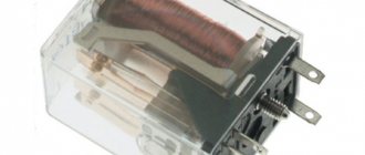
Appearance of an electromagnetic relay
The fact is that the principle of an electromagnet is used in a very important electrical product: an electromagnetic relay.
Let's take a simple electromagnetic relay
Let's see what is written on it:
TDM ELECTRIC is apparently the manufacturer. REC 78/3 - name of the relay. Next comes the most interesting part. We see some stripes and numbers. Contacts 1 to 9 are the relay switching contacts, 10 and 11 are the relay coil.
Now let's talk about everything in order. The relay consists of switching contacts. What does the phrase “switching contacts” mean? These are the contacts that perform the switching. A coil is a copper wire wound around a cylindrical piece of iron. As a result, the solenoid turns into an electromagnet if voltage is applied to its ends.
A little lower we see inscriptions such as 5A/230 V~ and 5A 24 V=. These are the maximum parameters that the relay contacts can switch. It is advisable not to exceed these parameters and take them with a large margin. Otherwise, if the permissible parameters are exceeded, the relay contacts may burn out or burn out completely, which in turn will lead to complete failure of the electromagnetic relay.
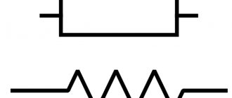
Electromagnetic relays on diagrams: windings, contact groups
The peculiarity of the relay is that it consists of two parts - a winding and contacts. The winding and contacts have different designations. The winding graphically looks like a rectangle, the contacts of different types each have their own designation. It reflects their name/purpose, so identification problems usually do not arise.
Types of electromagnetic relay contacts and their designation in diagrams
Sometimes a type designation is placed next to the graphic image - NC (normally closed) or NO (normally open). But more often the relay affiliation and the number of the contact group are specified, and the type of contact is clear from the graphic image.
In general, you need to look for relay contacts throughout the entire circuit. After all, it is physically located in one place, and its different contacts are part of different circuits. This is shown in the diagrams. The winding is in one place - in the power supply circuit. The contacts are scattered in different places - in the circuits in which they work.
An example of a circuit using electromagnetic relays: the contacts are in the corresponding circuits (see color coding)
For an example, look at the relay diagram. Relays KA, KV1 and KM have one contact group, KV3 - two, KV2 - three. But three is far from the limit. There can be ten, twelve or more contact groups in each relay. And the diagram in the figure is simple. And if it takes up a couple of A2 sheets and there are a lot of elements in it...
Electromagnetic current relays
Current and voltage relays are different, although their structure is similar. The difference lies in the design of the coil. The current relay has a small number of turns on the coil, the resistance of which is low. In this case, the winding is done with a thick wire.
The winding of the voltage relay is formed by a large number of turns. It is usually included in the existing network. Each device controls its own specific parameter with automatic switching on or off of the consumer.
Using a current relay, the current strength in the load to which the winding is connected is controlled. Information is transferred to another circuit by connecting a resistance to it with a switching contact. The connection is made to the power circuit directly or through instrument transformers.
Protective devices are fast and have a response time of several tens of milliseconds.
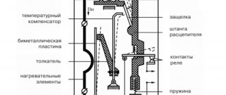
Principle of operation
An electromagnetic relay, the principle of operation of which is common to any type, consists of the following elements:
- Base.
- Anchor.
- A coil of turns of wire.
- Movable and fixed contacts.
All parts are attached to the base. The anchor is rotatable and is held by a spring. When voltage is applied to a coil winding, an electric current flows through its turns, creating electromagnetic forces in the core. They attract an anchor, which turns and closes the movable contacts with paired fixed ones. When the current is turned off, the armature is returned by a spring. The moving contacts move with it.
Only reed relays differ from the standard design, where the contacts, core, armature and spring are combined in a single pair of electrodes.
An electromagnetic relay, the diagram of which is shown below, is a switching device.
It is typical and generally shows how electrical energy is converted into magnetic energy, which then overcomes the spring force and moves the contacts.
The electrical circuits of the coil and switching are not connected in any way. Due to this, small currents can control large ones. As a result, an electromagnetic relay is a current or voltage amplifier. Functionally, it includes three main elements:
- perceiver;
- intermediate;
- executive.
The first of these is the winding, which creates an electromagnetic field. A controlled current passes through it, upon reaching a specified threshold value, an effect occurs on the actuator - electrical contacts that close or open the output circuit.
Time relay
In automation schemes, there is often a need to create delays in the operation of devices or to issue signals for technological processes in a certain sequence. For this purpose, time delay switches are used, which have the following requirements:
- stability of exposure regardless of the influence of external factors;
- small dimensions, weight and energy consumption;
- sufficient power of the contact system.
To control electric drives, high precision requirements are not imposed. The shutter speed is 0.25-10 s. Reliability must be high, since work is often carried out in conditions of shaking and vibration. Power system protective devices must operate accurately. The shutter speed does not exceed 20 seconds. Triggering occurs quite rarely, so high demands on wear resistance are not imposed.
Electromagnetic time relays operate on the following deceleration principles:
- Pneumatic - due to the presence of a pneumatic damper.
- Electromagnetic - with direct current, there is an additional short-circuited winding in which a current is induced, preventing the increase in the main magnetic flux when triggered, as well as its decrease when switched off.
- With an anchor or clock mechanism, which is wound by an electromagnet, and the contacts are activated after counting down the time.
- Motor - supplying voltage simultaneously to the electromagnet and the motor, which rotates the cams that activate the contact system.
- Electronic - using integrated circuits or digital logic.
Electronic relay devices
Recently, analog relays have been replaced by electronic relay devices. They have significant advantages in accurately determining the source voltage, types of applied loads, power and other operating parameters. They are widely used for connecting installations with large power loads. However, their high cost and low reliability prevent them from completely replacing analog devices.
Electronic relay device control of pumping equipment