What is a resistor?
Special components called resistors are designed specifically to create the precise amount of resistance added to a circuit. They are typically made from metal wire or carbon and are designed to maintain a stable resistance value over a wide range of environmental conditions. Unlike lamps, they do not emit light, but they do produce heat because they dissipate electrical energy in a working circuit. Typically, however, a resistor is not designed to generate useful heat, but simply to provide a precise amount of electrical resistance.
Resistor noise and ways to reduce it
The intrinsic noise of resistive elements consists of thermal and current noise. Thermal noise caused by the movement of electrons in the conductive layer increases with increasing heating temperature of the part and the ambient temperature. When current flows, current noise is generated. Current noise, the value of which is significantly higher than thermal noise, is mainly characteristic of non-wire resistors.
Ways to deal with noise:
- The use in the circuit of types of resistors in which the noise is low due to manufacturing technology.
- Variable resistors are noisier than constant ones, so in the circuit they try to use elements with a variable resistance of a minimum value or not use them at all.
- Using retractors with more power than required by the technology.
- Forced cooling of the element by installing a nearby fan.
Symbols and resistor values in the diagram
The symbol for a resistor in the diagram according to GOST is a rectangle measuring 4 mm x 8 mm. In English-language literature, the designation of a resistor in the form of a sawtooth line is common:
Figure 1 – Symbolic graphic designation of a resistor
Resistor ohm values are usually shown on the diagram as numbers next to the symbol, and if there are multiple resistors in the circuit, they will be labeled with a unique identification number such as R1, R2, R3, etc. As you can see, resistor symbols can be shown horizontally or vertically:
Figure 2 – Designation of resistor values in the diagram (150 Ohm and 25 Ohm resistors)
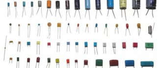
Below are some examples of resistors of different types and sizes:
Figure 3 – Examples of resistors
The diagram can also show that the resistor has a variable and not a fixed resistance. This may be for the purpose of describing an actual physical device designed to provide adjustable resistance, or it may be to show some component that simply has unstable resistance:
Figure 4 – Symbol of a variable resistor
In fact, any time you see a component symbol with a diagonal arrow drawn, it means that the component has a variable value rather than a fixed value. This "modifier" symbol (diagonal arrow) is a standard addition to the identification of electronic components.
Marking of SMD resistors according to EIA-96
SMD resistors with greater precision and smaller dimensions have led to the creation of compact markings. The EIA-96 standard was invented . This standard is designed for resistors with a resistance tolerance of 1%.
This marking system consists of three symbols: the first two digits are the resistor value code, and the next symbol is the multiplier. We take the SMD resistor, look at the first 2 digits and find the corresponding resistance from the table, then look at the number and also look at the table by which to multiply by. It's quite simple.
02A = 200 Ohm ±1%
10S = 1 ohm ±1%
10C = 1000 ohms ±1%
Resistor marking table according to EIA-96 (value codes)
| Code | Number | Code | Number | Code | Number | Number | Number |
| 01 | 100 | 25 | 178 | 49 | 316 | 73 | 562 |
| 02 | 102 | 26 | 182 | 50 | 324 | 74 | 576 |
| 03 | 105 | 27 | 187 | 51 | 332 | 75 | 590 |
| 04 | 107 | 28 | 191 | 52 | 340 | 76 | 604 |
| 05 | 110 | 29 | 196 | 53 | 348 | 77 | 619 |
| 06 | 113 | 30 | 200 | 54 | 357 | 78 | 634 |
| 07 | 115 | 31 | 205 | 55 | 365 | 79 | 649 |
| 08 | 118 | 32 | 210 | 56 | 374 | 80 | 665 |
| 09 | 121 | 33 | 215 | 57 | 383 | 81 | 681 |
| 10 | 124 | 34 | 221 | 58 | 392 | 82 | 698 |
| 11 | 127 | 35 | 226 | 59 | 402 | 83 | 715 |
| 12 | 130 | 36 | 232 | 60 | 412 | 84 | 732 |
| 13 | 133 | 37 | 237 | 61 | 422 | 85 | 750 |
| 14 | 137 | 38 | 243 | 62 | 432 | 86 | 768 |
| 15 | 140 | 39 | 249 | 63 | 442 | 87 | 787 |
| 16 | 143 | 40 | 255 | 64 | 453 | 88 | 806 |
| 17 | 147 | 41 | 261 | 65 | 464 | 89 | 825 |
| 18 | 150 | 42 | 267 | 66 | 475 | 90 | 845 |
| 19 | 154 | 43 | 274 | 67 | 487 | 91 | 866 |
| 20 | 158 | 44 | 280 | 68 | 499 | 92 | 887 |
| 21 | 162 | 45 | 287 | 69 | 511 | 93 | 909 |
| 22 | 165 | 46 | 294 | 70 | 523 | 94 | 931 |
| 23 | 169 | 47 | 301 | 71 | 536 | 95 | 953 |
| 24 | 174 | 48 | 309 | 72 | 549 | 96 | 976 |
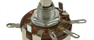
Variable resistors
Variable resistors must have some physical means of adjustment, either a rotating shaft or a lever that can be moved to change the amount of electrical resistance. The photo below shows devices called potentiometers, which can be used as variable resistors:
Figure 5 – Potentiometer
Rated power of resistors
Because resistors dissipate thermal energy as electrical currents through them overcome the "friction" of their resistance, resistors are also rated in terms of how much thermal energy they can dissipate without overheating and causing damage. Naturally, this rated power is indicated in physical units of measurement, “watts”. Most resistors used in small electronic devices such as portable radios are rated at 1/4 (0.25) W or less. The power rating of any resistor is roughly proportional to its physical size. Notice in the first photo of the resistors how the power rating relates to the size: the larger the resistor, the higher the power rating. Also note that resistance (in ohms) has nothing to do with size! While it may now seem pointless to have a device that does nothing other than resist electrical current, resistors are extremely useful devices in circuits. Because they are simple and so commonly used in the world of electricity and electronics, we will spend a lot of time analyzing circuits consisting of just resistors and power supplies.
Inclusion types and usage examples
The main types of connection are serial and parallel connections.
Series resistance is calculated simply. It's enough to put everything together.
In a series connection, the voltage is distributed across the resistors according to their resistances.
This is Kirchhoff's second rule. For example, the voltage is 12 V, and a pair of resistors are 1 kOhm each.
Accordingly, each of them has 6 V. This is a simple example of a voltage divider. Here a couple of parts share the voltage and through this the required voltage can be obtained.
However, if you want to use a voltage divider to power a circuit, you must remember that you need to match the resistances. In this circuit the resistance is 1 kOhm. If you connect a load less than this resistance to it, then it will not receive the full voltage at its terminals. Therefore, all circuits with voltage dividers must be calculated and coordinated with each other.
Let's look at the example of a transistor amplifier.
Here R1 and R2 form a voltage divider, they act as a voltage divider. A current flows between these two resistors and the base of the transistor, which turns on the transistor.
This is necessary for it to work without distortion.
Parallel connection
When connecting radio components in parallel, the overall resistance of the circuit decreases. If two 1 kOhm resistors are connected in parallel, then the total will be less than 0.5 kOhm, i.e. The circuit resistance (equivalent) is equal to half the smallest.
In such a connection, Kirchhoff's first rule is observed. A current of 1 A is sent to the connection point, and at the node it diverges into two directions of 0.5 A each.
Calculation formulas
For two resistors: For more:
For current, a parallel connection is like a second road or bypass. This type of connection is also called bypassing. An example is an ammeter. To increase its reading scale, it is enough to connect another shunt resistor in parallel with the resistor.
Its resistance is calculated by the formula:
Equivalent connection
In the amplifier circuit, a pair of resistor R3 and capacitor C2 is connected to the emitter of transistor VT1.
In this case, VT1 and R3 are connected in series to each other. Why is this necessary? When the amplifier is running, the transistor begins to heat up and its resistance decreases. R3, as in the case of the LED, prevents the transistor from overheating. It balances the total resistance so that the transistor does not distort the signal. This is called thermal stabilization mode.
And capacitor C2 is connected to R3 in parallel. And this is necessary so that during normal operation of the amplifier, the alternating signal passes through without loss. This is how a parallel filter works.
If there was only one R3, then the amplifier's power would be much less due to the fact that it takes the AC voltage onto itself. A capacitor transmits without loss, but does not transmit DC voltage.
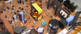
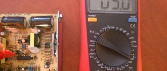
What are resistors useful for?
For a practical illustration of the usefulness of resistors, see the photo below. This is a picture of a printed circuit board: an assembly consisting of insulating layers of fiberglass laminate and a layer of conductive copper traces into which components can be inserted and secured using a low-temperature welding process called "soldering." The various components on this PCB are identified by printed labels. Resistors are designated by any label starting with the letter "R".
Figure 6 – Example of resistors on a printed circuit board
This particular circuit board is an addition to the computer called a "modem" that allows digital information to be transmitted over telephone lines. On the board of this modem you can see at least a dozen resistors (all with a nominal power dissipation of 0.25 W). Each of the black rectangles (called "integrated circuits" or "microcircuits" or "chips") also contains its own resistor array required for operation. Another PCB example shows resistors packaged in even smaller packages called SMD (“surface mount device”). This particular circuit board is the underside of a computer's hard drive; and again the resistors soldered to it are indicated by marks starting with the letter “R”:
Figure 7 – Example of resistors on a printed circuit board
There are over a hundred surface mount resistors on this PCB, and this number of course does not include the resistors built into the black "chips". These two photos should convince anyone that resistors (devices that “merely” prevent electrical current from flowing) are very important components in the field of electronics!
Installation method
According to installation technology, resistors are divided into output and SMD.
Output resistors
Radial output resistor
Axial output resistor
Designed for installation through a printed circuit board. The leads can be located axially or radially. Such parts were used in old audio and video equipment. Now they are used in simple devices and in cases where the use of SMD resistors is impossible for some reason.
The design of output resistors can be made of wire, metal film or composite.
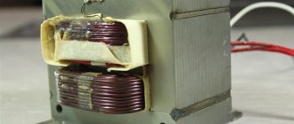
What does a wirewound resistor consist of?
In wirewound resistors, the resistive component is a wire wound around a core. Bifilar winding (two parallel wires insulated from each other, or a regular two-core wire) reduces parasitic inductance. Leads made of stranded copper or brass plates are connected to the ends of the winding. To protect against moisture, mechanical damage and contamination, wire cuts are coated with inorganic enamel that is resistant to elevated temperatures.
What is the difference between a metal film resistor and a wirewound resistor?
In a metal film resistor, the resistive element is not a wire, but a film made of a metal alloy. The resistive components (wire or film) in the resistor are made of alloys with high resistivity: manganin, constantan, nichrome, nickel.
SMD resistors
SMD resistors (or chip resistors) are designed for surface mounting and do not have pins. These miniature parts of low thickness are made in rectangular or oval shapes. They have small contacts soldered into the surface. Their advantages are saving space on the board, simplifying and speeding up the board assembly process, and the ability to use them for automated installation.
SMD resistors are manufactured using film technology. They can be thin- or thick-film. A resistive thick or thin film is applied to an insulating substrate. The substrate performs two functions: a base and a heat-removing component.
What are chip resistors made of?
Thin-film elements, which have special requirements for moisture resistance, are made of nichrome. In the production of thick-film models, ruthenium dioxide, lead and bismuth ruthenites are used.
"Load" on circuit diagrams
In diagrams, resistor symbols are sometimes used to illustrate a general type of device that does something useful with electrical energy. Any unspecified electrical device is usually called a load, so if you see a diagram with a resistor symbol labeled "load", especially in an educational circuit diagram explaining some concepts unrelated to the actual use of electricity, that symbol may simply be some kind of shorthand something even more practical than a resistor.
Resistor Circuit Analysis
To summarize what we've learned in this article, let's analyze the following diagram, determining what we can from the information provided:
Figure 8 – Example circuit
All we are given here to start with is the battery voltage (10 volts) and the current in the circuit (2 amps). We do not know the resistance of the resistor in ohms or the power it dissipates in watts. Recalling the formulas of Ohm's law, we find two equations that give us answers based on the known values of voltage and current:
\(R=\frac{E}{I} \qquad and \qquad P=IE\)
By substituting the known values of voltage (E) and current (I) into these two equations, we can determine the circuit resistance (R) and power dissipation (P):
\(R = \frac{10\V}{2\A} = 5\Ohm\)
\(P = (2\A)(10\V) = 20\W\)
For the given circuit conditions (10 V and 2 A), the resistor should be 5 ohms. If we were to design the circuit to operate at these values, we would have to use a resistor with a minimum power rating of 20 W, otherwise it would overheat and fail.
Why is a resistor needed in an electrical circuit?
A clear example of how a resistor works
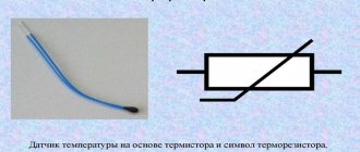
Using a resistor in an electrical circuit, the current is limited, obtaining its desired value. According to Ohm's law, the greater the resistance at a stable voltage, the less the current.
Ohm's law is expressed by the formula U = I*R, in which:
- U – voltage, V;
- I – current strength, A;
- R – resistance, Ohm.
Also resistors work as:
- current to voltage converters and vice versa;
- voltage dividers, this property is used in measuring devices;
- elements to reduce or completely remove radio interference.
Materials from which resistors are made
Throughout the world you can find resistors made from a wide variety of materials, each of which has its own properties and specific applications. Most electronics engineers use the types below.
Wirewound resistors
Figure 9 - Wirewound Resistors
Wirewound resistors are made by winding high-resistance wire in a spiral around a non-conducting core. They are usually used where high precision or high power is needed. The core is usually made of ceramic or fiberglass and the resistive wire is made of nickel-chromium alloy, which is not suitable for applications above 50 kHz. The advantages of wirewound resistors are low noise level and resistance to temperature fluctuations. Resistors are available with resistance values from 0.1 to 100 kOhm and with accuracy from 0.1% to 20%.
Metal film resistors
Figure 10 - Metal film resistors
For metal film resistors, nichrome or tantalum nitride is usually used. The resistive material is usually a combination of ceramic material and metal. The resistance value is changed by cutting a spiral pattern into the film, much like carbon film, using a laser or abrasive. Metal film resistors are generally less stable with temperature changes than wirewound resistors, but cope better with higher frequencies.
Metal Oxide Film Resistors
Figure 11 - Metal Oxide Film Resistors
Metal oxide resistors use metal oxides such as tin oxide, which makes them slightly different from metal film resistors. These resistors are reliable and stable and operate at higher temperatures than metal film resistors. For this reason, metal oxide film resistors are used in applications requiring high wear resistance.
Foil resistors
Figure 12 - Foil Resistors
Developed in the 1960s, the foil resistor is still one of the most accurate and stable types of resistors you will find, used in applications with high precision requirements. The resistive element consists of a thin bulk metal foil, which is glued to a ceramic substrate. Foil resistors have a very low temperature coefficient of resistance (TCR).
Carbon composite resistors
Figure 13 - Carbon Composite Resistors
Until the 1960s, carbon composite resistors were the standard for most applications. They are reliable, but not very accurate (their tolerance cannot be better than about 5%). The resistive element of carbon resistors uses a mixture of fine carbon particles and a non-conductive ceramic material. The resistive substance is shaped into a cylinder and baked. The amount of resistance is determined by the dimensions of the case and the ratio of carbon and ceramics. Using more carbon in the process means lower resistance. Carbon composite resistors are still useful for certain applications due to their ability to withstand high power pulses, a good example application would be a power supply.
Carbon Film Resistors
Carbon film resistors are a thin carbon film (cut in a spiral to increase the resistive path) on an insulating cylindrical core. This design allows for a more accurate resistance value and also increases the resistance value. Carbon film resistors are much more accurate than carbon composite resistors. For applications requiring stability at high frequencies, special carbon film resistors are used.
Key Performance Indicators (KPI)
Key resistor performance indicators for each material can be found below:
Key resistor performance indicators by material
| Characteristic | Metal film resistors | Thick film resistors | Thin Film Resistors | Carbon composite resistors | Carbon Film Resistors |
| Operating temperature range, °C | -55 … +125 | -55 … +130 | -55 … +155 | -40 … +105 | -55 … +155 |
| Maximum temperature coefficient of resistance | 100 | 100 | 15 | 1200 | 250–1000 |
| Maximum voltage, V | 250–350 | 250 | 200 | 350–500 | 350–500 |
| Noise, µV per 1 V applied DC voltage | 0,5 | 0,1 | 0,1 | 4 | 5 |
| Insulation resistance, kOhm | 10 | 10 | 10 | 10 | 10 |
| Change in soldering resistance, % | 0,20 | 0,15 | 0,02 | 2 | 0,50 |
| Change in resistance when exposed to high temperature and humidity, % | 0,50 | 1 | 0,50 | 15 | 3,5 |
| Change in resistance during long-term storage, % | 0,10 | 0,10 | 0,00 | 5 | 2 |
| Change in resistance during operation for 2000 hours at a temperature of 70°C, % | 1 | 1 | 0,03 | 10 | 4 |
Summary
- Devices called resistors are designed to provide precise resistance values in electrical circuits. Resistors are rated by both their resistance (Ohms) and their ability to dissipate thermal energy (W).
- The rated resistance of a resistor cannot be determined by its physical size, although the size can give an approximate value for the power rating. The larger the resistor, the more power it can dissipate without being damaged.
- Any device that uses electricity to perform some useful task is usually called a load. Sometimes the resistor symbol is used in circuits to represent an unspecified load rather than an actual resistor.
Original article:
- Resistors
Purpose
Resistors are a passive element of an electrical circuit that does not convert energy from one type to another. They have active resistance. Their main characteristic is nominal resistance. No less important is a characteristic such as power.
Variable resistors can change their resistance using an accessible adjuster. Act as a current or voltage regulator.
Trimmer resistors have a control that changes the resistance, but it is not available for manual adjustment. To do this you need to use a special screwdriver. These resistors are used only for setting the operating modes of a technical device and are not intended for frequent use.