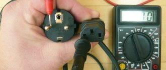
Main stages of testing
Despite the variety of resistors, conventional elements of this class have a linear current-voltage characteristic, which greatly simplifies the test, reducing it to three stages:
- visual inspection;
- the radio component is tested for breakage;
- Compliance with the nominal value is checked.
If everything is clear with the first and second points, then with the last there are nuances, namely, you need to find out the nominal resistance. Having a schematic diagram, this will not be difficult to do, but the trouble is that modern household appliances are rarely equipped with technical documentation. You can get out of this situation by determining the denomination from the markings. We'll briefly tell you how to do this.
What pharmacist malfunctions can you encounter?
You can determine if there is a fault in an element by seeing a distorted image on the screen. This means that the element is highly magnetized. This problem can be resolved by connecting the grid in series with the device. The mesh is the outer loop that covers the inside surface of the screen.
Read also: Checking a car gas cylinder
A posistor is often soldered to the screen. Therefore, it becomes very difficult to check it without disconnecting it from the TV. To take measurements, you need to unsolder at least one part of the device from the grid. But the best solution would be to completely remove the device from the system.
You can heat the posistor with a simple hairdryer. To check the functionality of the device without heating it externally, you need to assemble an electrical circuit. This will help determine the device type. The instructions should state at what voltage the element operates and what temperature it can withstand.
You can determine if the device is working properly by heating it with a hairdryer. If an increase in resistance is noticed, then the element is working. But this method of verification has a drawback - the results may be erroneous. The problem is that the resistance of the parts of the assembled circuit can change over time, and therefore they begin to work unstable.
Another way to determine a posistor malfunction is image distortion. It may ripple, or extra stripes may appear. You can determine the performance of the element using a multimeter. It is recommended that the posistor be cold, since resistance increases when heated.
Another problem is that the contacts have fallen off. With constant heating of the posistor, they begin to wear out, and as a result they fall off. The contacts may look normal on the outside but not work. You can determine their performance using an ohmmeter.
If the posistor is broken or shorted, the fuse will blow the first time you turn on the TV. If there is no short circuit in the network, you need to disconnect the posistor and check its functionality.
Types of markings
On components produced during the Soviet Union, it was customary to indicate the denomination on the body of the part (see Fig. 1). This option did not require decoding, but if the integrity of the structure was damaged or the paint burned out, problems with text recognition could arise. In such cases, you could always turn to the circuit diagram that supplied all household appliances.
Figure 1. “ULI” resistor, the part rating and tolerance are visible on the body
Color designation
Now color marking has been adopted, representing from three to six rings of different colors (see Fig. 2). There is no need to see this as the machinations of enemies, since this method allows you to set the denomination even on a heavily damaged part. And this is a significant factor, given that modern household electrical appliances are not equipped with circuit diagrams.
Rice. 2. Example of color marking
Information on decoding this designation on components is easy to find on the Internet, so it makes no sense to present it within the framework of this article. There are also many calculator programs (including online) that allow you to obtain the necessary information.
Marking of SMD elements
Surface-mounted components (for example, SMD resistor, diode, capacitor, etc.) began to be marked with numbers, but due to the small size of the parts, this information needed to be encrypted. For resistances, in most cases, a designation of three numbers is accepted, where the first two are the value, and the last is the multiplier (see Fig. 3).
Rice. 3. An example of decoding the value of an SMD resistor
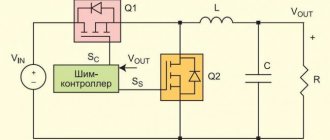
Principle of operation
The operation of any ohmmeter (including modern digital meters) is based on the basic postulate of electrical engineering - Ohm's law. According to its conditions, the greater the resistance, the less current passing through it - at a constant supply voltage.
An ohmmeter requires a power source to operate. A powered electrical circuit is formed in which the device, taking into account the supply voltage and the current flowing through the element being measured, determines the resistance.
Modern digital multimeters use a 9-volt battery.
In China, you can order an 8.4 V nickel-cadmium battery - 7 rechargeable 1.2 V cells, packed in a case of the same size, with a capacity of up to 200 milliamp-hours - it will provide power close to 9 V, which is why the device will not output significant error.
This method is a solution for those who often measure the resistance of resistors, spirals and windings at work, “ring” cable lines, etc.: after about 1000 measurements, a regular battery would “die.”
Digital multimeter
The main feature of a digital multimeter is the presence of a screen; the measured value is clearly displayed on it. The operating principle of the device is based on comparing the measured signal with a reference signal; for this, an analog-to-digital converter is used.
To carry out a measurement, the tester is connected with a set of wires to the element being measured. At one end of each wire there is a plug intended for installation in the meter socket, and at the other there is a contact probe. The procedure for measuring the resistance of a resistor with an electronic multimeter can be represented as the following:
- Pressing the ON/OFF button turns on the device.
- The probes are connected to the two ends of the resistor, the reverse ends of the wires to the Ω and COM connectors.
- The switch sets the approximate resistance.
- If a unit is displayed on the indicator, the switch should be moved up one position, i.e., increase the measurement limit.
- If, when taking readings, numbers other than one are displayed on the screen, this will be the resistance value.
In the same way, you can measure the resistance of the pn junction of a semiconductor. A digital device is convenient to measure constant resistance, but it is useless when you need to find out its variable value. For such measurements, it is preferable to use a pointer instrument.
Pointer device
The very first measuring instruments were equipped with a pointer device. This device was an electromechanical head. Structurally, it is made in the form of a frame located in a magnetic field. An electrical signal is supplied to this head through various resistances. Depending on the current strength, the arrow in the frame deviates, settling in a certain position. The range of the needle deflection is calibrated, according to these values and the required value is calculated.
The technical capabilities of an analog tester are largely determined by the sensitivity of the magnetoelectric measuring device. Its main advantage is its inertia and immunity to interference during the measurement of DC voltage and resistance value.
Pointer instruments are ideal for displaying signal dynamics. The tester instantly shows its change. At the same time, such a device has a large error when measuring in high-resistance circuits, and there is some difficulty in interpreting the measurement results.
The device is turned on according to the instructions indicated on the back of the battery cover. The switch button selects the operating mode for a constant, variable value or resistance (respectively “—”, “~”, “Ω”). A double click is used for a measurement pair. The calculation range switch is set to a fixed value corresponding to the expected measurement value.
Before measuring the resistance value, the tester is adjusted by rotating the zero knob until the arrow points to the “∞” value. When choosing the “Ω” measurement range, the resistance values are not marked with the maximum numbers in this range, but have the following form: x1, x10, x100. This means that the resulting value will be measured in Ohms, kOhms, and MOhms. Active resistance is measured from a direct current source (battery) installed in the device.
Having turned on and prepared the tester, you need to attach the probes to the object being tested. According to the arrow readings, the result will appear on the measuring scale, which is then multiplied by the range multiplier.
Using a Megger
A megohmmeter is a specialized measuring device. Before starting measurements, you must strictly adhere to the requirements of the PUE (electrical installation rules). The basic rules include:
- Measurements are taken at the limit of the tester, which exceeds the highest possible resistance value. If such a value is unknown, then they start with the maximum possible limit, which is reduced to the minimum possible to improve the accuracy of the result.
- Before checking the resistance with a tester, you will need to make sure that the object being tested is de-energized.
- All elements with reduced insulation, capacitors, semiconductors are short-circuited before testing begins.
- During the measurements, the test object is grounded.
- After completing measurements, especially for devices with large capacitance (for example, long-distance wires), before disconnecting the probes of the device, it is necessary to remove the residual charge by shorting it to ground.
- Taking readings of the insulation resistance of power and lighting wiring occurs with switches turned off, fuses removed, and lamps removed.
- It is strictly prohibited to measure insulation near high voltage lines or during a thunderstorm.
A megohmmeter is a complex device consisting of a current generator and a measuring head. Also included are: current-limiting resistors, terminal blocks, a dielectric housing and a mode switch.
The device has three terminals for external connection of wires. The ground is connected to one, the line to the other, and the screen to the third. Which wire is connected where is indicated in the instructions for the device.
The ground and line terminals are used for any insulation readings relative to the ground loop, and the shield contact is needed to reduce the influence of leakage currents. Such currents appear when measuring between two wire strands located parallel to each other. The screen contact is connected with a special wire that comes with the device.
After connecting all the probes on old-style devices, you will need to twist the knob, which will ensure the operation of the internal generator and the supply of voltage to the object being tested. In modern devices, a button is used instead of a handle, and power is taken from installed batteries or galvanic batteries. The generator voltage can range from 100 volts to 2.5 kV. As soon as the voltage is applied, for a pointer instrument, readings are taken from the arrow on the scale corresponding to the selected range, and for a digital type of instrument, readings are taken in the form of numbers on the indicator.
Visual inspection
Violation of the normal operating mode causes overheating of the part, therefore, in most cases, the problematic element can be identified by its appearance. This can be either a change in the color of the case or its complete or partial destruction. In such cases, it is necessary to replace the burnt element.
Figure 4. A clear example of how a resistor can burn out
Pay attention to the photo above, the component clearly needs to be replaced, while the neighboring parts “2” and “3” may be working, but they need to be checked.
General information about resistance
In science, the concept of resistance denotes a physical quantity characterizing the ability of a conductor to impede the passage of an electrical signal flowing in it.
Resistance in an alternating current circuit is called impedance, and in an electromagnetic field it is called wave resistance. There is also an element of the electrical network - a resistor, which is often called resistance. The unit of measurement of a physical quantity is Ohm. On diagrams and in literature, resistance is designated using the Latin letter R.
The most popular method is to check the resistance of a resistor or junctions of semiconductor devices with a multimeter, while special devices are used to measure the wave parameter of a cable, for example, an oscilloscope or an LC meter.
The impedance value of the resistor is indicated on its body by applying numbers or stripes. The actual resistance of a resistor, even a serviceable one, may differ from the nominal value by the value of the permissible deviation. The whole test comes down to measuring the resistance value with a tester and comparing the result with the declared one.
Semiconductors. The operation of semiconductor elements is based on the properties of a pn junction to easily pass current in one direction and resist its passage in the other.
When checking electrical objects, measuring the insulation resistance of wires is of particular importance. Typically, readings are taken relative to the phase conductor and the surface of its insulation. The measuring device used for this is called a megohmmeter.
Checking for a break
Actions are performed in the following order:
- We turn on the device in the “dialing” mode. In Figure 5 this position is marked as “1”.
Rice. 5. Setting the mode (1) and connecting probes (2 and 3) - We connect the probes to sockets “2” and “3” (see Fig. 5). Despite the fact that in our testing polarity does not matter, it is better to immediately train yourself to connect the probes correctly. Therefore, we connect the red wire (+) to socket “2”, and the black wire (-) to “3”.
If the model of the device you are using differs from the one shown in the figure, read the instructions that came with the multimeter.
- We touch the pins of the problematic element on the board with the probes. If the part “does not ring” (the multimeter will show the number 1, that is, an infinitely large resistance), we can state that the test showed a break in the resistor.
Please note that this testing can be carried out without desoldering the element from the board, but this does not guarantee a 100% result, since the tester can show communication through other components of the circuit.
Troubleshooting algorithm
Visual inspection
Any repair begins with an external inspection of the board
It is necessary to examine all components without instruments and pay special attention to yellowed, blackened parts and components with traces of soot or soot. For external inspection, a magnifying glass or microscope can help you if you are working with dense mounting of SMD components
Torn parts may indicate not only a local problem, but also a problem in the strapping elements of that part. For example, an exploding transistor could drag down a couple of elements in the harness.
An area on a board that turns yellow due to temperature does not always indicate the consequences of part burnout. Sometimes this happens as a result of long-term operation of the device; when checked, all parts may turn out to be intact.
In addition to inspecting external defects and traces of burning, it is worth sniffing to check if there is an unpleasant odor like burnt rubber. If you find a blackened element, you need to check it. It may have one of three malfunctions:
- Break.
- Short circuit.
- Not up to par.
Sometimes a breakdown is so obvious that it can be determined without a multimeter, as in the example in the photo:
Checking the resistor for open circuit
You can check the serviceability using a regular dial tone or a tester in diode testing mode with sound indication (see photo below). It is worth noting that by testing you can only check resistors with a resistance of units of Ohms - tens of kOhms. And not every continuity can handle 100 kOhm.
To check, you just need to connect both probes to the terminals of the resistor, it doesn’t matter whether it’s an SMD component or an output one. A quick check can be carried out without desoldering, after which you can still desolder the suspicious elements and check again for a break
Attention! When checking parts without desoldering them from the printed circuit board, be careful - you may be misled by parallel elements. This is true both when checking without instruments and when checking with a multimeter
Don't be lazy and better unsolder the suspicious part. This way you can only check those resistors where you are sure that nothing is installed parallel to them in the circuit.
Short circuit check
In addition to the break, the resistor could have short-circuited. If you use a dial, it should be low-impedance, for example, on an incandescent lamp. Because high-resistance LED dials “ring” the circuit with a resistance of tens of kOhms without significant changes in the brightness of the glow. Sound indicators cope with this test better than LEDs. By the frequency of beeping one can judge the integrity of the circuit; complex measuring instruments such as a multimeter and ohmmeter are in first place in terms of reliability.
Checking for short circuit is carried out in one way, let's look at the instructions step by step:
- Measure a section of the circuit with an ohmmeter, continuity tester or other device.
- If its resistance tends to zero and continuity indicates a short circuit, unsolder the suspicious element.
- Check the section of the circuit already without the element; if the short circuit is gone, you have found a fault; if not, solder the neighboring ones until it goes away.
- The remaining elements are mounted back, the one after which the short circuit is gone is replaced.
- Check the work results for the presence of short circuits.
Here is a clear example that a burnt resistor has left marks on neighboring resistors; there is a possibility that they are also damaged:
The resistor has turned black from the high temperature, not only traces of burning are visible on the neighboring elements, but also traces of overheated paint, its color has changed, and part of the conductive resistive layer could be damaged.
The video below clearly shows how to check a resistor with a multimeter:
Validation check
If the part is soldered, then this stage will guarantee its functionality. For testing we need to know the denomination. How to identify it by markings was written above.
The algorithm of our actions is as follows:
- We connect the probes as in the previous testing.
- We turn on the resistance measurement (the range is shown in Figure 6) in a mode greater than the nominal value, but as close as possible to it. For example, we need to test a 47 kOhm resistor, therefore, we need to select the “200K” range.
Figure 6. Resistance measurement ranges (marked in red) - We touch the terminals with the probes, take readings and compare them with the nominal value. If they do not match, and this can be guaranteed with a probability close to 100%, do not despair. Both the error of the device and the tolerance of the element itself should be taken into account. A little clarification is necessary here.
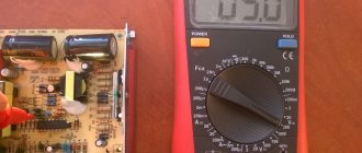
Device settings before measurements
So, friends, let's take a closer look at the device itself. In my case it is a DT9208A digital multimeter. The standard kit includes one pair of probes for force measurements and a thermocouple for measuring temperature, which I have never used before.
There is a rotary switch on the front panel. It is with this switch that the operating mode and measurement range are selected. The switch works like a “ratchet” and is fixed in each new position.
The entire circular panel is divided into sectors and has multi-colored markings (this is in my case). Sometimes sectors are outlined with separate lines, as if separating the required parameter.
The resistance measurement sector is located at the top and is divided into seven ranges: 200, 2k, 20k, 200k, 2M, 20M, 200M. The prefixes "k" and "M" stand for kilo (10 to the 3rd power) and mega (10 to the 6th power), respectively.
To operate, the switch must be set to the desired sector position. We are interested in resistance; therefore, before measuring resistance with a multimeter, we need to set the switch to the sector indicated by the “Ω” icon.
For ease of use with the device, the probes have different colors. It makes no difference where to insert which probe, but the generally accepted rule is that the black probe is inserted into the terminal marked “com” (short for common), and the red probe is inserted into the terminal marked “VΩCX+”.
Before performing any measurements, it is necessary to check the functionality of the device itself, since there may be a break in the measuring circuit (for example, poor contact of the probes). To do this, the ends of the probes are short-circuited with each other. If the device is working properly and there is no break in the circuit, then zero readings will appear on the display. Perhaps the readings will not be zero, but thousandths of an ohm. This is due to the resistance of the test leads and the transition resistance between the probes and their terminals.
When the probes are open, the display will show “1” (one) with a measurement range mark.
These simple steps prepare a multimeter for measuring resistance.
Some multimeters are equipped with a useful option called “diagnosis”. If you set the operating mode switch to the diode icon, a signal (buzzer) sounds when the probes are shorted. This allows you to check the health of circuits and direct junctions of semiconductors with a resistance of up to 50 Ohms by ear, without being distracted by the display.
What is clearance and how important is it?
This value shows the possible deviation of a given series from the specified nominal value. A correctly calculated circuit must take this indicator into account, or appropriate adjustments are made after assembly. As you understand, our friends from the Celestial Empire do not bother themselves with this, which has a positive effect on the cost of their goods.
The result of such a policy was shown in Figure 4; the part works for some time until the limit of its safety margin is reached.
- We make a decision by comparing the readings of the multimeter with the nominal value; if the discrepancy goes beyond the error limits, the part definitely needs to be replaced.
We measure resistance
This is the simplest and perhaps the most popular function of a multimeter in everyday life. In order to measure the resistance, move the arrow to the Ω section and select the setting we need.
Important. Before measuring resistance, be sure to check that there is no voltage on the element. Otherwise, the resistance measurement function of the multimeter will fail.
After this, we lean the ends against the element being measured and see what resistance it gives. If you see the word OVER, it means the setting is extremely low and you need to move the arrow to a higher range.
How to test a variable resistor?
The principle of operation in this case is not very different; we will describe them using the example of the part shown in Figure 7.
Rice. 7. Trimmer resistor (internal circuit marked with red circle)
The algorithm is as follows:
- We take a measurement between legs “1” and “3” (see Fig. 7) and compare the resulting value with the nominal value.
- We connect the probes to terminals “2” and any of the remaining ones (“1” or “3”, it doesn’t matter).
- We rotate the adjustment knob and observe the readings of the device; they should change in the range from 0 to the value obtained in step 1.
Method for measuring electrical resistance - how the device works
The principle by which electrical resistance is measured with a multimeter is based on the most important law of electrical engineering - Ohm's law. The formula we know from a school physics course says the following: the current flowing through a section of a circuit is directly proportional to the voltage (EMF) and inversely proportional to the resistance in this section I (current) = U (voltage) / R (resistance).
It is through this connection that the device operates. Knowing two of the quantities, you can easily calculate the third. The built-in power source (DC) of the device, which is a standard 9 V battery, is used as a voltage source.
Essentially, measurements are performed using an indirect method. If you apply a measured resistance, for example Rx, to the probes of the device, the current flowing in the circuit will depend only on it. Knowing the current and voltage, you can easily calculate the resistance.