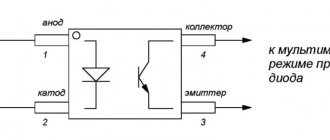
Welcome to the Electrical Circuits resource! Despite the total passion for “userism,” those who like to “tinker” with electronics and design have not yet died out, which is good news. With us, those who have not forgotten how to hold a soldering iron in their hands will find electrical diagrams of domestic and imported televisions, radios and other household appliances, reference information on electronic components, as well as descriptions and diagrams of interesting amateur developments.
In the “News” section you can get acquainted with the latest achievements in the world of electronics, and on the Programs page you can look for software useful for radio designers. All materials are freely available without restrictions and downloading them does not require either registration or “confirmation of humanity.” The only request is not to use materials obtained practically for nothing for selfish purposes.
Thanks in advance and Welcome!
To view documents in .djvu format, you can use the format viewer, which does not require installation and can work from any media. The archive size is 487 KB.
Download
If you have not found the information you need, then a simple feedback form is at your service. Fill it out and we will try to help you. The same form will enable the resource to publish exactly those materials that you would be interested in seeing.
Home » Electronic components » Microcircuits » PWM, for switching power supplies » TNY266PN (PWR original)
Article 450477 Availability:
In stock
Show availability in stores Price: –> Online price: 85.50 pRetail price: 90.00 pQty:
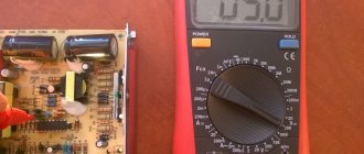
Pulse-width converters are a structural part of switching power supplies for electronic devices. Let's look at how to check a PWM controller using a multimeter, using the example of a computer motherboard.
Check on the motherboard
So, when the board's power is turned on, the protection is triggered. First of all, you need to check the resistance of the stabilizer arms with a multimeter.
- Video, Verkhnaya Salda, Watch online
A radio components tester can also be used for these purposes. If one of them shows a short circuit, that is, the measured resistance is less than 1 Ohm, then one of the key field-effect transistors is broken.
Identifying a broken transistor if the stabilizer is single-phase is not difficult - a faulty device, when checked with a multimeter, shows a short circuit. If the stabilizer circuit is multiphase, and this is how the processor is powered, parallel connection of transistors takes place. In this case, you can determine the damaged device in two ways:
- dismantle the transistor and check the resistance between its terminals with a multimeter for breakdown;
- Without soldering the transistors, measure and compare the resistance between the gate and source in each phase of the converter. The damaged area is identified by a lower resistance value.
The second method does not work in all cases. If the broken element could not be determined, you will still have to unsolder the transistor.
Next, the damaged transistor is replaced, and all radio elements that were soldered off during the diagnostic process are replaced. After this, you can try to start the board.
The first startup after repair is best done by removing the processor and setting the appropriate jumpers . If the first run was successful, you can carry out a load test, monitoring the temperature of the mosfets.
Malfunctions of the PWM controller can manifest themselves in the same way as a breakdown of the mosfets, that is, the power supply goes into protection. At the same time, checking the transistors themselves for breakdown does not give any results.
In addition, the consequence of a malfunction of the PWM controller may be the absence of output voltage or its discrepancy with the nominal value. To check the PWM controller, you should first study its datasheet. The presence of high-frequency voltage in pulse mode, in the absence of an oscilloscope, can be determined using a quartz tester on a microcontroller.
Symptoms of malfunction and their elimination
Let's move on to consider specific symptoms of PWM controller malfunctions.
- TL494CN: converter connection diagram, description in Russian
Stopping immediately after starting
The pulse modulator starts but immediately stops. Possible reasons: open feedback circuit; the power supply is overloaded; The filter capacitors at the output are faulty.
Finding the problem: inspecting the board, looking for visible external damage; Using a multimeter to measure the supply voltage of the microcircuit, the voltage on the switches (at the gates and at the output), and on the output capacitors. In ohmmeter mode, use a multimeter to measure the load of the stabilizer and compare it with the typical value for similar circuits.
Pulse modulator does not start
Possible reasons: presence of a prohibiting signal at the corresponding input. Information should be found in the datasheet of the corresponding microcircuit. The malfunction may be in the power supply circuit of the PWM controller, or there may be internal damage in the microcircuit itself.
Steps to determine the malfunction: external inspection of the board, visual search for mechanical and electrical damage. To check, use a multimeter to measure the voltages on the pins of the microcircuit and check their compliance with the data in the datasheet; if necessary, you need to replace the PWM controller.
Voltage problems
The output voltage differs significantly from the nominal value. This can happen for the following reasons: a break or change in resistance in the feedback circuit; a fault inside the controller.
Troubleshooting: visual inspection of the circuit; checking the levels of control and output voltages and checking their values with the datasheet. If the input parameters are normal, but the output does not correspond to the nominal value, replace the PWM controller.
Disabling the power supply by protection
When the pulse-width modulator starts, the power supply is turned off by protection. When checking the key transistors, a short circuit is not detected. Such symptoms may indicate a malfunction of the PWM controller or key driver.
In this case, it is necessary to measure the resistance between the gate and source of the switches in each phase. A low resistance value may indicate a driver malfunction. If necessary, drivers are replaced.
Switching power supplies – design and repair –>
- Li-ion battery controller circuit
The Complace service center repairs switching power supplies in a wide variety of devices.
How does an inverter work?
RF modulation can be done in three ways:
- pulse-frequency;
- phase-pulse;
- pulse width.
In practice, the last option is used. This is due both to the simplicity of implementation and to the fact that PWM has a constant communication frequency, unlike the other two modulation methods. A block diagram describing the operation of the controller is shown below.
Block diagram of a PWM controller and oscillograms of the main signals
The operating algorithm of the device is as follows:
The reference frequency generator generates a series of rectangular signals, the frequency of which corresponds to the reference one. Based on this signal, a sawtooth UP is formed, which is supplied to the input of the PWM comparator. The signal UUS coming from the control amplifier is supplied to the second input of this device. The signal generated by this amplifier corresponds to the proportional difference between UП (reference voltage) and UРС (control signal from the feedback circuit). That is, the control signal UUS is, in fact, a mismatch voltage with a level that depends on both the current across the load and the voltage across it (UOUT).
Read also: Heat-resistant adhesive for aluminum
This implementation method allows you to organize a closed circuit that allows you to control the output voltage, that is, in fact, we are talking about a linear-discrete functional unit. Pulses are generated at its output, with a duration depending on the difference between the reference and control signals. Based on it, a voltage is created to control the key transistor of the inverter.
The process of stabilizing the output voltage is carried out by monitoring its level; when it changes, the voltage of the control signal UPC changes proportionally, which leads to an increase or decrease in the duration between pulses.
As a result, the power of the secondary circuits changes, which ensures stabilization of the output voltage.
To ensure safety, galvanic isolation between the power supply and feedback is necessary. As a rule, optocouplers are used for this purpose.
Switching power supply operation
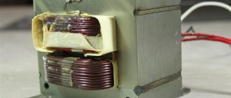
Primary circuit of a switching power supply
The primary circuit of the power supply circuit is located before the pulse ferrite transformer.
There is a fuse at the input of the unit.
Next comes the CLC filter. The coil, by the way, is used to suppress common-mode interference. Following the filter is a rectifier based on a diode bridge and an electrolytic capacitor. To protect against short high-voltage pulses, a varistor is installed after the fuse in parallel with the input capacitor. The resistance of the varistor drops sharply at increased voltage. Therefore, all excess current goes through it to the fuse, which burns, turning off the input circuit.
The protective diode D0 is needed to protect the power supply circuit if the diode bridge fails. The diode will not allow negative voltage to pass into the main circuit. Because the fuse will open and burn.
Behind the diode there is a 4-5 ohm varistor to smooth out sudden jumps in current consumption at the moment of switching on. And also for the initial charging of capacitor C1.
The active elements of the primary circuit are as follows. Switching transistor Q1 and PWM (pulse width modulator) controller. The transistor converts the rectified DC voltage of 310V into alternating voltage. It is converted by transformer T1 on the secondary winding into a reduced output.
And one more thing - to power the PWM regulator, the rectified voltage taken from the additional winding of the transformer is used.
Operation of the secondary circuit of the switching power supply
In the output circuit after the transformer there is either a diode bridge or 1 diode and a CLC filter. It consists of electrolytic capacitors and a choke.
Optical feedback is used to stabilize the output voltage. It allows you to galvanically decouple the output and input voltages. Optocoupler OC1 and integrated stabilizer TL431 are used as feedback actuators. If the output voltage after rectification exceeds the voltage of the TL431 stabilizer, the photodiode is turned on. It includes a phototransistor that controls the PWM driver. The TL431 regulator reduces the duty cycle of the pulses or stops altogether. Until the voltage drops to the threshold.
Repair of switching power supplies
Malfunctions of switching power supplies, repair
Based on the circuit diagram of the switching power supply, we will move on to its repair. Possible malfunctions:
- If the varistor and the fuse at the input or VCR1 have burned out, then we look further. Because they just don't burn.
- The diode bridge burned out. Usually this is a microcircuit. If there is a protective diode, then it usually lights up. They need to be replaced.
- The 400V capacitor C1 is damaged. Rarely, but it happens. Often its malfunction can be identified by its appearance. But not always. Sometimes a seemingly good capacitor turns out to be bad. For example, by internal resistance.
- If the switching transistor burns out, then unsolder it and check it. If faulty, replacement is required.
- If the PWM regulator does not work, then change it.
- Short circuit, as well as breakage of the transformer windings. The chances of repair are minimal.
- An optocoupler malfunction is an extremely rare case.
- Malfunction of the TL431 stabilizer. For diagnostics, we measure the resistance.
- If there is a short circuit in the capacitors at the output of the power supply, then we unsolder it and diagnose it with a tester.
Examples of repair of switching power supplies
For example, consider the repair of a switching power supply for several voltages.
The malfunction was the absence of output voltage at the output of the block.
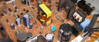
For example, in one power supply two capacitors 1 and 2 in the primary circuit turned out to be faulty. But they weren't swollen.
On the second one the PWM controller did not work.
All the capacitors in the picture appear to be working, but they have high internal resistance. Moreover, the internal ESR resistance of capacitor 2 in the circle turned out to be several times higher than the nominal one. This capacitor is in the PWM regulator circuit, so the regulator did not work. The functionality of the power supply was restored only after replacing this capacitor. Because PWM worked.
Repair of computer power supplies
An example of repairing a computer power supply. An expensive 800 W power supply came in for repair. When it was turned on, the circuit breaker was knocked out.
It turned out that the short circuit was caused by a burnt-out transistor in the primary power circuit. The repair price was 3,000 rubles.
It makes sense to repair only high-quality, expensive computer power supplies. Because repairing a power supply may be more expensive than a new one.
Let's summarize the repair
By the current standards of the crisis and rising prices, someone, a resident of large cities, who has a high salary by Russian standards, can say that God knows what amount was saved, more of their time was spent. But if we return to the fact that there is now another crisis in the yard, saving this amount for most people who know how to hold a soldering iron in their hands, carry out diagnostics of devices and know how to count money, would hardly be superfluous, even if for assembling their own personal system unit. And if so, then people who have experience and practical knowledge in the field of electronics already have an advantage compared to people who do not have this knowledge and, accordingly, do not have this opportunity. Happy repairs to everyone, author of the article AKV.