Fiber Optic Cable Cutting Tool
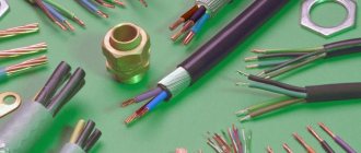
At all stages of work with an optical cable: input control of the fiber optic cable, installation of optical couplings, cross-connects, and so on, an appropriate tool is required for cutting the fiber cable. A set of all necessary tools and materials for cable cutting - NIM-25 (installation tool set) (Fig. 1). The universal kit allows you to mount optical cables with armor made of steel wire, corrugated steel tape, glass rods, including aramid threads and glass fibers, as well as a lightweight universal indoor cable. To cut an optical cable built into a lightning cable (OCGT), it is recommended to complete the kit with a device for cutting a metal module with OM OM SSD.
Rice. 1. NIM-25 Set of tools for cable cutting
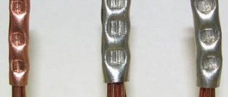
Rice. 2. Knife for metal module
Composition of the NIM-25 kit
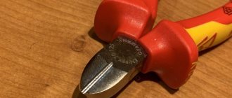
The first group of tools is fairly standard (Fig. 3) from left to right, top to bottom: wire cutters (cable cutters) for cutting steel wire, including various cables and wires, side cutters, sprayer (spray gun), pliers.
Rice. 3. Tool included in NIM-25
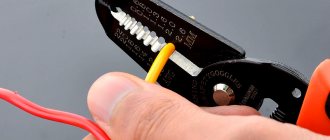
The following group of tools (Fig. 4) from left to right, top to bottom: stripper for removing the buffer, T-type stripper for removing 0.4-1.3 mm (26-16 AWG) sheaths, scissors for cutting reinforcing cable threads, mounting knife.
Rice. 4. Tool included in NIM-25
The third group (Fig. 5), from left to right, from top to bottom: metal tweezers, stripper-clothespin for removing external modules, tape measure, magnifying glass.
Rice. 5. Tool included in NIM-25
A very important and necessary tool when cutting various designs of optical cables is a stripper for removing the outer sheath of the cable (Fig. 6). The depth of the position of its cutting knife is adjusted with a flat screwdriver, depending on the thickness of the shell that we want to cut - first a transverse and then a longitudinal cut is made and then the shell is removed. It is important to remember that during the process of cutting the shell with a stripper, the module with the optical fiber inside must remain undamaged (no cuts, creases, etc.).
Rice. 6. Tool included NIM-25 (stripper for optical fiber)
Auxiliary tools and materials: headlamp, adhesive tape, lint-free wipes, electrical tape, 250 ml alcohol dispenser with pump, D-Gel liquid for removing hydrophobic filler (Fig. 7), set of screwdrivers, hacksaw, container for useful small items ( Fig. 8).
To clean the optical cable from hydrophobic filler, a special liquid D-Gel is used (Fig. 7, right). For ease of work, a rag is moistened with D-Gel and then the mounted cable is wiped with the wet part. After wet wiping, wiping with a dry cloth is necessary. As a result, we get pure OK.
Lint-free wipes are used to wipe optical fibers; in addition, they remove static electricity from the optical fiber.
Rice. 7. Material in the composition of NIM-25
Rice. 8. Tool included in NIM-25
Features of GPON Toolkits
GPON cables typically lack the heavy protective armor found in long-distance fiber optic cables. Therefore, kits for installing GPON networks do not include tools that allow you to cut armor. This circumstance reduces the size and weight of such sets, which is important for work that involves visiting specific subscribers.
A welding machine and a heat shrink oven are usually not included in the case for installing fiber optics. If they are necessary, they are carried separately.
Hobbes HT-F3033 is an example of a fiber optic connector kit containing a variety of consumables
Isopropyl alcohol wipes, abrasives, epoxy resin, and hydrophobic filler remover are consumable items. However, their presence in the set creates certain conveniences. In the tool case, there is a place under them where, as the specified materials are used, you can put new ones, an example of this is the Hobbes HT-F3033.
SK VOLS-3 is a kit that contains testing tools, Kevlar scissors and a special stripper. All of these items are missing from many sets, so VOLS-3 complements them perfectly.
Naturally, a big advantage for the kit is the means of monitoring the quality of the fiber, as well as the created connection. In the simplest case, it is a flashlight and a magnifying glass for visual inspection.
Video: Finding Optical Cable Faults with an Easy-to-Use Tester
A more advanced option is a flashlight (or laser), which produces deep red light, close in wavelength to the infrared range in which information is transmitted. In this light, defects critical to broadband access are more clearly visible. Other monitoring tools that a GPON installer should have include an optical power meter and a fiber break tester. They are included, in particular, in the SK VOLS-3 set.
Optical cable cutting
Working with each type of OC has its own characteristics and nuances that must be taken into account. Below are video instructions for cutting various FOC structures.
DPT cable cutting
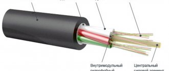
Standard suspended self-supporting optical cable (Fig. 9). Modular twist construction, reinforced with aramid yarns and an intermediate shell.
Rice. 9. Optical cable DPT
Cutting process OK
Using a tape measure, the required cutting length of the fiber-optic cable is measured and the corresponding mark is placed. The outer shell of polymer material is cut (first across the mark, then along OK) with the blade of a Kabifix FK28 stripper (Fig. 6) or another similar tool and then removed. Important note: the stripper adjusted to the thickness of the sheath must first be checked at the OK end (10–15 cm), that is, make sure that the knife does not damage other structural elements of the optical cable.
The reinforcing element in the form of an aramid thread is cut using scissors for cutting reinforcing threads (Fig. 4, bottom left). The intermediate shell is similarly cut and removed using a Kabifix FK28 stripper (Fig. 6). Before starting work, the stripper must be adjusted to the new shell thickness. After removing the intermediate shell, several layers of winding threads are removed from the twisted optical modules (they need to be pryed and cut).
Next, the bundle of optical modules is untwisted, the central power element (CSE) and cords (if any) are cut off to the required length, the entire remaining structure is wiped with a rag moistened with D-Gel liquid (Fig. 7, right).
In the process of working with an optical cable, removing each layer (external, internal, intermediate, strengthening and power elements, etc.), the central power element (CSE) should not break.
The optical module is removed from the bundle of optical fibers using a clothespin stripper (Fig. 5, top right). Using a stripper, you need to make a transverse cut in the module in the right place, then carefully break it and pull it out by its tip. After removing the module, the bundle of optical fibers is wiped with a dry lint-free cloth to remove excess hydrophobe, then the cloth is moistened with isopropyl alcohol (Fig. 7, left) and the bundle of optical fibers is wiped again, but with alcohol.
Video instructions for cutting DPT optical cable:
DPS cable cutting
Standard optical cable for laying in the ground (Fig. 10). Construction with modular stranding, steel wire armor and intermediate sheath.
Rice. 10. Optical cable DPS
Cutting process OK
Using a tape measure, the required cutting length OK is measured and the corresponding mark is placed. The outer shell of polymer material is cut (first across the mark, then along OK) with the blade of a Kabifix FK28 stripper (Fig. 6) or another similar tool and then removed. Important note: the stripper adjusted to the thickness of the sheath must first be checked at the OK end (10–15 cm), that is, make sure that the knife does not damage other structural elements of the optical cable.
The winding thread is removed from the bundle of wire armor. Using cable cutters (Fig. 4, top right), the wire armor is cut to the required distance. The inner shell is wiped with a rag moistened with D-Gel liquid. The intermediate shell is similarly cut and removed using a Kabifix FK28 stripper (Fig. 6). Before starting work, the stripper must be adjusted to the new shell thickness. After removing the intermediate shell, several layers of winding threads are removed from the twisted optical modules (they need to be pryed and cut).
Next, the bundle of optical modules is untwisted, the central power element (CSE) and cords (if any) are cut off to the required length, the entire remaining OK structure is wiped with a rag moistened with D-Gel liquid (Fig. 7, right).
In the process of working with an optical cable, removing each layer (external, internal, intermediate, strengthening and power elements, etc.), the central power element (CSE) should not break.
The optical module is removed from the bundle of optical fibers using a clothespin stripper (Fig. 5, top right). Using a stripper, you need to make a transverse cut in the module in the right place, then carefully break it and pull it out by its tip. After removing the module, the bundle of optical fibers is wiped with a dry lint-free cloth to remove excess hydrophobe, then the cloth is moistened with isopropyl alcohol (Fig. 7, left) and the bundle of optical fibers is wiped again, but with alcohol.
Video instructions for cutting DPS optical cable:
Cable termination DOL
Standard optical cable for installation in cable ducts (Fig. 11). Design with modular twist and steel tape.
Rice. 11. Optical cable DOL
Cutting process OK
Using a tape measure, the required cutting length OK is measured and the corresponding mark is placed. The outer shell of polymer material is cut across the mark using a Kabifix FK28 stripper blade (Fig. 6) or another similar tool. Important note: the stripper adjusted to the thickness of the sheath must first be checked at the OK end (10–15 cm), that is, make sure that the knife does not damage other structural elements of the optical cable.
Then, using a Kabifix FK28 stripper or a mounting knife, transverse cuts are made (from the end of the cable) and the sheath of the optical cable, together with the steel tape, is pulled towards the OK end. To facilitate the process of tightening the shell with the armor, it is recommended to make transverse cuts every 20–30 cm. After removing the shell with the tape, several layers of winding threads are removed from the twist of the optical modules (they need to be pryed and cut) and the water blocking tape.
Next, the bundle of optical modules is untwisted, the central power element (CSE) and cords (if any) are cut off to the required length, the entire remaining OK structure is wiped with a rag moistened with D-Gel liquid (Fig. 7, right). If there are cordels in the design, they are bitten off.
In the process of working with an optical cable, removing each layer (external, internal, intermediate, strengthening and power elements, etc.), the central power element (CSE) should not break.
The optical module is removed from the bundle of optical fibers using a clothespin stripper (Fig. 5, top right). Using a stripper, you need to make a transverse cut in the module in the right place, then carefully break it and pull it out by its tip. After removing the module, the bundle of optical fibers is wiped with a dry lint-free cloth to remove excess hydrophobe, then the cloth is moistened with isopropyl alcohol (Fig. 7, left) and the bundle of optical fibers is wiped again, but with alcohol.
Video instructions for cutting optical cable DOL:
See the Knowledge Base for video instructions on cutting optical cables with other designs.
Laying fiber optic cables: methods, techniques, problems
Koloskov A. A., “The Cable Guy”, No. 1/2 (16)
Introduction
Fiber-optic communication lines (FOCL), due to a number of advantages and disadvantages (low attenuation, ultra-wideband, electromagnetic noise immunity, etc.) over traditional lines based on electrical cables, can provide a significant effect in the construction of new and modernization of existing cable communication systems. But no winnings or advantages are given for nothing. Fiber optic technology requires a more delicate attitude, greater knowledge and a high production culture.
The fiber-optic fragment in the structure of cable information transmission systems, among others, is designed to solve the problem of long distances, which is very important for vast Russia. With the steady decline in prices for fiber-optic equipment, including cable products, the laying and installation of optical cables is currently becoming widespread.
This article, which discusses simple but necessary things, is the result of a generalization of the experience of the installation department. The article is addressed not to “seasoned” specialists, but to young installation departments that have recently joined the large and motley family of “cable workers”.
Normative base
The construction and operation of fiber-optic lines is carried out in accordance with the requirements stipulated in the following regulatory documents:
1.
Guidelines for the construction of linear structures of trunk and intrazonal cable communication lines. – Moscow, 1986
2.
Guidelines for the construction of linear structures of local communication networks. M., JSC "SSKTB - TOMASS", 1995. Approved by the Ministry of Communications of Russia on December 21, 1995.
3.
Guidelines for laying, installing and commissioning optical communication lines of the GTS. – Moscow, 1997
4.
Manual for the operation of line-cable structures of local communication networks. M., UES of the State Committee for Communications of Russia, 1998. Approved by the State Committee for Communications of Russia on June 05, 1998.
5.
Standards for acceptance and acceptance measurements of elementary cable sections of trunk and intrazonal underground fiber-optic transmission lines of a public communications network. Approved by order of the State Committee for Communications of Russia No. 97 dated December 17, 1997.
6.
Regulations on the organization of electrical measurements during installation and commissioning of fiber-optic lines at the Moscow GTS. Approved by the management of JSC MGTS and JSC Mostelefonstroy in October 1995.
7.
Installation and measurements of fiber-optic communication lines. A manual for fiber optic line meters and installers. OJSC "Mostelefonstroy" 1999
8.
GOST 25462-82. Fiber optics. Terms and Definitions.
9.
GOST 26599-85. VOSP components. Terms and Definitions.
It will be very useful to familiarize yourself with the modern Technical Specifications (TS) for fiber-optic cables from leading manufacturers.
Features of the construction of fiber-optic communication lines
The main stages of construction of communication lines on electrical and optical cables are the same. This makes it possible to widely use well-known techniques and mechanisms in the process of building fiber-optic lines.
Differences in construction technology, installation work and operation of fiber-optic lines are due to the following design features of the optical cable (OC):
- relatively low resistance to tensile and compressive forces;
— small transverse dimensions and weight in combination with large construction lengths;
— relatively large attenuation values of optical fiber (OF) splices;
— difficulties in organizing official communications;
— the need to spend large amounts of time on operations for splicing OM, as well as increased requirements for personnel qualifications.
The fundamental point is to ensure the least stressful conditions possible when laying the casing. The physical limitations recommended by the manufacturer must be strictly followed.
In general, the process of laying OK consists of two stages: preparatory and main (the laying itself).
The preparatory stage includes incoming inspection of construction lengths. Incoming inspection of construction lengths consists of external inspection of the cable and measurement of its optical characteristics. Drums with OK are subjected to external inspection for the absence of mechanical damage. After opening the drum casing, the presence of factory passports is checked, the compliance of the construction length markings indicated in the passport with the markings indicated on the drum, as well as the external condition of the cable for the absence of dents, cuts, pinches, twists, etc.
When measuring optical characteristics, first of all, the kilometer attenuation of the optical device is determined, i.e., its OF, and the results are compared with the passport data. In case of unsatisfactory results of the incoming inspection, a report is drawn up against which a complaint is made.
Pulling cables in the sewer
Fiber optic cable outside buildings within populated areas is laid in most cases in telephone sewers. It is based on round pipes with an internal diameter of 100 mm made of asbestos cement, concrete or plastic. Telephone sewerage is laid at a depth of 0.4 to 1.5 m from separate blocks hermetically joined together. After 40-100 m, inspection wells are placed on the route, on the walls of which consoles for cable laying are mounted. The difference between the technology for laying electrical and optical cables in telephone ducts is that the pulling force of the latter should not exceed the permissible value, and cable torsion is not allowed.
Cable laying in a telephone sewer is usually carried out in a free channel, where during construction a wire is left for pulling. In its absence, the passage of channels is carried out using a channel preparation device, which is an elastic fiberglass rod with a diameter of 10 mm and a length of up to 150 m, wound on a drum with a diameter of about 1 m. The rod is pushed into the channel to the adjacent well. Next, attach the end of the cable to the tip of the rod and pull it back. For fastening, you need to use a special tip, which is fixed on the cable by its strength element and armor covers and must be equipped with a torsion compensator. Pulling should be done smoothly and without jerking.
If there are sharp turns on the route, a rotary roller is installed in the well. In its absence, the cable is pulled out of this well in a loop, and further installation is carried out as from the starting point of the route. Often, to save construction time, the cable is sorted by hand directly in the well, directed into the sewer pipe.
Cable laying in buildings
Laying OK is usually not very difficult, both because of the short length of the route and because of the lighter and more flexible design of the intra-facility cable used for this. In the case of installation in pipe distribution, under a false floor and behind a false ceiling, the cable is first unrolled from the transport drum and laid out in a loop or figure eight at the starting point of the route, and then smoothly pulled into the cable channel. To facilitate the work, steel broaching wire 5-10 m long can be used.
When laying cables on open cable racks or in gutters in long corridors, it is more convenient to lay the cable on the floor along the route, and then lift it onto the gutter and fix it with plastic clamps every 2-3 m.
In non-residential attics and technical floors of buildings (if they are through), it is very convenient to hang the cable using standard metal hangers on a pre-tensioned support cable. In this case, complex strength calculations taking into account wind and ice loads are usually not required. The same method can be recommended when laying cables through basements and technical undergrounds of buildings in the absence of existing cable channels.
Air cable suspension
OK suspension options have a number of advantages compared to other construction methods:
— no need for land allocation and approvals from interested organizations;
— reduction of construction time;
— reducing the amount of possible damage in urban areas and industrial zones;
— reduction of capital and operating costs;
— independence from types of soils and soils.
However, there are also disadvantages of air laying:
— shorter service life due to environmental influences;
— susceptibility to increased mechanical stress in adverse weather conditions;
- unaesthetic;
— the complexity of calculations when exposed to loads under all operating conditions.
For the construction of fiber-optic lines using the suspension method in populated areas, the OK suspension to a steel cable stretched between supports on consoles, as well as the OK suspension with a built-in cable on specially designed consoles, are widely used. When hanging the OK from a steel cable, each console is attached to the support with special screws. The installation height of the consoles (taking into account the normal sag) must be such that the clearance from the ground to the lowest point of the cable is at least 4.5 m. The OK is attached to the cable using hangers made of galvanized sheet steel. The hangers must tightly cover the OK and move freely along the steel cable.
When suspending OK with a built-in support cable, standard power supply fittings of the KGP type and a supporting clamp PSO-14-03 are used. For tension fastening of a self-supporting OK, a spiral clamp of the NSO-14P-02 brand is used. The fastening of this clamp to the support is carried out through the thimble supplied with the clamp and the linear coupling fittings. Re-installation of the spiral support and tension clamps is prohibited.
The figures below show the fittings for tension and support fastenings OK on supports of a circular cross-section.
Schemes for fastening non-self-supporting dielectric OC on round supports
Rice. 1 Tension fastening diagrams OK
Rice. 2 Schemes of supporting fastening OK
Schemes for fastening a self-supporting dielectric OC on round supports
Rice. 3 Scheme of tension fastening of a self-supporting OK
Rice. 4 Scheme of supporting fastening of a self-supporting OK
As mentioned above, the disadvantages of the OK air suspension include the difficulty of calculating all the loads acting on the air-cable transition (ACT). The calculation of the supporting cable includes the calculation of the actual tension force under operating conditions, which should not exceed the ultimate tensile strength of the cable, and the calculation of the required length of the cable. The ultimate tensile strength of the cable and its specific gravity can be found in the manufacturer’s technical documentation. When calculating the cable tension, it is necessary to take into account all components of the load that can affect its stretching in real conditions, i.e., calculate its total weight load. In the worst case, the cable stretches under the influence of its own weight, the weight of the cable and fastening structure, and the weight of freezing ice (the vertical component of the load). In addition, the load on the cable increases under the influence of wind force (horizontal component of the load). The required length of the cable must be calculated taking into account the sag, which changes depending on temperature fluctuations and tension force.
As practice shows, the reliability of cable laying on a suspension can be guaranteed when using a cable whose tension does not exceed 60% of its ultimate tensile strength (in all operating conditions). The issues and methodology for fully calculating aerial-cable transitions are quite complex and are not presented in this article. Some formulas and considerations are presented in an accessible and understandable form in [6, 7].
Optical cable cutting
Cutting an optical cable includes the steps of removing the outer covers and cutting the core.
In the process of cutting an optical cable, armor coverings, protective shells are removed and light guides are prepared for installation of connectors or splicing by welding. During cutting, the cable must be firmly fixed on the mounting table with a clamp, clock vice or plastic tie.
The purpose of cutting is to prepare the light guides for welding or installation of connectors. The cutting length is usually about 1 m when using welded technology.
Removal of the outer protective hose begins by making a circular cut on its shell. The distance from the edge of the cable to the cut point should be equal to the cutting length. The protective hose is then cut longitudinally using a breaking thread or a knife. If there is no breaking thread in the cable design, the use of a special cable knife with a self-orienting or rotary cutter gives a good effect.
The internal protective hose is removed from the cable core in the same way as the external one using a breaking thread, a regular or cable knife. The core elements are unraveled, the end of the cable is firmly fixed on the mounting table with a clock vice, cable ties or a clamp. The threads of the reinforcing Kevlar winding are cut off with scissors, the reinforcing elements are removed with side cutters, the central power steel cable is cut with cable cutters or sawed through with a hacksaw.
To remove module tubes, a stripper or a special ring knife is used. A circular cut is made on the sheath with a tool, then the tube is removed from the fiber using a smooth, constant pulling force. To reduce the forces acting on the fibers, the module tubes are removed in several stages.
After removing the module's protective tube, the fibers are cleaned of the hydrophobic gel with a rag or napkin soaked in a special cleaning liquid or alcohol. The processed fiber is set aside. Then they begin cutting the next module.
The completely cut cable is inserted into the switching and cutting device, and after being fixed in it, it is ready for further work.
Basic safety rules when working with fiber optic devices
When working with optical cable and other fiber-optic equipment, you must:
1.
Under no circumstances should you look into the end of the optical fiber or optical transmitter connector. The radiation transmitted through the light guide is outside the visible wavelength range, but can lead to irreversible damage to the retina.
2.
Avoid getting optical fiber scraps generated during connector installation and fiber splicing on clothing or skin. These trimmings should be collected in tightly sealed containers or with sticky tape. When working with fiber, it is necessary to wear safety glasses.
3.
While working with optical fiber, eating is strictly prohibited, and after work you must wash your hands with soap.
4.
Please be aware that alcohol and solvents used to remove protective coatings are flammable and burn with a colorless flame and may be toxic and cause an allergic reaction.
5.
Welding machines use high voltage to form an electric arc, which is dangerous to life, and the arc discharge between the electrodes can lead to the ignition of flammable gases and vapors of flammable liquids.
6.
Smoking while working with fiber optics can lead to a sharp decrease in the quality of the weld or the manufactured connector.
Useful tips (extract from the Technical Specifications for optical communication cables, section: Installation and operation instructions):
— the cables are intended for laying (installation) at a temperature not lower than minus 10° C;
— the bending radius of the cable during installation (installation) must be at least 20 nominal outer diameters of the cable;
— when installing the cable, the permissible tensile and crushing loads, as well as other mechanical characteristics, the values of which are specified in the Technical Specifications, must not be exceeded;
— permissible static bending radius of optical modules – at least 40 mm;
— permissible bending radius of the optical fiber during installation is at least 3 mm (within 10 minutes);
— organizations carrying out cable laying and installation must have a valid certificate for the right to carry out the relevant construction and installation work.
When laying (installing) and operating cables intended for suspension on overhead communication lines, the following special requirements must be observed:
— when unwinding the cable during installation, the cable must not touch any objects, with the exception of rotating rollers;
— the radius of the mounting rollers installed on the first support must be at least 20 nominal outer diameters of the cable;
— in the process of laying the boom, the sag should be greater than the design values. Installation of the design sag booms should be carried out at the final tension of the cable;
— technical characteristics of suspension fittings must be agreed with the cable manufacturer;
— during operation, the cables must be protected by vibration absorbers from vibration that occurs under wind load.
BIBLIOGRAPHY:
1.
A. B. Semenov, “Fiber optics in local and corporate communication networks.” – Computer press, Moscow, 1998
2.
R. Freeman, “Fiber Optic Communication Systems.” – Moscow: Tekhnosphere, 2003. – 440 p.
3.
“Fiber-optic communication systems on GTS.” – Directory. Ed. A. S. Briskera, A. N. Golubeva. – M.: “Radio and Communications”, 1994.
4.
"Fiber optic technology: Current status and prospects." – 2nd ed., revised. and additional / Sat. articles edited by Dmitrieva S. A. and Slepova N. N. - M.: Fiber Optical Equipment LLC, 2005 - 576 p.
5.
Z. A. Zima, I. A. Kolpakov, A. A. Romanov, M. F. Tyukhin, “Cable television systems.” – Publishing house of MSTU im. N. E. Bauman, Moscow, 2004
6.
S.V. Volkov, “Cable TV networks.” – M.: Hotline-Telecom, 2004 – 616 p.
7.
“TFC cables. Methodology for calculating cable tension during aerial laying.” – J-l TELE-Sputnik, February 2000
8.
Optical communication cables. Technical conditions. TU 3587-009-48973982-2000.
9.
Website – www.ssd.ru.