When the light goes out in the house, people behave differently, since for some it is simply the inability to watch TV, but for others it is a blocking of activities, especially if a person has some kind of workshop equipped with electrical appliances. It is clear that in the second case, automatic switching on of the generator during a power outage will be an urgent need. And in this article we will talk specifically about automatic, rather than manual, starting of the reserve.
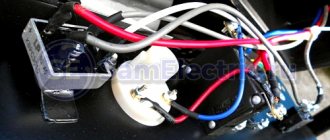
The unit has manual and automatic start functions Source daewoo-sales.com.ua
Model range and prices.
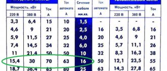
Expert - the main line of RUENERGY, includes 3 models. Supplied in a plastic case with protection against dust and precipitation IP65. Designed for both outdoor and indoor installation. Schneider Electric components. The control element is replaceable 105/207/200. Without changing the equipment, change the functionality!
| Expert | 4-pole | Built-in | Professional |
| E105-38/3-P Schn | E207-63/3-P ABB (4) | 105-63/3 ABB | E200-63/3-M (4) ABB GSM |
| E105-65/3-P Schn | E207-45/3-P Schn (4) | 105-38/3 Schn | E200-45/3-M (4) Schn GSM |
| E105-95/3-M Schn | 105-65/3 Schn |
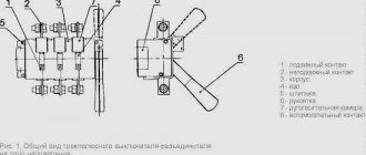
Description of possible ABP connection methods
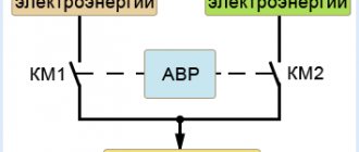
Relationship between contacts KM1 and KM2 Source asutpp.ru
When connecting a generator with auto-start, the most important thing in this process is to take care to exclude the slightest possibility of counter currents entering the circuit. This can happen if the contactors operate incorrectly, that is, power will come from two sources. At the top there is a simple diagram with terminals K1 and K2, which should always be in different positions. When one turns on, the other necessarily opens and vice versa. At the moment, you can find more than one diagram on the Internet indicating how autostart occurs for a gas generator, but the general principle, taking into account the position of K1 and K2, will never change.
The principle of connecting the reserve input never changes Source asutpp.ru
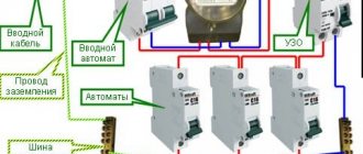
Also, the location of the ABP on the diagram never changes, although physically it can be hung anywhere - even on the ceiling. The essence of the insert is that the machine will always be between the electricity meter and the substation, and no one will install it after the meter, so that you do not have to pay for the electricity that you yourself produce.
Schematic diagram for a private house Source asutpp.ru
When it comes to a private home, an autostart for a generator can be assembled according to the diagram above. Yes, you see exactly the fundamental warrant for the ABP installation, but in order to draw up a specific installation diagram, you need to know exactly the location, type and power of the equipment that should be started from the reserve. So, if you show a little ingenuity, you can tailor this scheme to the needs of your building and the electrical appliances located in it.
Detailed connection diagram for ATS Source asutpp.ru
Designations
| E – Energy, manufacturer. 105 - control element (controller) | Schn – manufacturer of components P/M – plastic/metal, body material |
| 38 – contactor rated current 3 – number of controlled network phases | (4) — four-pole contactor (3ph+N) GSM – presence of a message sending module |
4-pole – a line for demanding customers. ATS panel with four-pole contactors and separated neutrals. Supplied in an IP65 plastic box. Control controller Datakom 207. The main feature is complete shutdown of the network/generator, three phases and neutral. Built-in – the widest line of RUENERGY ATS. Consists of 4 models built into casings of the Silent and Super Silent series. Upon request, such an ATS kit can be built into the existing input panel of your country house. An engineer will come and assemble the autostart right in your box. To do this, you need a space in the input panel of at least 30*40*12 cm (W x H x D). There is no need for laying cable lines or construction work. Professional – the flagship line of RUENERGY. Supplied in an IP54 metal housing. Control element D200. It has a built-in GPS module for determining coordinates, a GSM (GPRS) module for remote control via an application or from a computer, and SMS/E-mail notification. Load control for each phase thanks to current transformers makes it easy to balance the network and control the load on the generator. The controller has high IP protection and can be installed outdoors with temperatures down to -40 (the LCD display has built-in heating). All network parameters are available online.
Popular models of generators with automatic transfer switch [ view... ]
About AVR schemes
There are several different schemes for implementing ATS. Next I will write about the safest, from my point of view, single-phase ATS circuit. I do not advise economically making an ATS on one contactor or with switching only one phase wire. Only together with neutral.
In the diagram shown, power from the network and from the generator is supplied through inputs 1 and 2. They are protected by paired circuit breakers. The switching and indication circuits are powered through additional circuit breakers. It can be seen that the relay coils are electrically interlocked. For the sake of simplicity, a microcontroller not shown in the diagram, which closes the circuits at the switching point TK1 or TK2, is responsible for turning on one or another input.
The fundamental point is the presence in the ATS of 2 interlocking circuits - mutual mechanical interlocking of the contactor switching inputs and mutual electrical interlocking of the contactors. In order to save money, home-made people sometimes neglect these blockings in their designs, but in vain. A circuit without interlocks can work for some time, but at some point the contacts will burn, the return springs will weaken and a short circuit will occur between the inputs. Firstly, it threatens a big bang if both lines are energized, but this is not the biggest problem. It is much more important that your generator, unexpectedly for the electricians repairing the wiring, can release voltage into the general network - in an unfavorable combination of circumstances, the electricians repairing the line may die. For you this is already a criminal article.
Manual network control panels
| Model | price, rub. | |
| E40-4 (ABB) | 16 000 | |
| E63-4 (ABB) | 18 000 | |
| Includes everything needed to operate the generator. The indication allows you to accurately determine the presence of voltage from the network or generator. Pulse charging of the battery allows you to use the electric unit even in winter without removing the terminal or battery for charging. Reversing switch 4-pole, with additional contacts. The panel has a 16 A socket. The box with IP 65 protection can be installed outdoors. | ||
What is an AVR and its purpose?
Automatic transfer switching or ATS is a system related to electrical switchboard input and switching distribution devices. The main purpose of the ATS is to quickly connect the load to backup equipment. Such a connection is necessary when problems arise with the supply of electricity from the main power source. The system monitors the load voltage and current and thus ensures automatic switchover to emergency operation.
ATS is necessary if there is a spare power source (an additional line or another transformer). If during an emergency the first source is turned off, all work will transfer to the spare one. Using an ATS will help you avoid troubles caused by power outages.
Requirements for ATS
The main requirements for ATS systems are as follows:
- It must have a high rate of power restoration.
- In the event that the main line stops working, the installation must provide electricity to the consumer from a backup source.
- The action is carried out once. Multiple switching on and off of the load, for example due to a short circuit, should not be allowed.
- The main power switch must be turned on using the automatic transfer system. Until backup power is supplied.
- The ATS system must monitor the correct functioning of the backup equipment control circuit.
Advantages
This block describes the main advantages that differ from third-party manufacturers and relate directly to the automation units themselves, their technical and operational components.
| Starts at any ambient temperature. More than 60% of manufacturers use a drive from the car's central locking device as an actuator. Retail cost 100 -120 rubles. The drive has limited travel and only 2 positions. Startup is unstable, especially during cold periods. RUENERGY equipment uses an actuator of its own design. Control unit + servo drive. Starting at any temperature is achieved by precisely adjusting the choke position. With each adaptation, three damper positions are calibrated. Programming is carried out if necessary. Calibration and programming are done manually, without using a computer. |
| Versatility. Thanks to the ability to precisely adjust the position of the air damper, RUENERGY ATS units can be used on any generator model with an electric starter. Only the set of mounts changes for different types of engines. That's why we have such a wide range of electric generators with autostart. The basis is well-known, proven manufacturers: Honda, Robin-Subaru, Briggs and Stratton, Kohler. The operating algorithm of the carburetor air damper drive allows the electric generator to be started equally well both in “cold” and “hot” conditions. The thermal diode built into the board regulates the opening time of the air damper depending on the ambient temperature. |
| High-quality components and bench testing. Many manufacturers save on components, relying on a one-year warranty and use Chinese modular contactors, IEK, Metasol, etc. However, as experience shows, the Chinese save on everything, including the cross-section of conductive parts, as a result of which the starters begin to heat up. RUENERGY uses components from proven and proven manufacturers - Schneider Electric, ABB. All switchboard equipment undergoes bench testing, along with the generator. Tests are carried out under load in the main areas: voltage drop or phase loss, testing by the actuator of algorithms for starting the generator set. |
| Replacement panels for the Expert line. In the Expert line, all panels are interchangeable, from the simplest and most intuitive DKG 105 to the professional D-200 with the ability to remotely monitor and control. It is enough to replace the panel and you will get new features and functionality. The delivery set contains all the necessary diagrams: connection diagrams for all network configuration options, as well as a circuit diagram. Accordingly, in the switchboard itself, all inputs and outputs are marked according to the diagrams. The connection can be carried out by a specialist with experience and appropriate approval for electrical safety; an operating manual is provided for the user. You can download it in the product card of a specific model. |
| Remote control and GSM module. Autostart units of the “Expert” and “Pro” lines with the D-200 controller support remote monitoring and control of all available parameters from incoming voltage to harmonics in the network. The module is capable of notifying about any changes in network operation via SMS or E-mail. Control from a mobile phone is carried out via an application (Android) or browser. Control from a computer is carried out via a browser or the Scada Rainbow program via the RS-485 protocol. The GSM module works via a SIM card via GPRS. The controller has a GPS module that performs positioning on the ground. The controller has an LCD display and can be installed outdoors at temperatures down to -40 degrees Celsius (equipped with a heater). |
About the control scheme
When I was creating an AVR, I had several special requirements for its operation:
- My electricity doesn’t go out that often, so I decided that I didn’t need the autostart of the generator, but I decided not to give up the automatic stop of the generator: when the network is restored, the generator itself goes quiet and it’s immediately clear that now everything is fine with the power supply, and gasoline is saved
- After starting the generator, you need to give it time to warm up and only after warming up give it a load. Those. I needed a timer to turn on the ATS after applying voltage from the generator
- After the network voltage was restored, repeated outages often occurred after a short period of time, so I needed a timer that would wait a while before switching from the generator to the network and would not immediately turn off the generator
- They say it is useful for the generator to run a little without load before turning it off. And for this I also needed a timer
Thus, the picture emerged that I needed a controller with several timers.
At that time, I was interested in coding on AVR, so I decided to make such a controller on Atmega 8a. It would be nice if the controller worked for a long time and reliably. Besides, I couldn’t think of anything else to make a complete galvanic isolation and equip the controller with a watchdog timer. Well, make the diagram and program as simple as possible. Since I was doing everything for myself, I decided to leave all the settings and calibrations in the code - the entire UI was reduced to one LED)
The main task of the controller is to monitor the voltage at the inputs and, if necessary, switch the inputs. In this case, input from the village network has priority.
It is worth noting here that the quality of the network is such that fluctuations from 150 V to 250 V are quite common. Therefore, the concept of good mains power is very vague. After some time, I solved this problem when I installed one powerful 11 kW thyristor voltage stabilizer for the whole house. But, it’s important, the stabilizer can only be installed before the AVR, and not after! It is strictly not recommended to turn on the stabilizer for the generator. There is a danger that under a certain combination of loads, especially any powerful pumps, the system of a generator and stabilizer will become unstable and enter into self-oscillations.
After some thought, I drew such a diagram in Eagle.
The circuit has two identical transformer power supplies; if there is voltage at any of the inputs, the circuit is provided with power. A voltage of 600V is possible between the inputs, so the insulation of the transformers must be good. Power is taken after the QF3 and QF4 packets, respectively.
Each source has a resistive voltage divider, protected from overvoltage by a zener diode - from it, the network voltage is measured using a microcontroller ADC using simple calculations.
To switch the contactor coils, a standard circuit from the datasheet is used to control semistores. 2 pieces ). Coils are an inductive load, so snubber circuits at the resistor and capacitor output are required.
I had a relay module with Ali that is used to stop the generator. In the diagram it is just a rectangle with three pins.
Among the features, the TL431 is also used as a reference voltage generator. Otherwise, everything is included as standard for Atmega 8. There are LEDs to indicate the presence of supply voltage at the inputs and one device status LED. The circuit is clocked using an external quartz at 16 MHz.
Eagle gave me this printed circuit board. No SMD, triacs and stabilizer with light radiators.
Two toroidal transformers are installed directly on the board. The board was made using the traditional amateur radio method using photoresist. After installation, I covered it with three layers of acrylic varnish. I hope the high voltage doesn't break through.
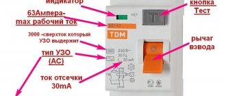
Technical characteristics of the AVR shield
| Specifications | Meaning |
| Rated voltage, V | 220; 380 |
| frequency Hz | 50 |
| Rated current, A | 16; 25; 40; 63; 100; 160; 250; 400; 630 |
| Type of climate control panel | UHL 3.1 according to GOST 15150-69 |
| Switching time, s no more | 0.2 |
| Controlled parameters | Loss of at least one of the phases; symmetrical or asymmetrical reduction in voltage of one of the phases; change of phase sequence |
How to automate generator startup?
The generator start automation system only works with generators equipped with an electric starter. If your generator does not have an electric starter, then you can check with the generator manufacturer whether it is possible to purchase and install an electric starter.
Fig 2. Honda generator electric starter.
When starting, the engine is spun by a commutator electric motor, which is shown in Figure 2. The commutator electric motor is powered by direct current from the battery (after starting, the battery is recharged from the generator driven by the main engine). But the electric starter has a significant drawback: in order to crank the crankshaft of a cold engine, especially in winter, it needs a large starting current, which is supplied by the battery, which rapidly loses maximum current and capacity as the temperature drops. Sometimes, together with the use of too viscous oil, this makes starting in cold weather impossible. Despite the presence of these disadvantages, using an electric starter is the most convenient way to start the engine of both gasoline and diesel, as well as gas generators.
To avoid problems starting the generator in winter, it is better to keep the generator in a warm room (or in a special box for the generator). But statistics show that on average 40% of our customers leave their generator outside. In such cases, we recommend changing the spark plugs in winter and using all-season semi-synthetic oil.
Why is it necessary?
The socket block has two inputs: A - main and B - backup. When the voltage at input A is lost, it switches to input B, providing continuous power to devices connected to the sockets. When voltage appears at the main input, A switches back to it after a while. Thus, it is quite easy to reserve power for devices (with one input) from two independent lines.
The form factor of the case is a block of sockets for mounting in a standard 19-inch rack (482.6 mm). There is a modification in a different version - BONCH-ATS/BOX.
Rice. 1 — General view of the ATS device BONCH-ATS/PDU
To demonstrate how the switching works, we recorded a short video with an incandescent lamp connected to the device. Below is shown the process of switching from line A to backup line B when the power to line A is turned off. When recording the video, the 8A-2S/4C13-C14/C14 modification was used, which differs only in the type of ports and plugs.
Operating principle of automatic reserve entry
The basis of the ATS operation is monitoring the voltage in the circuit. Control can be carried out using any relays or microprocessor control units.
Reference! A voltage control relay (also called a volt controller) monitors the state of the electrical potential. In the event of an overvoltage in the network, the volt controller will instantly de-energize the network.
The contact group, which controls the availability of electricity, plays a major role in the automatic transfer system. In our case it is a relay. When the voltage disappears, the control mechanism receives a signal and switches to power to the generator. When the main network begins to operate normally, the same mechanism switches the power back.
ATS with autostart based on relay logic
ATS panels without controllers, assembled using relays, usually represent a relay logic system that controls switching contactors, with the ability to set the necessary switching delays. Our SAZG-10 controller is used in conjunction with switchboards for switching the consumer network from the main to the generator. The advantage of this system is the ability to flexibly configure generator startup parameters at an affordable price. To learn more about the capabilities of SAZG-10 - automatic generator start system - 10, follow the link!
Buy ATS for generator
In order to buy a generator autostart panel, you need to decide on the functionality of the automation system. After choosing a controller, you need to find out the rating of the input circuit breaker, since the entire load will pass through the ATS panel. All you have to do is find a suitable automation panel on our website and fill out an application or send a “quick order”. If you have any difficulty making a choice, you can contact our specialists who will help you choose a convenient and affordable automation kit by phone. +7(499)755-54-51 or write an email to [email protected]
Copyrights reserved