Most private homes often experience power outages. The way out of this situation is an electricity generator.
To connect the network to the generator, you need to install a changeover switch in the distribution board itself.
Its difference from other methods is that it has a special system of blockers. A changeover device is often installed in a living space, and even then. How to install it depends on the type of electrical network.
There are four types of changeover apparatus. Single-pole and two-pole require installation in a single-phase network, and three and four-lane require installation in a two-phase network.
This device is connected to the generator in a manner suitable for the type of electrical network to which the device will be connected. What is the difference in their installation?
A single-pole switch is only suitable for switching between two phases, in which case the neutral conductor is common.
Two-pole is used in the presence of a network with one phase, where it is necessary to switch both zero and phase at the same time.
Three-pole switches are used in a circuit that supplies a three-phase load in the absence of a neutral wire. A switch with four poles is installed if the generator and the network that powers the house are three-phase.
The switch is installed in a distribution board (a plastic box indoors, or in a metal housing outdoors), or there are devices that are installed on a DIN rail.
Metal panels often have regular DIN rails mounted in them.
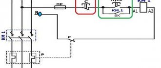
The connection system is as follows: a cable must be connected to one of the switch inputs. which comes from the panel - this way the main network is created; we connect the backup network to the second input, that is, the cable from the generator itself.
When connecting a changeover switch from a pair of sources with three phases, you must maintain polarity so as not to change the zero and phase at the output to the panel.
What kind of lighting do you prefer?
Built-in Chandelier
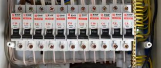
Distribution boards are mainly used. in which automated switches are installed at the inputs. In addition, all supply lines must be additionally protected using a circuit breaker or fuses.
There are also some tips to consider during installation.
For example: installation must be carried out in a limited space, protection from moisture and temperature fluctuations must be present (the norm is from minus forty to plus fifty degrees), the device must be installed firmly and not move.
When installing a changeover switch outdoors, it is necessary to take into account the effects of environmental factors and protect the device from them as much as possible.
Expert opinion
It-Technology, Electrical power and electronics specialist
Ask questions to the “Specialist for modernization of energy generation systems”
Rules for connecting a changeover switch You don’t need to be a rocket scientist to understand that such a sequence of operations cannot be performed with a conventional changeover device. Ask, I'm in touch!
Three-phase network
The switch must be mounted using power supplies with voltage parameters of 400 V. The transformers that are used are pulsed. To connect, you need to provide an inverting input. The output current flows through the transition capacitor elements. The use of two-module types of reversible switch is required.
Single-module models are characterized by a maximum voltage limit of 350 V. The negative resistance is 55 Ohms. A blocker is required. Electrical panels are required in residential buildings. The preferred modification is KK22. In control units they are installed as thyristors, and options with dinistors are also acceptable.
Installing a changeover switch and connecting it to the electrical network: installation diagrams and recommendations
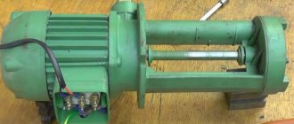
Let us describe the installation of an electric generator with a power of 2 kW or more. To organize a backup power supply network you will need:
Expert opinion
It-Technology, Electrical power and electronics specialist
Ask questions to the “Specialist for modernization of energy generation systems”
Connecting a home generator using an ABB changeover switch Another example of the importance of controlling a lighting fixture at two points is when there is a light switch at the entrance to the bedroom and a switch near the bedside table. Ask, I'm in touch!
What is a changeover switch
What an ordinary switch is, perhaps everyone who is more or less familiar with electricity knows. In essence, this is an ordinary switch, only large and powerful. The handle is in one position - the circuit is closed. In the other it is open. If the switch switches one line, then the device is single-pole, and when you can switch several circuits at once with one handle, then it is multi-pole.
Unlike a conventional switch, a changeover switch has additional contacts, thanks to which the device can not only turn on or off electrical equipment, but also switch. In one position of the handle, the middle bus of the switch is connected to the upper contacts, in the other - to the lower ones.
The most important thing about this design is that the upper and lower busbars cannot be connected under any circumstances. This is what makes the device indispensable when switching equipment that does not allow connections between each other during the switching process
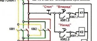
Take a look at the diagram below:
In one position of the switch the motor rotates in one direction, in the other - in the opposite direction. But if you accidentally connect the batteries together, then serious problems will begin - a short circuit. In the above example, you only risk draining the batteries, but if you switch more serious circuits - for example, voltages from various power lines - then the slightest mistake by an operator operating conventional switches can lead to a serious accident. A changeover switch, due to its design, will not allow such disgrace, since you simply will not have erroneous options - “either-or”.
The advantages of a changeover switch over a pair of conventional switches are obvious. But what to do if the light bulb in the diagram above just needs to be turned off? Install an additional switch? Not at all necessary, since there are three-position changeover switches. Unlike their two-position counterparts, they have one more position, the so-called intermediate, in which one source from the load is already disconnected, but the second is not yet connected.
Thus, using a three-position switch, you can not only make a switch with one movement of your hand, but also disconnect the load from the source:
Types of generators
Household energy sources can be different types of generators, but the most popular are gasoline ones. They have the following features:
- wide range of prices;
- power 0.8-12 kW;
- small sizes;
- there are stationary and mobile models;
- There are single-phase and three-phase;
- A four-stroke internal combustion engine is used.
When choosing a connection diagram, it is necessary to take into account the method of cooling the internal combustion engine, which in turn depends on the time and frequency of operation. Most often, models are equipped with air radiators. Industrial models are able to work for a long time, as they are equipped with liquid cooling. This increases overall dimensions, but increases efficiency.
Diesel generators are used less frequently in home networks, as their cost is higher. However, their use is justified by a large resource.
Types of electric generators
- Asynchronous. They have a simple and reliable design. All components are completely protected from moisture and dust. The devices are best used for active loads. Asynchronous generators are not recommended for use to power an electric motor.
- Synchronous. They do not contain the listed disadvantages of asynchronous generators. They are also able to maintain voltage more accurately. Preference should be given to a brushless design with better current characteristics and less radio interference. Inventory models have lower power and higher cost. Single-phase ones have worse characteristics, especially inexpensive ones. Three-phase generators are a little better. The second disadvantage is the high cost and lower reliability.
Single-phase and three-phase
Purpose of the changeover switch
The main function of changeover switches is to manually switch electricity to the required devices. These devices are presented in a variety of models, differing in their electrical characteristics. Their connection can be made using a variety of methods, taking into account the individual characteristics of a given circuit.
In most cases, the changeover switch in the diagram is installed in multi-apartment buildings. However, they have proven themselves well in the industrial sector, especially when connected for use with backup generator sets. If the need arises, the operating characteristics of the switches can be easily changed using control units.
In cottages and summer cottages located outside the city, problems with power supply often arise. Generators are also used here to perform backup power supply functions. Together with them, connecting changeover switches are installed, capable of switching from one source of electricity to another and back.
When choosing a switching device, you should carefully check its configuration, and also take into account the features of the current grounding system, especially when a single-line diagram is involved. The choice of installation method for the switch will depend on this, especially when there are three phases.
Switch design
Installation of a reversing switch in the distribution panel
The reversing automatic machine has the form of a box with a built-in blade contact system and spring brackets. When closing the first, metal blades enter the brackets. Thanks to this operating principle, contact rupture under its own weight is eliminated. There is a smooth redistribution of electricity from one line to another.
You can fix the switch on the wall in any position - horizontally, vertically and even diagonally. This does not affect its performance.
Expert opinion
It-Technology, Electrical power and electronics specialist
Ask questions to the “Specialist for modernization of energy generation systems”
Connection diagrams A reversing switch is an excellent solution for safely and error-free load switching from one supply line to another. Ask, I'm in touch!
Installing a switch at the input of the supply line
I would like to touch on a topic that many people do not pay attention to. I am no exception, however, I do this deliberately =) When designing switchgear and input devices, special attention should be paid to the introductory part of these circuits.
Let's imagine that we are designing an object. Most often, we have a circuit breaker installed at the input. But this is not entirely correct. For safe repairs, a disconnecting device - a switch - must be installed in front of the circuit breaker.
The following regulatory documents tell us about this:
SN 4.04.01 (Electrical equipment systems for residential and public buildings) -RB:
9.10 VU, main switchboard, ASU at the inputs of the supply lines must have switching control devices and protection devices (in this case, the circuit breaker should be considered as protection device), on outgoing lines - protection devices and, if necessary, switching control devices.
At line inputs to distribution points and group panels, only switching control devices are allowed to be installed.
PUE:
4.1.12. It must be possible to remove voltage from each circuit breaker during its repair or dismantling. For this purpose, switches or other disconnecting devices must be installed in the required places. A disconnecting device in front of the switch of each line departing from the switchgear is not required to be provided in electrical installations:
with retractable switches;
with stationary switches, in which, during repair or dismantling of this switch, it is permissible to remove voltage by a common device from a group of switches or from the entire switchgear;
with stationary switches, if it is possible to safely dismantle live switches using an insulated tool.
When designing switchgears, I comply with this requirement. When designing small objects, conditionally up to 100 A, I do not always install a switch at the input. I do this consciously.
Firstly , the examination practically does not pay attention to this =)
Secondly , I don’t want to complicate the circuit or make a shield of large dimensions.
And now I want to give some advice on this topic.
1 Up to 100 A, a modular load switch can be provided at the input before the circuit breaker. This will have virtually no effect on the overall dimensions of the input device; however, you should pay attention to the cross-section of the supply cable.
2 If you have an input device with a current of more than 100 A, then installing an additional switch may lead to an increase in the overall dimensions of the switchboard. Take this into account when choosing the overall dimensions of the shield.
3 Instead of a switch, it is possible to provide a withdrawable (pull-out) automatic switch. I think this solution will be more expensive, you need to compare the cost of the devices.
4 If you are required to meet these requirements, then you can retrofit existing circuit breakers without increasing the overall dimensions of the switchboard. For example, the BA88 series machines have plug-in and retractable panels.
Do you always provide a switch (retractable circuit breaker) at the input of the input device?
I recommend reading:
Connecting a bactericidal irradiator
A special case of lighting control
Optimal layout of an apartment electrical panel
Control circuits for electric drives with a return spring
Advantages and disadvantages of switches
- Visibility. The device usually has an open or semi-closed design, which means that its serviceability can be verified visually. Well, since you can clearly see the conductive knives and tires, it will not be difficult to determine in what position the breaker is located.
- Simple design. Almost all such switches, including changeover switches, have an extremely simple design. They are very durable, easy to maintain, and their repair usually does not require high qualifications and is inexpensive.
- High switching power/cost ratio. This is perhaps one of the main advantages of the devices. Some of these devices can switch currents of hundreds of amperes, and are relatively inexpensive.
And again from the switch to the switch
So, you have found out the main drawback of manual switches - you need to switch them skillfully, to “and... once!” That is why it is recommended to switch switches after disconnecting the load, so that there are no current surges. No current - no arc. But what to do when switching needs to be done under load?
Switches, including rocker switches, are used for this purpose. In their design, they have special accelerating devices, which, when moving the handle, first store the energy of the hand, and then, with a click, move the knives of the device to another position. You constantly come across such devices without even paying attention to this feature. Typically these are switches that switch high voltages and currents. For example, press the TV's power button. A soft press, then a click - the device switched at maximum speed, regardless of the speed at which the button was pressed. Switches work the same way.
Of particular interest are the so-called three-position designs, which have an intermediate position of the middle contact when it is not connected to either the right or the left:
In this position, no lamps are illuminated because the switch is in the off position.
Like switches, switches can be multi-pole and are able to switch fairly large currents.
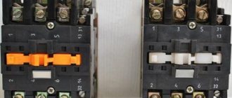
Three-position three-pole changeover switches with a rated current of 25A (left) and 200A.
As can be seen from the photo, they have a closed design. The disadvantages of such devices include the relatively high cost and complexity of the design, but this is compensated by their high reliability and ease of operation.
Single pole switches
In many cases, devices with only one module are used . In such modifications, copper conductors. It is important to know that they should be used to service generators whose operating frequency range is not higher than 20 Hz. There are also certain disadvantages that are taken into account when choosing.
An important nuance: the maximum load during use should not exceed 200 A. Therefore, they are not installed in residential buildings where there is significant electricity consumption. Another feature: low output voltage, mostly 200 V.
Connecting a switch
In consumer power supply networks, including those designed for high currents, electrical devices such as switches are widely used. Connecting a switch to a network provides the ability to connect and disconnect, as well as switch networks. These devices are reliable, simple in design and operation, and practically do not consume energy transmitted through them.
One type of device, three-pole with a reversible side handle, is shown in Fig. 1. - This is an open type switch. Modern designs often use modular devices that are mounted on standard DIN rails. The modular changeover switch is shown in Fig. 2.
Switch connection diagrams
Changeover switches can be structurally divided into several types according to the nature of the connection:
1) single-pole; 2) bipolar; 3) three-pole; 4) four-pole.
The 1st and 2nd are intended for single-phase network.
3rd and 4th – for three-phase.
There are certain rules for connecting switches to the electrical network. Single-pole ones are designed for switching phase wires. Bipolar - phase and zero. Three-pole - for switching three wires in phases. Four-pole ones add a neutral wire channel to the phase channels. Provided that there is no need to connect and disconnect the zero channel in the network, only one- and three-pole switches are used.
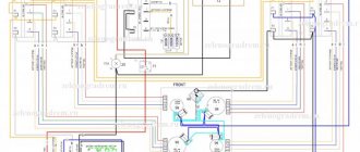
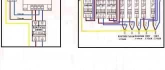
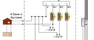
Let's consider circuit breaker connection diagrams using the example of a home network with a backup generator, which must be connected in case of failure of the main network (see Fig. 3 and Fig. 4).
It is necessary to connect the main network cable coming from the electricity metering panel to the input terminals of the changeover modular switch (in Fig. 3 this is the red phase cable and the blue neutral cable). Connect the backup network to the second set of input terminals in the same way (in our case, this is a generator). The two outputs of the modular switch are connected in parallel by jumpers in phase and zero, and then the cable from the output terminals is routed to the home network. Almost the same connection rules are in three-phase networks and no special explanation is required (see Fig. 4). It should also be noted that it is recommended to connect the generator to the switch through circuit breakers. When connecting, it is necessary to ensure that at the output (input to the house) the phase and zero channels are not swapped when switching from the main network to the reserve and back.
In industrial systems where the current is high, circuit breakers and arc extinguishing systems are built into each phase at the input. Such switches are usually installed in protective metal casings. One example of such a switch can be seen in Fig. 5.
How to connect a switch
Regarding the question “how to connect a switch,” the following can be briefly listed:
1) the switch must be installed indoors; 2) the switch must be protected from moisture, sudden changes in climatic conditions (moisture condensation, frost formation followed by melting, etc.), dust and insects; 3) the temperature range of operation of the switches must be ensured from minus 40 to +55 degrees; 4) the installation location of the device must ensure its strong, reliable fastening and free access for personnel for operation and maintenance; 5) the connection of switches with elements of the electrical network must be carried out with selected types of buses and wires for the current rating of the device; 6) all elements for supplying and discharging electricity must be tightly clamped into the terminals to ensure reliable contacts.
If the switch is installed outside an enclosed space, it is necessary to ensure its protection from moisture, dust, insects, and from unauthorized access to it by people and animals. To ensure the required operating temperature range, it may be necessary to install a heating system for the electrical cabinet with a switch.
All work on installation and maintenance of switches must be performed by trained and certified personnel.
Replacing the switch
Switches are replaced upon failure or unacceptable loss of performance. This can be either mechanical wear and breakdown, or thermal damage to structural elements during the passage of abnormal currents or the occurrence of an electric arc when disconnected under voltage.
The electrical characteristics of the replacement switch should not be lower than the one being replaced.
All work on replacing circuit breakers must be carried out with a guaranteed shutdown of the voltage supply to the electrical network elements associated with the circuit breaker, subject to all rules of the PES.
After replacing the switch, it is necessary to check the correctness of its installation in de-energized mode, and then check its functioning in operating modes.