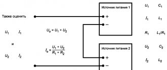
⇡#Linear and switching power supplies
Let's start with the basics. The power supply in a computer performs three functions. First, alternating current from the household power supply must be converted to direct current. The second task of the power supply is to reduce the voltage of 110-230 V, which is excessive for computer electronics, to the standard values required by power converters of individual PC components - 12 V, 5 V and 3.3 V (as well as negative voltages, which we will talk about a little later) . Finally, the power supply plays the role of a voltage stabilizer.
There are two main types of power supplies that perform the above functions - linear and switching. The simplest linear power supply is based on a transformer, on which the alternating current voltage is reduced to the required value, and then the current is rectified by a diode bridge.
However, the power supply is also required to stabilize the output voltage, which is caused by both voltage instability in the household network and a voltage drop in response to an increase in current in the load.
To compensate for the voltage drop, in a linear power supply the transformer parameters are calculated to provide excess power. Then, at high current, the required voltage will be observed in the load. However, the increased voltage that will occur without any means of compensation at low current in the payload is also unacceptable. Excess voltage is eliminated by including a non-useful load in the circuit. In the simplest case, this is a resistor or transistor connected through a Zener diode. In a more advanced version, the transistor is controlled by a microcircuit with a comparator. Be that as it may, excess power is simply dissipated as heat, which negatively affects the efficiency of the device.
An example of a linear power supply with a stabilizer. Excess power is dissipated in transistor Q1
In the switching power supply circuit, one more variable appears, on which the output voltage depends, in addition to the two already existing: input voltage and load resistance. There is a switch in series with the load (which in the case we are interested in is a transistor), controlled by a microcontroller in pulse width modulation (PWM) mode. The higher the duration of the open states of the transistor in relation to their period (this parameter is called duty cycle, in Russian terminology the inverse value is used - duty cycle), the higher the output voltage. Due to the presence of a switch, a switching power supply is also called Switched-Mode Power Supply (SMPS).
No current flows through a closed transistor, and the resistance of an open transistor is ideally negligible. In reality, an open transistor has resistance and dissipates some of the power as heat. In addition, the transition between transistor states is not perfectly discrete. And yet, the efficiency of a pulsed current source can exceed 90%, while the efficiency of a linear power supply with a stabilizer reaches 50% at best.
The simplest circuit of an AC/DC pulse converter with a transformer
Another advantage of switching power supplies is the radical reduction in the size and weight of the transformer compared to linear power supplies of the same power. It is known that the higher the frequency of alternating current in the primary winding of a transformer, the smaller the required core size and the number of winding turns. Therefore, the key transistor in the circuit is placed not after, but before the transformer and, in addition to voltage stabilization, is used to produce high-frequency alternating current (for computer power supplies this is from 30 to 100 kHz and higher, and as a rule - about 60 kHz). A transformer operating at a power supply frequency of 50-60 Hz would be tens of times more massive for the power required by a standard computer.
Linear power supplies today are used mainly in the case of low-power applications, where the relatively complex electronics required for a switching power supply constitute a more sensitive cost item compared to a transformer. These are, for example, 9 V power supplies, which are used for guitar effects pedals, and once for game consoles, etc. But chargers for smartphones are already entirely pulsed - here the costs are justified. Due to the significantly lower amplitude of voltage ripple at the output, linear power supplies are also used in those areas where this quality is in demand.
Parameters and characteristics
The power supply unit of a personal computer has many parameters that may not be indicated in the documentation. Several parameters are indicated on the side label - voltage and power.
Power is the main indicator
This information is written on the label in large print. The power rating of a power supply indicates the total amount of electricity available to internal components.
It would seem that choosing a power supply with the required power would be enough to sum up the consumed indicators of the components and select a power supply with a small margin. Therefore, there will not be a big difference between 200w and 250w.
But in reality the situation looks more complicated, because the output voltage can be different - +12V, -12V and others. Each voltage line consumes a certain amount of power. But in the power supply there is one transformer that generates all the voltages used by the PC. In rare cases, two transformers may be placed. This is an expensive option and is used as a source on servers.
In simple power supplies, 1 transformer is used. Because of this, the power on the voltage lines can change, increase with low load on other lines, and vice versa decrease.
Operating voltage
When choosing a power supply, you should pay attention to the maximum operating voltage values, as well as the range of incoming voltages; it should be from 110V to 220V.
True, most users do not pay attention to this and when choosing a power supply with ratings from 220V to 240V they risk frequent PC shutdowns.
Such a power supply will turn off when the voltage drops, which is not uncommon for our electrical networks. Exceeding the declared values will lead to the PC turning off and the protection will work. To turn the power supply back on, you will have to disconnect it from the network and wait a minute.
It should be remembered that the processor and video card consume a maximum operating voltage of 12V. Therefore, you should pay attention to these indicators. To reduce the load on the connectors, the 12V line is divided into a parallel pair with the designation +12V1 and +12V2. These indicators must be indicated on the label.
⇡#General diagram of an ATX power supply
A desktop computer's power supply is a switching power supply, the input of which is supplied with household voltage with parameters of 110/230 V, 50-60 Hz, and the output has a number of DC lines, the main ones of which are rated 12, 5 and 3.3 V In addition, the power supply provides a voltage of -12 V, and sometime also a voltage of -5 V, necessary for the ISA bus. But the latter was at some point excluded from the ATX standard due to the end of support for the ISA itself.
Block diagram of a pulse power supply
In the simplified diagram of a standard switching power supply presented above, four main stages can be distinguished. In the same order, we consider the components of power supplies in the reviews, namely:
- EMI filter – electromagnetic interference (RFI filter);
- primary circuit - input rectifier, key transistors (switcher), creating high-frequency alternating current on the primary winding of the transformer;
- main transformer;
- secondary circuit - current rectifiers from the secondary winding of the transformer (rectifiers), smoothing filters at the output (filtering).
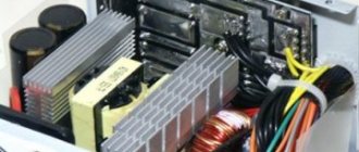
Internal structure of the power supply unit (AeroCool KCAS-650M)
Complete circuit diagram of a simple ATX power supply
Checking voltage after repair
After repair, you need to check the presence of output voltages. To do this, you need to install a jumper between the black and green conductors on the ATX connector and connect load equivalents to the output connectors - without them, the output voltages may be higher than the rated ones. It is better to do this before applying mains voltage, because some circuits simply will not start without a load.
You can use resistors or 12-volt automotive incandescent lamps as ballast. The load must provide an output current within 10..90% of the nominal.
For clarity, we recommend a series of thematic videos.
Repairing a computer power supply is not difficult if you have the equipment and sufficient qualifications. But repairing a computer's power supply with your own hands is considered impractical, since troubleshooting takes a lot of time. There is an opinion that it is easier to buy a new unit, because by the time the power supply fails, the computer is either upgraded or requires an upgrade in the near future. Therefore, a new power supply with increased power is needed. There is a fair amount of truth in this approach, but sometimes repairs are required. Also, a refurbished power supply can be converted into a laboratory power supply or a charger. The review materials will be useful in this case.
⇡#EMF filter
The filter at the power supply input is used to suppress two types of electromagnetic interference: differential (differential-mode) – when the interference current flows in different directions in the power lines, and common-mode (common-mode) – when the current flows in one direction.
Differential noise is suppressed by capacitor CX (the large yellow film capacitor in the photo above) connected in parallel with the load. Sometimes a choke is additionally attached to each wire, which performs the same function (not on the diagram).
The common mode filter is formed by CY capacitors (blue drop-shaped ceramic capacitors in the photo), connecting the power lines to ground at a common point, etc. a common-mode choke (LF1 in the diagram), the current in the two windings of which flows in the same direction, which creates resistance for common-mode interference.
EMI filter circuit
In cheap models, a minimum set of filter parts is installed; in more expensive ones, the described circuits form repeating (in whole or in part) links. In the past, it was not uncommon to see power supplies without any EMI filter at all. Now this is rather a curious exception, although if you buy a very cheap power supply, you can still run into such a surprise. As a result, not only and not so much the computer itself will suffer, but other equipment connected to the household network - switching power supplies are a powerful source of interference.
In the filter area of a good power supply, you can find several parts that protect the device itself or its owner from damage. There is almost always a simple fuse for short circuit protection (F1 in the diagram). Note that when the fuse trips, the protected object is no longer the power supply. If a short circuit occurs, it means that the key transistors have already broken through, and it is important to at least prevent the electrical wiring from catching fire. If a fuse in the power supply suddenly burns out, then replacing it with a new one is most likely pointless.
Separately, protection against short-term voltage surges is provided using a varistor (MOV - Metal Oxide Varistor). But there are no means of protection against prolonged voltage increases in computer power supplies. This function is performed by external stabilizers with their own transformer inside.
EMI filter (Antec VP700P)
The capacitor in the PFC circuit after the rectifier can retain a significant charge after being disconnected from power. To prevent a careless person who sticks his finger into the power connector from receiving an electric shock, a high-value discharge resistor (bleeder resistor) is installed between the wires. In a more sophisticated version - together with a control circuit that prevents charge from leaking when the device is operating.
By the way, the presence of a filter in the PC power supply (and the power supply of a monitor and almost any computer equipment also has one) means that buying a separate “surge filter” instead of a regular extension cord is, in general, pointless. Everything is the same inside him. The only condition in any case is normal three-pin wiring with grounding. Otherwise, the CY capacitors connected to ground simply will not be able to perform their function.
ATX computer power supply repair
Attention! To avoid damaging the computer, uncoupling and connecting the connectors of the power supply and other components inside the system unit must be performed only after completely disconnecting the computer from the power supply.
(remove the plug from the socket or turn off the switch in the “Pilot”).
The first thing that needs to be done is to check the presence of voltage in the outlet and the serviceability of the “Pilot” type extension cord by the glow of its switch key. Next, you need to check that the computer’s power cord is securely inserted into the “Pilot” and the system unit and that the switch (if any) on the back wall of the system unit is turned on.
How to find a power supply fault by pressing the “Start” button
If power is supplied to the computer, then in the next step you need to look at the power supply cooler (visible behind the grille on the back wall of the system unit) and press the “Start” button of the computer. If the cooler blades move even a little, it means that the filter, fuse, diode bridge and capacitors on the left side of the block diagram are working, as well as the independent low-power power supply +5 B_SB.
In some PSU models, the cooler is on the flat side and to see it, you need to remove the left side wall of the system unit.
Turning at a small angle and stopping the cooler impeller when you press the “Start” button indicates that output voltages momentarily appear at the output of the power supply unit, after which the protection is triggered, stopping the operation of the power supply unit. The protection is configured in such a way that if the current value for one of the output voltages exceeds a specified threshold, then all voltages are turned off.
The cause of an overload is usually a short circuit in the low-voltage circuits of the power supply itself or in one of the computer units. A short circuit usually occurs when there is a breakdown in semiconductor devices or insulation in capacitors.
To determine the node in which a short circuit has occurred, you need to disconnect all power supply connectors from the computer units, leaving only those connected to the motherboard. Then connect the computer to the power supply and press the “Start” button. If the cooler in the power supply was spinning, it means that one of the disconnected nodes is faulty. To determine the faulty node, you need to connect them in series to the power supply.
If the power supply connected only to the motherboard does not work, you should continue troubleshooting and determine which of these devices is faulty.
Checking the computer power supply by measuring the resistance value of the output circuits
When repairing a power supply, some types of its malfunction can be determined by measuring with an ohmmeter the resistance value between the common black GND wire and the remaining contacts of the output connectors.
Before starting measurements, the power supply must be disconnected from the power supply, and all its connectors must be disconnected from the system unit components. The multimeter or tester must be turned on in resistance measurement mode and select a limit of 200 Ohms. Connect the common wire of the device to the connector contact to which the black wire goes. The end of the second probe touches the contacts in turn, in accordance with the table.
| Table of resistance between the terminals of the ATX power supply | ||||||
| Output voltage, V | +3,3 | +5,0 | +12,0 | -12,0 | +5.0 SB | GND |
| Wire color | orange | red | yellow | blue | violet | black |
| Resistance should be more than ohm | 6,5 | 20 | 130 | 98 | 46 | — |
| Most probable values, Ohm | 7, 15, 32, ∞ | 50, 96, 200, ∞ | 136, 264, ∞ | 98,195, ∞ | 46, 98, ∞ | — |
The table shows generalized data obtained as a result of measuring the resistance value of the output circuits of 20 serviceable power supply units of computers of different capacities, manufacturers and years of manufacture.
To be able to connect a power supply for testing without load, load resistors are installed inside the unit at some outputs, the value of which depends on the power of the power supply and the manufacturer’s decision. Therefore, the measured resistance can fluctuate over a wide range, but should not be below the permissible value.
If a load resistor is not installed in the circuit, then the ohmmeter readings will vary from a small value to infinity. This is due to the charging of the filter electrolytic capacitor from the ohmmeter and indicates that the capacitor is working. If you swap the probes, a similar picture will be observed. If the resistance is high and does not change, then the capacitor may be broken.
A resistance less than the permissible value indicates the presence of a short circuit, which may be caused by an insulation breakdown in an electrolytic capacitor or a rectifying diode. To determine the faulty part, you will have to open the power supply and unsolder one end of the filter choke of this circuit from the circuit. Next, check the resistance before and after the throttle. If after it, then there is a short circuit in the capacitor, wires, between the tracks of the printed circuit board, and if before it, then the rectifier diode is broken.
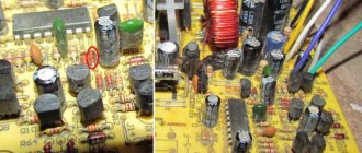
Troubleshooting the power supply by external inspection
Initially, you should carefully inspect all the parts, paying special attention to the integrity of the geometry of the electrolytic capacitors. As a rule, due to severe temperature conditions, electrolytic capacitors fail most often. About 50% of power supply failures are due to faulty capacitors. Often, swelling of capacitors is a consequence of poor performance of the cooler. The cooler bearings run out of lubrication and the speed drops. The cooling efficiency of the power supply parts decreases and they overheat. Therefore, at the first sign of a malfunction of the power supply cooler, additional acoustic noise usually appears; you need to clean the cooler from dust and lubricate it.
If the capacitor body is swollen or traces of leaked electrolyte are visible, then the failure of the capacitor is obvious and it should be replaced with a serviceable one. The capacitor swells in the event of an insulation breakdown. But it happens that there are no external signs of failure, but the level of output voltage ripple is greater. In such cases, the capacitor is faulty due to lack of contact between its terminal and the plate inside it, as they say, the capacitor is broken. You can check the capacitor for open circuit using any tester in resistance measurement mode. The technology for testing capacitors is presented in the website article “Measuring Resistance”.
Next, the remaining elements, fuse, resistors and semiconductor devices are inspected. Inside the fuse, a thin metal wire should run along the center, sometimes with a thickening in the middle. If the wire is not visible, then most likely it has burned out. To accurately check the fuse, you need to test it with an ohmmeter. If the fuse is blown, it must be replaced with a new one or repaired. Before making a replacement, to check the power supply, you can not solder the blown fuse from the board, but solder a copper wire with a diameter of 0.18 mm to its terminals. If the wiring does not burn out when you turn on the power supply to the network, then it makes sense to replace the fuse with a working one.
How to check the serviceability of the power supply by closing the PG and GND contacts
If the motherboard can only be checked by connecting it to a known-good power supply, then the power supply can be checked separately using a load block or started by connecting the +5 V PG and GND contacts to each other.
From the power supply to the motherboard, supply voltages are supplied using a 20 or 24 pin connector and a 4 or 6 pin connector. For reliability, the connectors have latches. In order to remove the connectors from the motherboard, you need to press the latch upward with your finger at the same time, applying quite a lot of force, rocking from side to side, and pull out the mating part.
Next, you need to short-circuit the two terminals in the connector removed from the motherboard with each other, using a piece of wire or perhaps a metal paper clip. The wires are located on the latch side. In the photographs, the location of the jumper is indicated in yellow.
If the connector has 20 pins
, then you need to connect pin
14
(green wire, in some power supplies it may be gray, POWER ON) and pin
15
(black wire, GND).
If the connector has 24 pins
, then you need to connect pin
16
(green, in some power supplies the wire may be gray, POWER ON) and pin
17
(black GND wire).
If the impeller in the power supply cooler rotates, then the ATX power supply can be considered operational, and, therefore, the reason for the computer not working is in other units. But such a check does not guarantee stable operation of the computer as a whole, since deviations in output voltages may be greater than permissible.
Checking the computer's power supply by measuring voltages and ripple levels
After repairing the power supply or in case of unstable operation of the computer, in order to be completely sure that the power supply is in good working order, it is necessary to connect it to the load block and measure the level of output voltages and the ripple range. The deviation of voltage values and ripple amplitude at the output of the power supply should not exceed the values given in the table.
You can do without a load block by measuring the voltage and ripple level directly at the terminals of the power supply connectors in a running computer.
| Table of output voltages and ripple range of ATX power supply | |||||||
| Output voltage, V | +3,3 | +5,0 | +12,0 | -12,0 | +5.0 SB | +5.0 PG | GND |
| Wire color | orange | red | yellow | blue | violet | grey | black |
| Permissible deviation, % | ±5 | ±5 | ±5 | ±10 | ±5 | – | – |
| Permissible minimum voltage | +3,14 | +4,75 | +11,40 | -10,80 | +4,75 | +3,00 | – |
| Permissible maximum voltage | +3,46 | +5,25 | +12,60 | -13,20 | +5,25 | +6,00 | – |
| Ripple range no more than, mV | 50 | 50 | 120 | 120 | 120 | 120 | – |
When measuring voltages with a multimeter, the “negative” end of the probe is connected to the black wire (common), and the “positive” end to the desired connector contacts.
Voltage +5 V SB (Stand-by), purple wire – produces an independent low-power power supply built into the power supply unit, made on one field-effect transistor and transformer. This voltage ensures the computer operates in standby mode and serves only to start the power supply. When the computer is running, the presence or absence of +5 V SB voltage does not matter. Thanks to +5 V SB, the computer can be started by pressing the “Start” button on the system unit or remotely, for example, from an uninterruptible power supply unit in the event of a prolonged absence of 220 V supply voltage.
Voltage +5 V PG (Power Good) - appears on the gray wire of the power supply unit after 0.1-0.5 seconds if it is in good condition after self-testing and serves as an enabling signal for the operation of the motherboard.
A voltage of minus 12 V (blue wire) is only needed to power the RS-232 interface, which is absent in modern computers. Therefore, power supplies of the latest models may not have this voltage.
How to replace a fuse in a computer's power supply
Typically, computer power supplies are equipped with a tubular glass fuse designed for a protection current of 6.3 A. For reliability and compactness, the fuse is soldered directly into the printed circuit board. For this purpose, special fuses are used that have terminals for sealing. The fuse is usually installed in a horizontal position next to the surge protector and is easy to spot by its appearance.
But sometimes there are power supplies in which the fuse is installed in a vertical position and a heat-shrinkable tube is put on it, as in the photo above. As a result, it is difficult to detect. But the inscription on the printed circuit board next to the fuse helps: F1 - this is how the fuse is designated on electrical circuits. Next to the fuse, the current for which it is rated may also be indicated; on the presented board, a current of 6.3 A is indicated.
When repairing the power supply and checking the vertically installed fuse using a multimeter, it was discovered that it was broken. After desoldering the fuse and removing the heat shrink tubing, it became obvious that it had blown. The inside of the glass tube was completely covered with a black coating from the burnt wire.
Fuses with wire leads are rare, but they can be successfully replaced with ordinary 6.3 ampere fuses by soldering single-core pieces of copper wire with a diameter of 0.5-0.7 mm to the ends of the cups.
All that remains is to solder the prepared fuse into the printed circuit board of the power supply and check its functionality.
If, when the power supply is turned on, the fuse burns out again, it means that there is a failure of other radio elements, usually a breakdown of the transitions in the key transistors. Repairing a power supply with such a fault requires high qualifications and is not economically feasible. Replacing a fuse designed for a higher protection current than 6.3 A will not lead to a positive result. The fuse will still blow.
Searching for faulty electrolytic capacitors in the power supply
Very often, a power supply failure, and as a result, unstable operation of the computer as a whole, occurs due to swelling of the electrolytic capacitor housings. To protect against explosion, notches are made at the end of electrolytic capacitors. As the pressure inside the capacitor increases, the housing swells or ruptures at the notch, and by this sign it is easy to find a failed capacitor. The main reason for the failure of capacitors is their overheating due to a malfunction of the cooler or exceeding the permissible voltage.
The photo shows that the capacitor on the left side has a flat end, while the end on the right is swollen, with traces of leaking electrolyte. This capacitor has failed and must be replaced. In the power supply, electrolytic capacitors on the +5 V power bus usually fail, since they are installed with a small voltage margin, only 6.3 V. I have encountered cases when all the capacitors in the power supply on the +5 V circuit were swollen.
When replacing capacitors on a 5 V power supply circuit, I recommend installing capacitors that are designed for a voltage of at least 10 V. The higher the voltage the capacitor is designed for, the better, the main thing is that the dimensions fit into the installation location. If a capacitor with a higher voltage does not fit due to its size, you can install a capacitor with a smaller capacity, but designed for a higher voltage. All the same, the capacity of the capacitors installed at the factory has a large reserve and such a replacement will not worsen the performance of the power supply and the computer as a whole.
The larger the capacity of the installed capacitor, the better. So when replacing, it is better to choose a capacitor designed for a higher voltage and capacity than that of the failed one. Replacing a failed capacitor in a power supply is not difficult if you have the skills to work with a soldering iron. The article on the website “How to solder with a soldering iron” is devoted to soldering techniques.
There is no point in replacing electrolytic capacitors in the power supply if they are all swollen. This means that the output voltage stabilization circuit has failed, and a voltage exceeding the permissible value was applied to the capacitors. Such a power supply can be repaired only with professional education and measuring instruments, but such repairs are not economically feasible.
The main thing when repairing a power supply is not to forget that electrolytic capacitors have polarity. On the negative terminal side of the capacitor body there is a marking in the form of a wide light vertical stripe, as shown in the photo above. On the printed circuit board, the hole for the negative terminal of the capacitor is located in the marking area of the white (black) semicircle, or the hole for the positive terminal is indicated by a “+” sign.
Checking the group stabilization choke BP ATX
If you suddenly smell something burning from the computer system unit, then one of the reasons may be overheating of the group stabilization choke in the power supply unit or a burnt winding of one of the coolers. The computer usually continues to work normally. If, after opening the system unit and inspecting it, all coolers rotate, then the throttle is faulty. The computer must be turned off immediately and repaired.
The photo shows a computer power supply with the cover removed, in the center of which you can see the inductor, covered with green insulation, burnt on top. When I connected this power supply to the load and applied supply voltage to it, after a couple of minutes a thin stream of smoke came out of the inductor. The check showed that all output voltages within the tolerance and the ripple range do not exceed the permissible value.
The current of all voltages supplying the computer passes through the inductor and it is obvious that there has been a violation of the insulation of the wires of the windings as a result of which they short-circuited among themselves.
The windings can be rewinded onto the same core, but as a result of strong heating, the magnetodielectric of the core may lose its quality factor; as a result, due to high Foucault currents, it will heat up even with intact windings. Therefore, I recommend installing a new throttle. If there is no analogue, then you need to count the turns of the windings, winding them on the burnt inductor, and wind them with an insulated wire of the same cross-section on a new core. In this case, the direction of the windings must be observed.
Checking other power supply elements
Resistors and simple capacitors should not have any darkening or deposits. The cases of semiconductor devices must be intact, without chips or cracks. When making repairs yourself, it is advisable to replace only the elements shown in the block diagram. If the paint on the resistor has darkened, or the transistor has fallen apart, then there is no point in changing them, since most likely this is a consequence of the failure of other elements that cannot be detected without instruments. A darkened resistor body does not always indicate a malfunction. It is quite possible that only the paint has darkened, but the resistance of the resistor is normal.
⇡#Active PFC block
In an AC circuit with a linear load (such as an incandescent light bulb or an electric stove), the current flow follows the same sine wave as the voltage. But this is not the case with devices that have an input rectifier, such as switching power supplies. The power supply passes current in short pulses, approximately coinciding in time with the peaks of the voltage sine wave (that is, the maximum instantaneous voltage) when the smoothing capacitor of the rectifier is recharged.
Current consumption of a switching power supply
The distorted current signal is decomposed into several harmonic oscillations in the sum of a sinusoid of a given amplitude (the ideal signal that would occur with a linear load).
The power used to perform useful work (which, in fact, is heating the PC components) is indicated in the characteristics of the power supply and is called active. The remaining power generated by harmonic oscillations of the current is called reactive. It does not produce useful work, but heats the wires and creates a load on transformers and other power equipment.
The vector sum of reactive and active power is called apparent power. And the ratio of active power to total power is called power factor - not to be confused with efficiency!
A switching power supply initially has a rather low power factor - about 0.7. For a private consumer, reactive power is not a problem (fortunately, it is not taken into account by electricity meters), unless he uses a UPS. The uninterruptible power supply is responsible for the full power of the load. At the scale of an office or city network, excess reactive power created by switching power supplies already significantly reduces the quality of power supply and causes costs, so it is being actively combated.
Electrical diagram and current consumption of the Active PFC unit
In particular, the vast majority of computer power supplies are equipped with active power factor correction (Active PFC) circuits. A unit with an active PFC is easily identified by a single large capacitor and inductor installed after the rectifier. In essence, Active PFC is another pulse converter that maintains a constant charge on the capacitor with a voltage of about 400 V. In this case, current from the supply network is consumed in short pulses, the width of which is selected so that the signal is approximated by a sine wave - which is required to simulate a linear load . To synchronize the current consumption signal with the voltage sinusoid, the PFC controller has special logic.
The active PFC circuit contains one or two key transistors and a powerful diode, which are placed on the same heatsink with the key transistors of the main power supply converter. As a rule, the PWM controller of the main converter key and the Active PFC key are one chip (PWM/PFC Combo).
Active PFC block and input rectifier (Antec VP700P)
The power factor of switching power supplies with active PFC reaches 0.95 and higher. In addition, they have one additional advantage - they do not require a 110/230 V mains switch and a corresponding voltage doubler inside the power supply. Most PFC circuits handle voltages from 85 to 265 V. In addition, the sensitivity of the power supply to short-term voltage dips is reduced.
By the way, in addition to active PFC correction, there is also a passive one, which involves installing a high-inductance inductor in series with the load. Its efficiency is low, and you are unlikely to find this in a modern power supply.
⇡#Main converter
The general principle of operation for all pulse power supplies of an isolated topology (with a transformer) is the same: a key transistor (or transistors) creates alternating current on the primary winding of the transformer, and the PWM controller controls the duty cycle of their switching. Specific circuits, however, differ both in the number of key transistors and other elements, and in qualitative characteristics: efficiency, signal shape, noise, etc. But here too much depends on the specific implementation for this to be worth focusing on. For those interested, we provide a set of diagrams and a table that will allow you to identify them in specific devices based on the composition of the parts.
| Transistors | Diodes | Capacitors | Transformer primary legs | |
| Single-Transistor Forward | 1 | 1 | 1 | 4 |
| Two-Transistor Forward | 2 | 2 | 0 | 2 |
| Half Bridge | 2 | 0 | 2 | 2 |
| Full Bridge | 4 | 0 | 0 | 2 |
| Push-Pull | 2 | 0 | 0 | 3 |
In addition to the listed topologies, in expensive power supplies there are resonant versions of Half Bridge, which are easily identified by an additional large inductor (or two) and a capacitor forming an oscillatory circuit.
| Single-Transistor Forward | Two-Transistor Forward | Push-Pull |
| Full Bridge | Half Bridge | Resonant Half-Bridge |
⇡#Secondary circuit
The secondary circuit is everything that comes after the secondary winding of the transformer. In most modern power supplies, the transformer has two windings: 12 V is removed from one of them, and 5 V from the other. The current is first rectified using an assembly of two Schottky diodes - one or several per bus (on the highest loaded bus - 12 V - in powerful power supplies there are four assemblies). More efficient in terms of efficiency are synchronous rectifiers, which use field-effect transistors instead of diodes. But this is the prerogative of truly advanced and expensive power supplies that claim the 80 PLUS Platinum certificate.
The 3.3V rail is typically driven from the same winding as the 5V rail, only the voltage is stepped down using a saturable inductor (Mag Amp). A special winding on a transformer for a voltage of 3.3 V is an exotic option. Of the negative voltages in the current ATX standard, only -12 V remains, which is removed from the secondary winding under the 12 V bus through separate low-current diodes.
PWM control of the converter key changes the voltage on the primary winding of the transformer, and therefore on all secondary windings at once. At the same time, the computer's current consumption is by no means evenly distributed between the power supply buses. In modern hardware, the most loaded bus is 12-V.
To separately stabilize voltages on different buses, additional measures are required. The classic method involves using a group stabilization choke. Three main buses are passed through its windings, and as a result, if the current increases on one bus, the voltage drops on the others. Let's say the current on the 12 V bus has increased, and in order to prevent a voltage drop, the PWM controller has reduced the duty cycle of the key transistors. As a result, the voltage on the 5 V bus could go beyond the permissible limits, but was suppressed by the group stabilization choke.
The voltage on the 3.3 V bus is additionally regulated by another saturable inductor.
Stabilizing chokes and output filter (Antec VP700P)
A more advanced version provides separate stabilization of the 5 and 12 V buses due to saturable chokes, but now this design has given way to DC-DC converters in expensive high-quality power supplies. In the latter case, the transformer has a single secondary winding with a voltage of 12 V, and the voltages of 5 V and 3.3 V are obtained thanks to DC-DC converters. This method is most favorable for voltage stability.
DC-DC converter for 5 V bus (CoolerMaster G650M)
Output filter
The final stage on each bus is a filter that smoothes out voltage ripple caused by the key transistors. In addition, the pulsations of the input rectifier, whose frequency is equal to twice the frequency of the supply network, penetrate to one degree or another into the secondary circuit of the power supply.
The ripple filter includes a choke and large capacitors. High-quality power supplies are characterized by a capacitance of at least 2,000 uF, but manufacturers of cheap models have reserves for savings when they install capacitors, for example, of half the nominal value, which inevitably affects the ripple amplitude.
Other problems
Another cause of power supply malfunction may be a malfunction of powerful transistors in the inverter switches. If pulses arrive at the bases (gates) of the triodes, but there are none in the collector (drain) circuit, the transistors must be unsoldered and ringed. Bipolar triodes are connected like two diodes with a common terminal.
We recommend reading: How to measure resistance with a multimeter: instructions, photos, videos
Testing bipolar triodes.
To test MOSFETs, it is better to assemble a simple circuit.
Field-effect transistor testing circuit.
You also need to check for the presence of the Power_good signal on pin 8 of the motherboard connector. It may turn out that all the voltages are in order, but the circuit for generating this signal is faulty. The computer will perceive this as a fault in the power supply.
⇡#Standby power supply +5VSB
A description of the components of the power supply would be incomplete without mentioning the 5 V standby voltage source, which makes the PC sleep mode possible and ensures the operation of all devices that must be turned on at all times. The “duty room” is powered by a separate pulse converter with a low-power transformer. In some power supplies, there is also a third transformer, which is used in the feedback circuit to isolate the PWM controller from the primary circuit of the main converter. In other cases, this function is performed by optocouplers (an LED and a phototransistor in one package).
Transformers (Corsair HX750i)
Tips for choosing a source
Before choosing a power supply for purchase, you should pay attention to the power consumption of the internal components of the PC.
But some video cards require a special current consumption of +12V and these indicators should be taken into account when choosing a power supply. Typically, for a PC with one video card installed, a source with a power of 500 W or 600 is sufficient.
You should also read customer reviews and expert reviews about the selected model and the manufacturer. The best parameters to pay attention to are: power, quiet operation, quality and compliance with the written characteristics on the label.
There is no need to save money, because the operation of the entire PC will depend on the operation of the power supply. Therefore, the better and more reliable the source, the longer the computer will last. The user can be sure that he has made the right choice and does not worry about sudden shutdowns of his PC.