Quite high parameters are declared, and the cost of the finished module is less than the cost of the parts included in it. The small size of the board is attractive. I decided to purchase a few and test them out. I hope my experience will be useful to less experienced radio amateurs.
↑ It’s hard to call it a stabilizer...
You might think that it is enough to take a transformer, a diode bridge, connect a module to them, and we have a stabilizer with an output voltage of 3...30 V and a current of up to 2 A (short-term up to 3 A).
That's exactly what I did. Without load everything was fine. A transformer with two windings of 18 V and a promised current of up to 1.5 A (the wire was clearly too thin by eye, and so it turned out). I needed a +-18 V stabilizer and I set the required voltage.
With a 12 Ohm load the current is 1.5 A, here is the waveform, 5 V/cell vertical.
It can hardly be called a stabilizer.
The reason is simple and clear: the capacitor on the board is 200 uF, it serves only for the normal operation of the DC-DC converter. When voltage was applied to the input from a laboratory power supply, everything was fine. The solution is obvious: you need to power the stabilizer from a source with low ripples, i.e. add a capacitance after the bridge.
DIY two-channel laboratory power supply
In amateur radio practice, it is impossible to get by with one standard power supply with a fixed voltage, since electronic circuits must be powered from different voltages. A good laboratory power supply should also have an indication of the set voltage and adjustable current protection, so that in case of any problems it does not damage the connected structure and does not burn out itself.
Such a universal power supply can be purchased, but it is more interesting, and sometimes even more profitable, to assemble it yourself. Moreover, now you can seriously save development time by using the universal voltage converter PW841 as a basis (see Fig. 1.).
An ideal solution for implementing a laboratory power supply, the PW841 allows you to:
— set the required output voltage in the range 1...30V;
— adjust the maximum current consumption from 0 to 5A;
— display voltage and current consumption simultaneously on two four-digit indicators;
- protect against excess output current and short circuit in the load.
Fig.1. Module Master Kit PW841
As an input voltage source for PW841, you can use a ready-made power adapter from household appliances. It is convenient to use a network adapter from a laptop: as a rule, they have an output voltage of 19V and a load current of 3A or more. It is impossible to obtain a voltage higher than the input value at the output of the finished design, but for most tasks this voltage will be quite sufficient. To maintain the ability to use the laptop adapter for its intended purpose, you need to select a power socket that matches its connector.
But you don’t have to look for easy ways and assemble the power part of the power supply yourself. The diagram of the simplest linear power supply is shown in Fig. 2.
Fig.2. The simplest transformer power supply
The circuit contains a transformer, a diode bridge and a capacitor. The transformer reduces the high mains voltage of 220V to the required safe level. The transformer can be purchased or found in old equipment (TVs, amplifiers, etc.). But keep in mind that most modern electronic designs use pulse transformers, and classic transformers are suitable for assembling a linear power supply: they are usually large and heavy.
I managed to find a transformer of the TTP series (toroidal transformer). There are a lot of transformers of different types in this series, differing in output voltage, power and number of output windings. In my case, the transformer has one 220V primary winding (black wires) and two identical secondary windings (red and white wire leads). Each of the independent outputs produces an alternating voltage of 15V with a maximum load current of up to 2A.
Since I was lucky to get a transformer with two secondary windings, I decided to assemble a two-channel laboratory power supply based on two PW841 modules. In some cases, an electronic circuit requires two different voltages to operate: for example, 5V and 12V; and for setting up such circuits it is much more convenient to use a two-channel power supply.
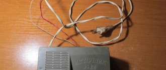
The transformer produces alternating voltage, so you will need to supplement the circuit with a diode rectifier. It is more convenient to use an assembly of four diodes in one housing, which can be purchased or removed from a faulty power supply. I used RS405 type diode bridges, which are designed for a current of up to 4A, but in my case more is not needed. It is also necessary to include filter capacitors in the circuit, which will remove voltage ripple after rectifying the alternating current. Capacitors with a capacity of several thousand microfarads are suitable. In Fig.3. showing the components I used to build the power supply.
Fig.3. Components for assembling a transformer power supply
When choosing a transformer and calculating circuit elements, you need to understand that after rectification, the DC voltage becomes approximately 1.4 times higher than the AC voltage. In my case, from 15V alternating voltage at the output of the rectifier it turned out to be 15x1.4 = 21V direct voltage. The operating voltage of the capacitor must be selected with some margin, that is, in this case, at least 25V. I found capacitors with a capacity of 6800 uF and an operating voltage of 50V.
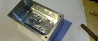
All that remains is to mount the entire structure in a housing of suitable dimensions. It is advisable to choose a looser housing so that the transformer and electronic components are better cooled. For the same purpose, it is recommended to drill ventilation holes in the housing if they were not originally provided for by the design.
Fig.4. Mounting the power supply in the case
I pulled the transformer with plastic ties to the bottom of the case. I secured the filter capacitors with hot glue from a glue gun, and soldered the diode bridges directly to the terminals of the capacitors using a hinged mounting. Resistors with a resistance of 6.8 MOhm are soldered parallel to the terminals of the capacitors: these are optional components, they serve to discharge the capacitors more quickly after disconnecting the power supply from the network.
To install the PW841 modules, I had to modify them: I removed the unused white connectors from the front part next to the displays and trimming resistors for adjusting the current and voltage; I replaced them with variable resistors of the appropriate value (50 kOhm).
I mounted most of the components of the power supply on the front plastic panel of the case (see Fig. 5.).
Fig.5. Front panel installation
In the front panel, I drilled four holes with a diameter of 7 mm for variable resistors, cut out two rectangular holes for the PW841 indicators, and glued the modules themselves to the front panel with a glue gun. As output power terminals I used an audio output block soldered from a broken music center. We also had to cut out a window for it. I installed a power switch on the side wall.
I connected the new variable resistors and power terminals to the corresponding PW841 mounting points with wires. To minimize current losses, it is advisable to use flexible conductors of minimal length and a cross-section of at least 1.5 mm2.
Rice. 6. Resistor, switch, power connector
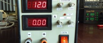
In Fig.7. The operation of the assembled power supply is demonstrated. On the left channel the voltage is set to 5.03V, the current consumption is 90 mA, a resistor with a total resistance of 50 Ohms is used as a load. The left channel in this example operates in the classic power supply mode, but if the load current exceeds the set threshold, the unit will switch to current-limiting mode, and the corresponding LED on the PW841 board will light up. The voltage on the right channel is set to 12V, it is not loaded. At load currents up to 2A, heating of the circuit elements is minimal and no additional cooling is required. If you work with higher currents and notice overheating of the circuit components, provide active airflow to the transformer and the PW841 module by installing a computer cooler in the power supply case.
Fig.7. Power supply assembly
PW841
Step-down DC/DC voltage converter 5A, with indication
1 590
↑ Fighting ripples
Here is the voltage with a load of 1.5 A at the input of the module without an additional capacitor.
↑ Increased input capacitance
With an additional 4700 uF capacitor at the input, the output ripple decreased sharply, but at 1.5 A it was still noticeable. When reducing the output voltage to 16V, the ideal straight line (2V/cell).
The voltage drop across the DC-DC module should be at least 2...2.5 V.
Now you can watch the ripple at the output of the pulse converter.
Small pulsations with a frequency of 100 Hz modulated with a frequency of several tens of kHz are visible.
↑ LC filter at output
The Datasheet on the LM2596 recommends an additional LC filter on the output. That's what we'll do. As a core, I used a cylindrical core from a faulty computer power supply and wound the winding in two layers with 0.8 mm wire.
The board shows in red the place for installing a jumper - the common wire of two channels; the arrow shows the place for soldering the common wire, if you do not use terminals.
Let's see what happened to the HF pulsations.
They are no longer there. Small pulsations with a frequency of 100 Hz remained. Not perfect, but not bad.
I note that as the output voltage increases, the inductor in the module begins to rattle and RF interference at the output sharply increases; as soon as the voltage is slightly reduced (all this with a load of 12 Ohms), the interference and noise completely disappear.
Speaker return current
As you know, the acoustic system is a reactive load. This means that it can return current to the amplifier. This current, flowing through the conductors, creates a potential difference, which can lead to positive feedback and, as a result, instability of the amplifier.
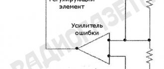
To avoid this, the speaker ground terminal should be connected to the common terminal of the power filter capacitors. Often the speaker terminal is connected to the common terminal of the microcircuit, as shown in the figure:
This connection closes the negative half-wave of the signal into a local loop, eliminating the filter capacitor that could reduce radiated interference and improve system stability.
The figure shows how the ground leakage current of one half-wave of the signal can cause unpleasant noise and distortion if the common wire of the speaker is connected to the output stage of the microcircuit:
Similarly, if on the amplifier board in the power circuits there are bypass capacitors (and they usually are) of a fairly large capacity of several hundred microfarads, then the charging current pulses will also create a potential difference on the common conductor. Therefore, we repeat once again, the best point for connecting the common wire of the speaker system is the common terminal of the power filter capacitors.
↑ Final diagram for connecting LM2596 modules
The scheme is simple and obvious.
With a long-term load of 1 A current, the parts heat up noticeably: the diode bridge, the microcircuit, the module choke, most of all the choke (additional chokes are cold).
Heating to the touch is 50 degrees. When operating from a laboratory power supply, heating at currents of 1.5 and 2 A is tolerable for several minutes. For long-term operation with high currents, a heat sink to a larger chip and inductor is desirable.
Diagram of rectifiers and voltage stabilizers
Below is a schematic diagram of the power supply for my homemade power amplifier.
Rice. 2. Schematic diagram of the power supply for a homemade low-frequency power amplifier.
To power the LF power amplifier circuits, two bipolar rectifiers are used - A1.1 and A1.2. The remaining electronic units of the amplifier will be powered by voltage stabilizers A2.1 and A2.2.
Resistors R1 and R2 are needed to discharge electrolytic capacitors when the power lines are disconnected from the power amplifier circuits.
My UMZCH has 4 amplification channels, they can be turned on and off in pairs using switches that switch the power lines of the UMZCH scarf using electromagnetic relays.
Resistors R1 and R2 can be excluded from the circuit if the power supply is permanently connected to the UMZCH boards, in which case the electrolytic capacitors will be discharged through the UMZCH circuit.
KD213 diodes are designed for a maximum forward current of 10A, in my case this is enough. The D5 diode bridge is designed for a current of at least 2-3A, assembled from 4 diodes. C5 and C6 are capacitors, each of which consists of two capacitors of 10,000 μF at 63V.
Rice. 3. Schematic diagrams of DC voltage stabilizers on microcircuits L7805, L7812, LM317.
Explanation of names on the diagram:
- STAB - voltage stabilizer without adjustment, current no more than 1A;
- STAB+REG - voltage stabilizer with regulation, current no more than 1A;
- STAB+POW - adjustable voltage stabilizer, current approximately 2-3A.
When using LM317, 7805 and 7812 microcircuits, the output voltage of the stabilizer can be calculated using a simplified formula:
Uout = Vxx * ( 1 + R2/R1 )
Vxx for microcircuits has the following meanings:
- LM317 - 1.25;
- 7805 — 5;
- 7812 — 12.
Calculation example for LM317: R1=240R, R2=1200R, Uout = 1.25*(1+1200/240) = 7.5V.
↑ Installation
To mount the module, I used homemade “stands” made of tinned wire with a diameter of 1 mm.
This ensured convenient installation and cooling of the modules.
The posts can get very hot when soldering and will not move like simple pins. The same design is convenient if you need to solder external wires to the board - good rigidity and contact. The board makes it easy to replace the DC-DC module if necessary. General view of the board with chokes from halves of some kind of ferrite core (inductance is not critical).
Despite the tiny dimensions of the DC-DC module, the overall dimensions of the board turned out to be comparable to an analog stabilizer board.
Calculation of the number of turns and winding
To power the remaining electronic units of the amplifier, it was decided to wind several separate secondary windings. A wooden shuttle was made to wind the coils with enameled copper wire. It can also be made from fiberglass or plastic.
Rice. 2. Shuttle for winding a toroidal transformer.
Winding was done with enameled copper wire, which was available:
- for 4 power windings UMZCH - wire with a diameter of 1.5 mm;
- for other windings - 0.6 mm.
I selected the number of turns for the secondary windings experimentally, since I did not know the exact number of turns of the primary winding. The essence of the method:
- We wind 20 turns of any wire;
- We connect the primary winding of the transformer to the ~220V network and measure the voltage on the wound 20 turns;
- We divide the required voltage by that obtained from 20 turns - we find out how many times 20 turns are needed for winding.
For example: we need 25V, and from 20 turns we get 5V, 25V/5V=5 - we need to wind 20 turns 5 times, that is, 100 turns.
The calculation of the length of the required wire was done as follows: I wound 20 turns of wire, made a mark on it with a marker, reeled it off and measured its length. I divided the required number of turns by 20, multiplied the resulting value by the length of 20 turns of wire - I got approximately the required length of wire for winding. By adding 1-2 meters of reserve to the total length, you can wind the wire onto the shuttle and safely cut it off.
For example: you need 100 turns of wire, the length of 20 wound turns is 1.3 meters, we find out how many times 1.3 meters each need to be wound to get 100 turns - 100/20 = 5, we find out the total length of the wire (5 pieces of 1, 3m) - 1.3*5=6.5m. We add 1.5 m for reserve and get a length of 8 m.
For each subsequent winding, the measurement should be repeated, since with each new winding the wire length required by one turn will increase.
To wind each pair of 25 Volt windings, two wires were laid in parallel on the shuttle (for 2 windings). After winding, the end of the first winding is connected to the beginning of the second - we get two secondary windings for a bipolar rectifier with a connection in the middle.
After winding each pair of secondary windings to power the UMZCH circuits, they were insulated with thin fluoroplastic tape.
In this way, 6 secondary windings were wound: four for powering the UMZCH and two more for power supplies for the rest of the electronics.
↑ Conclusions
1. A transformer with a high-current secondary winding or with a voltage reserve is required; in this case, the load current may exceed the current of the transformer winding.
2. At currents of the order of 2 A or more, a small heat sink to the diode bridge and the 2596 microcircuit is desirable.
3. It is desirable to have a large capacity power capacitor, this has a beneficial effect on the operation of the stabilizer. Even a large and high-quality container heats up a little, therefore a low ESR is desirable.
4. To suppress ripple with the conversion frequency, an LC filter at the output is required.
5. This stabilizer has a clear advantage over a conventional compensation one in that it can operate in a wide range of output voltages; at low voltages, it is possible to obtain an output current greater than what the transformer can provide.
6. The modules allow you to make a power supply with good parameters simply and quickly, bypassing the pitfalls of making boards for pulse devices, that is, they are good for beginner radio amateurs.
Denouement
When using two filter capacitors with bipolar power supply, you must ensure that the two half-waves of the signal are summed at one point , as shown in the figure:
Often, using a single capacitor connected between the plus and minus of the power supply can solve this problem. This method works well with 5532 op amps and LM3886 power amplifiers.
When the driver stage and output stage are powered separately, this can cause some instability in the amplifier at high frequencies. The problem is solved by connecting a small-capacity ceramic capacitor between the power pins of the microcircuit:
click to zoom
If the capacity of the bypass (blocking) capacitors is more than 100 µF, their common wire should be connected to the “dirty” ground, since large charging currents can create noticeable interference if the capacitors are connected to the signal ground.
Mono amplifier installation example
Typically, the star in a single-supply amplifier is three-pointed: the signal ground, the power filter capacitor ground, and the dirty ground. An example is shown in the figure:
click to zoom
Here, an amplifier should be understood as both an integrated design and amplifiers based on discrete elements.
As you can see, the signal ground is connected to one beam - the currents here are very small, so there is no need to connect all elements with separate conductors. to the second beam by separate conductors : the output stage, the Zobel circuit, the common terminal of the speaker system and bypass capacitors. The common terminal of the filter capacitor of the power supply is connected to the third beam.
The correct connection of the common wire to the pins of the microcircuits is shown in the figure:
Option "c" is an incorrect option. Due to the resistance of the track, a large current will raise the potential of the low-current common wire relative to the output of the microcircuit, which will lead to an increase in distortion.
To be continued…
The article was prepared based on materials from the magazine “Practical Electronics Every Day”
Author: Jack Roseman
Free translation: Editor-in-Chief of RadioGazeta