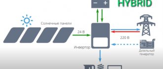
Advantages of using frequency converters
Frequency converters are widely used in a wide variety of production niches and equipment. Such a high demand for such devices is due to the following advantages of their use:
- Reduce starting current. When starting an electric motor using direct starters, a sharp increase in current is observed, the value of which exceeds the rated value by 7-15 times. This has a negative impact on the electric drive and can lead to insulation breakdown, contact burnout and a number of other negative consequences. In addition, this starting method also affects the mechanical components of the system. At the moment of start-up, the working components of the engine are subjected to high loads, which leads to their faster wear. Thanks to frequency converters, it is possible to significantly reduce the starting load on the electric motor, extending its maintenance-free operation.
- Economical. As a rule, the motors that support the operation of ventilation and pumping systems always operate at the same frequency, and pressure and other operating parameters are regulated using fittings (vanes, dampers, etc.). This leads to wasted energy consumption. In the case of using frequency converters, it is possible to adjust the operating parameters of the system by adjusting the intensity of the engine. This makes it possible to use its resources more rationally.
- Increased adaptability. When using frequency converters, it is possible to design automated systems that, according to established algorithms, will correct the operation of the equipment. This reduces the labor costs of production processes and makes them more accurate by eliminating the human factor.
- Maintainability. If the frequency converter breaks down, you can take it to a workshop, where a technician will replace the failed parts. True, this only applies to the electrical converting unit - with control units everything is much more complicated and they are more demanding in terms of restoration.
Frequency converters are the optimal solution for organizing a wide variety of production processes and debugging working equipment based on which electric motors are used.
How to design a frequency drive with your own hands
When designing an actuator, the emphasis should be on ensuring that the design is efficient and inexpensive. Protection and flexibility are also needed. As a result, an inverter will be produced that has the following functions:
- motor magnetization;
- complete stop of the engine;
- frequency increase speed from 5 to 50 Hz per second;
- maximum power with module 750 W;
- output frequency from 5 to 200 Hz;
- reverse input;
- the ability to change the U/F characteristics;
- DC link voltage control;
- volt additives from 0 to 20%.
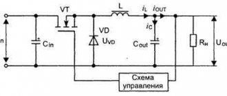
When power is supplied, the capacitance of the DC link is charged. When it reaches 220 V, a certain delay will occur and the precharge relay will turn on, and a single LED will light up. We can assume that the drive is completely ready for operation. To control the frequency converter, there are six inputs.
device diagram
What algorithm does the device use?
From the very beginning, the microcontroller is configured to work with an electric motor with a rated power of 220 V, and the field rotation frequency is 50 Hz - we are talking about a regular frequency generator. The frequency picks up at a speed of somewhere around 15 Hz per second. Volt additive is set at 10% with a magnetization duration of 1 second. This value is unchanged.
The duration of DC braking is 1 second. Do not forget that the amount of electricity at the moment of magnetization and braking changes at the same time. Frequency converters are scalar. As the output speed increases, the output current also increases.
If the command on the resistor is changed while the engine is rotating, it can only change when the command is given again. Roughly speaking, data from the resistor will be read in the absence of these two signals. If you plan to regulate the speed using a resistor during operation, then you will need to install a jumper.
Features of settings and regulation
Before turning on the drive for the first time, you need to configure it and check whether all electronic components are installed correctly and the voltage divider for the DC link is configured. If at 100 volts the link is 1 volt at 23, then the setup can be considered complete. Before applying current, the board is washed and the remaining rosin from the solder side is removed using alcohol or solvent, and the board is varnished.
The drive has factory settings - they are suitable for both a 220V engine and a 380V engine. To set the factory settings for a 220 V engine with a frequency of 50 Hz, follow these steps:
- The drive turns on.
- Readiness is expected.
- Press and hold button B1 until the LED flashes, then the button can be released.
- The speed selection command is given. When the LED no longer blinks, the command is removed.
- The drive can be considered configured.
During these settings, the parameters of the nominal engine frequency, acceleration intensity, additive volts, and braking intensity are recorded automatically. It turns out that while the LEDs are blinking, the drive is being configured.
pay
Regarding nutrition
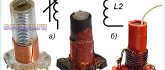
It is best to use a transformer, because it is more reliable than all other options. Installation of a protective diode is required. What engines can be connected to homemade frequency converters? In this case, the module is of great importance. It should be taken into account that some modules are designed for small pulse currents and have built-in protection at the level of 15 A. And this is extremely low. If we are talking about a 50 Hz motor, then this is quite enough. When you have a high speed spindle, they often have low winding resistance. These modules can be penetrated by pulsed currents.
Intermediate chain
The intermediate circuit acts as a kind of storage facility from which the electric motor receives energy through the inverter. Depending on the combination of inverter and rectifier, the intermediate circuit can have one of the following formations:
- Inverter power supply. In this case, the intermediate circuit contains a powerful inductive coil, which converts the rectifier voltage into a varying direct current. The motor voltage itself is determined by the load. This type of circuit can only work with controlled rectifiers.
- Inverters are voltage sources. In this case, a filter is used in the intermediate circuit, which includes a capacitor. It smoothes out the voltage coming from the rectifier. Such circuits can work with any type of rectifier.
- Circuit of varying direct voltage. In this case, a breaker is installed in front of the filter, which contains transistors that switches off and on the voltage supply from the rectifier. In this case, the filter smooths out the rectangular voltages after the chopper, and also maintains a constant voltage at a given frequency.
Part 2. Nuances
— How to choose the correct frequency control range and which control method to choose?
Petr Ivlev : “The use of an inverter allows you to regulate the speed of the electric motor from zero to the nominal value and above. It is important to remember that the converter can provide an output voltage equal to the supply voltage. Figuratively speaking, if the motor needs 690 V, and the inverter is designed for 380 V, this is a fundamentally incorrect selection of equipment.”
About control methods
There is a lot of theoretical information on the Internet about which option is better. In fact, you should base your choice not on assessments of the control method, but on the area of application of the frequency converter. In equipment that works with cranes, lifting mechanisms or broaching machines, the vector method is used. In pumps and fans, that is, in those mechanisms where the speed practically does not change, a scalar . Both of these methods solve the same problem: adjusting speed and changing torque.
— What is a PID controller, control inputs/outputs, and how important is it?
Petr Ivlev : “The proportional-integral-derivative controller (PID controller) controls external processes by analyzing feedback signals received by the frequency converter. This regulator is found in 95% of modern frequency converters.”
The simplest example of its use: it is required to maintain a constant pressure in the pipe of 5 Bar. The inverter reads signals from sensors, and the PID controller, using mathematical algorithms, ensures the required operating mode of the inverter.
The inverter reads signals from sensors, and the PID controller, using mathematical algorithms, ensures the required operating mode
Regarding inputs and outputs
Today, most frequency converters have analog and digital inputs/outputs, a serial interface, etc. as standard. This set of functions allows you to integrate the inverter into most automatic systems, without restrictions in the choice of methods for controlling the converter.
- Discrete (digital) control is considered the simplest; these inputs are used to transmit basic commands: starting or stopping the electric drive, speed control, switching between inverter operating modes. Such outputs report malfunctions, reaching specified frequency and current limits, give commands to turn on slave electric drives, etc. You can set the required function for one discrete input, choosing from more than several dozen.
- Analog control solves other problems. For example, it provides smooth regulation. Also, this control method allows for constant monitoring and control of the status of the necessary system parameters. The signals arrive at the inverter input from the corresponding sensors.
- Serial interface control is used to build a complex automated system. This method allows you to control several frequency converters at once, and they can be located far from each other. This method significantly reduces the number of wires, while simultaneously increasing the possibility of transmitting information. The most universal and, accordingly, popular and reliable interface (protocol) for connecting to an inverter today is Modbus (RS485).
— What else should you pay attention to when choosing a frequency converter?
Artem Moshechkov : “Of course, on the functionality, ergonomics of the equipment, the availability of additional features, and a clear interface. An important issue for many is the operating conditions and installation of the inverter. For example, the CONTROL-A310 and L620 IEK® series frequency converters require sufficient free space for cooling, while the ONI-A400 can be mounted wall-to-wall. But all these series are distinguished by their small dimensions and unpretentious installation.”
In some lines it is possible to use standard twisted pair UTP cat. 5e for remote mounting of the included control panel, which makes installation of the control panel as simple as possible and up to 10 times cheaper compared to converters that use special switching cables.
Pay attention to the operating conditions: for example, if it is necessary for the frequency converter to operate reliably in high humidity, it is worth considering the CONTROL-L620 IEK® series - this equipment can be operated without additional cooling at relative humidity up to 95% and temperatures from -10 to +40 °C. And the special coating of the boards, in accordance with industry standards, allows these converters to be used in harsh conditions.
Be sure to ask what power switches are used when assembling the inverter - one of the most reliable are IGBTs manufactured by Infineon. They can significantly increase the reliability and fault tolerance of equipment.
The frequency converter control system must be intuitive, functional, and variable. In advanced models, such as the ONI-M680 series, the control signal source can be a keypad, industrial network, digital inputs and pulse input. It is possible to connect actuators, sensors, programmable logic controllers. Some inputs and outputs can operate in different modes.
And, of course, certification and manufacturer’s warranty are important. If we talk about those series on the basis of which we analyzed the operating principles of the inverter, then the CONTROL IEK® line has an estimated service life of 7 years, a warranty of two years. All converters produced under this brand have GOST certificates of conformity. The ONI® family of frequency converters has similar performance.
Design. Types of converters
A frequency electric drive has a number of circuits that include a transistor or thyristor. The basic element of the electronic circuit is a microprocessor, which is responsible for the operation of additional circuit elements and ensures the performance of a large number of additional tasks.
A frequency converter is a group of rectifiers, as well as inverters that transform alternating currents into direct currents.
Single-phase frequency converter is a high-tech device. Its main task is to convert the operating voltage of the network into household voltage (220 V). With this transformation, a voltage pulse is performed at the required frequencies (1 – 1000) Hz.
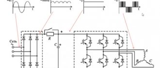
The frequency converter for the electric motor creates voltages with the specified parameters. The frequency converter works as follows:
- First, the voltage of the electrical network is rectified, as well as pulse reduction and harmonic filtering.
- DC voltage is supplied from the rectifier to the inverter circuit, where it is transformed into alternating voltage with varying amplitude and frequency.
Fig. 1 Schematic diagram of a frequency converter
The role of power elements is often performed by IGVT transistors. By changing the frequency, you can change the rotation speed of the electric motor (M).
The frequency converter is divided into two large types:
With direct communication.
Their distinctive feature is a thyristor rectifier, where individual thyristors alternately open and close and are alternately connected to the stator coil.
Rice. 2 Graphical representation of the converter voltage
The output voltage of the sinusoid forms a sawtooth shape with a frequency of about 1 – 40 Hz. The scope of application of this kind of converters is considered limited due to the fact that non-lockable thyristors require more complex control circuits. Which brings with it a higher cost of equipment.
Such frequency converters operating with high currents and voltages have an efficiency of about 95-98%. Also, high-voltage frequency converters have a higher cost compared to low-voltage ones.
If we compare a thyristor converter with a transistor electric drive that has similar power, then the second device will have significantly smaller dimensions, lighter weight and will be more reliable.
With a pronounced DC link.
This type of sensor is much more common in modern devices whose purpose is to regulate frequency.
The transformation occurs in 2 stages:
- first, the mains voltage is rectified and filtered;
- then the signal is supplied directly to the inverter, where the current of the required frequencies and amplitudes is transformed into alternating current.
The efficiency of such a transformation decreases, while the dimensions of the device increase. The sinusoidal signal is provided by an independent voltage and current inverter.
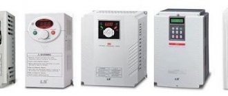
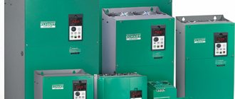
Available models
In many areas, asynchronous motors are used, the operation of which is characterized by high stability and safety. This is especially important, since any device has its own individual characteristics, which is why we need inverters that optimize their power supply parameters. The new line of equipment includes:
- Emotron FDU 2.0 is the latest generation frequency converter produced by the Swedish company Emotron. The device operates in the range from 0.75 to 1.6 kW and is designed for different voltage groups: 3x380 V, 3x500 V, 3x690 V. The inverter is mainly used for pumping or ventilation equipment.
- Emotron CDU/CDX series is equipment designed to control the operation of an elevator. Inverters of this brand are installed both on new elevators and for modernizing old structures. Mounted in the engine room or directly next to the shaft.
- “Leader” - a frequency converter is used to control asynchronous motors in pumping and ventilation equipment, mills, crushers, centrifuges, and so on. The device eliminates the presence of dynamic shocks during startup, which makes it possible to increase the service life of the engine and drive mechanism by 1.5-2 times.
- Easydrive Smart series is an inverter with an output power from 1 Hz to 2 kHz. It is distinguished by automatic determination of electric motor parameters when the mechanism is stationary. The device has seven programmable switching inputs that allow you to perform up to 30 functions.
All models allow you to change the direction of rotation of the electric motor shaft, save basic energy resources, and reduce operating costs.
Vector control of frequency converter
The principle of operation of vector control is as follows: it affects the magnetic flux, changing the direction of its “spatial vector” and regulating the rotor frequency of the field.
You can create a working algorithm for a frequency converter with vector control using two methods:
Touchless control.
It is carried out by assigning alternation dependencies between sequences of pulse-width modulations of the inverter for pre-compiled algorithms. The regulation of the amplitude size and output frequency that the voltage has is carried out according to the slip and load current, but the feedback from the rotor rotational speed is not taken into account.
Flow regulation.
The operating currents of the device are adjustable. At the same time, they are decomposed into an active and reactive component. This makes it easier to make corrective changes to the workflow (changes in amplitudes, frequencies, vector angles of the output voltage).
In general, the vector control circuit is more suitable than others for dynamically adjusting the rotating torque of a three-phase asynchronous motor.
Specifications
Frequency converters should only be used based on their performance characteristics. The main technical characteristics that you need to pay attention to include:
- Voltage range of the supplied current. There are various versions that can operate at voltages from 100 to 120 V, from 200 to 240 V. This indicator is decisive when choosing the most suitable model.
- Rated power of the electric motor connected to the circuit. As a rule, the indicator is measured in kW.
- Full motor power.
- Rated output current.
- The output voltage is often no more than the voltage from the power supply, but it can be less.
- Output frequency range
- An indicator of the permissible current at the input.
- Frequency of electricity at input.
- Maximum deviations from the indicators that are acceptable in certain cases.
Such parameters must be specified in the specification of the frequency converter. If, for example, the supply voltage is not taken into account, the device in question will be damaged.
Frequency converter device
In most cases, the frequency converter device is based on a double conversion circuit. The units include: a DC link (uncontrolled rectifier), a power pulse inverter and a control system. In turn, the DC link includes an uncontrolled rectifier and a filter. Here the alternating voltage of the network is converted into direct current voltage. The power three-phase pulse inverter includes six transistor switches and each motor winding is connected through a specific switch to the positive/negative terminals of the rectifier. By means of an inverter, the rectified voltage is converted into a three-phase variable value of the required frequency and amplitude, applied to the stator windings of an electric motor.
Power IGBT transistors are used as switches. If we compare them with thyristors, the former have a higher switching frequency, which makes it possible to produce a sinusoidal output signal with minimal distortion. Information on how to connect and configure the frequency converter will be discussed below. This section only shows the general structure of the frequency converter for reference.
Energy losses in a frequency converter and ways to reduce them
Let's consider the issue of heat generation in the inverter part of the converter. What determines the losses of a transistor?
Fig.8. Energy loss
Let's take a conventional IGBT transistor, which is connected to a circuit with a voltage of 500 volts, limiting the resistor.
Closed state: there is no voltage at the gate, the voltage at the collector is equal to the mains voltage, there is no current, leakage is negligible, and there is no heat generation. We open the transistor using a voltage of 10 volts at the gate, this is the standard voltage for almost all transistor modules. The transistor does not switch to the open state instantly; each transistor has a parameter called on time or off time. A typical value for the most common transistors is 0.2 microseconds. The time is short, but during this time there is both a voltage on the transistor crystal, which quickly drops, and an increasing current value, which also does not increase instantly. At this point, losses occur. And the higher the PWM frequency, which we talked about earlier, the more often the transistor turns on and off, the more heat is generated due to switching losses.
When the transistor has opened, a static mode has been established for some short time, heat generation continues: it occurs due to the fact that at the moment of the opening state, the voltage on the transistor is also not zero, it is determined by losses on the crystal in the open state. Its typical value is 1.5 volts. It may vary slightly depending on the manufacturing technology of the transistor, etc.
At this moment, heat generation also exists, but we cannot do anything about the losses in the on-state, the maximum is to use transistors with a lower voltage in the on-state. We can combat switching losses by reducing the PWM frequency. This is useful if the inverter is located in a closed cabinet, where it gets hotter. By lowering the PWM frequency, we can reduce losses on the converter and reduce its temperature.
The total loss of the frequency converter in the form of heat is about 3%.
Rectifier losses occur through open diodes. The voltage drop across the open diode, as well as the rectified current flowing through it, lead to its heating. The DC link, consisting of large-capacity electrolytic capacitors, also heats up because the charge and discharge process is constantly occurring. Losses also include the frequency converter’s own needs: the operation of cooling fans, electronic circuits, secondary power sources, and so on.
Caring for the Transducer
To extend the service life of the inverter, you should take proper care of it:
- Monitor the accumulation of dust on the internal elements and promptly clean the device using a compressor.
- Make sure that the components used in the mechanism are working properly and replace them if the need arises.
- Maintain adequate operating temperature (no more than +40°C) of the mechanism and voltage level on the control bus.
- Regularly (at least once every 3 years) update the layer of thermal paste on the power components of the device.
- Maintain moderate humidity levels if possible.
How to choose a frequency converter?
There are several main parameters that you need to pay attention to when choosing a frequency converter:
Power. This parameter of the frequency converter must correspond to the power of the engine with which it will be used. You should choose a device whose power will correspond to the rated current. It is simply pointless to buy a frequency converter with very high characteristics, because it will cost much more, and problems may arise with setup. Load type. It all depends on how the unit to which the frequency converter will be connected operates. For example, with fan loads there are no overloads, but in the case of press operation, the current can exceed the rated values by 60 percent or more. Accordingly, it is necessary to take this into account when choosing and leave a certain “move” reserve. Engine cooling type. Engines can be equipped with forced cooling systems or have self-blowing. In the second case, special blades are attached to the rotor impeller, which rotate with it and blow over the engine. Accordingly, the normal degree of airflow in this case directly depends on the rotation speed. If the engine runs for a long time at a reduced frequency, this may lead to overheating. Accordingly, it is better to take care of additional cooling if the frequency change is more than 10% of the nominal value. Input voltage. This indicator determines at what voltage the frequency converter is capable of operating. It’s not enough to know that the network voltage is usually about 380 V. Jumps often occur in the range of +-30%. In addition, in networks where a large number of power equipment are connected, surges of 1 kV often occur. Accordingly, the wider the operating voltage range of the frequency converter, the more reliable it will work. Braking method. Stopping the engine can be done either by an inverter bridge or by an electrodynamic method. The first method is more suitable for precise and fast braking, and the second - in mechanisms with frequent braking or when a gradual stop is necessary
You should definitely pay attention to this. Environment and protection. Typically, the passport of the frequency converter indicates the conditions under which the device should be used
For example, waterproof models comply with the IP 54 standard - they are resistant to moisture and can be used in rooms with steam fumes and high humidity. Control type and interfaces. It is imperative to pay attention to the availability of suitable connectors, as well as control capabilities - some models are designed for on-site installation, while others are designed for a separate control room.
If you have never worked with frequency converters, it is better to seek advice from a specialist.
How to choose
For manufacturers of frequency converters and other electronic equipment, the main tool for conquering the market is price. In order to reduce it, they create devices with a minimum set of functions. Accordingly, the more versatile a particular model, the higher its price. For us, this is of great importance for the reason that for efficient and long-term operation of the engine, an inverter with certain functions may be required. Let's look at the main criteria you should pay attention to.
Control
According to the control method, frequency converters are divided into vector and scalar. The former are much more common today, but have a higher price compared to the latter. The advantage of vector control is its high control accuracy. Scalar control is very simple, it can only keep the ratio of output voltage and frequency at a given value. It is advisable to install such a converter on a small device without a high load on the motor, for example, a fan.
Power
Of course, the higher this value, the better. By the way, in this matter the numbers are not so important. Pay more attention to the company - your equipment to each other, the more efficiently it will work. In addition, the use of multiple converters from the same brand supports the principle of interchangeability and ease of maintenance. Consider whether there is an appropriate service center in your city.
Mains voltage
In this case, the same principle applies as in the previous section - the wider the operating voltage range, the better for us. Domestic electrical networks, unfortunately, are poorly familiar with the concept of “standard”, so it is better to protect the equipment as much as possible from possible surges. A voltage drop is unlikely to lead to serious consequences (the converter will most likely simply turn off), but a large increase is dangerous - it can damage the device as a result of the explosion of electrolytic network capacitors.
Frequency adjustment range
In this case, you should rely solely on the requirements of production and specific devices. For example, for equipment such as grinding machines, the maximum frequency value (from 1000 Hz) is important. The standard lower limit is considered to be a ratio of 1 to 10 relative to the upper limit. In practice, converters with a range from 10 to 100 Hz are most often used. Please note that only converter models with vector control have a wide adjustment range.
Control inputs
Discrete inputs are used to transmit control commands in converters. They are used to start the engine, stop it, brake it, reverse it, etc. Analog inputs are used for feedback signals that monitor and adjust the drive directly during operation. And digital ones are used to transmit high-frequency signals generated by encoders (rotation angle sensors).
In fact, the more inputs, the better, but a large number of them not only makes setting up the device difficult, but also increases its cost.
Number of output signals
The discrete outputs of the converter are necessary to output signals indicating the occurrence of problems, such as overheating of the device, deviation of the input voltage from the norm, accident, error, etc. Analog outputs are needed to provide feedback in complex systems. The principle of choice is the same: look for a balance between the number of signals and the cost of the device.
Control bus
The connection diagram for the frequency converter will help in finding a suitable control bus - the number of outputs and inputs should be at least equal, but it is better to buy a bus with a small margin - this will make it much easier for you to further improve the device.
Overload capabilities
It is considered normal if the power of the frequency converter is 10-15% higher than the engine power. The current should also be slightly higher than the motor rating. However, such selection “by eye” is recommended only in cases where there is no necessary technical documentation for the engine. If available, carefully read the requirements and select the appropriate converter. If shock loads are important, the peak current of the inverter should be 10% greater than the specified value.
How is the frequency converter connected?
If we consider the installation of a frequency converter schematically, then the whole process comes down to connecting the contacts of the device itself, the electric motor and the control fuse block. It is enough to connect the wires of all elements, connect the engine to the network and start it.
At first glance, there is nothing complicated about this, but, in fact, the installation procedure has some of its own nuances:
It is very important that a fuse is installed in the circuit between the frequency converter itself and the power source. It will allow you to promptly turn off devices in case of voltage surges, maintaining their functionality
It is noteworthy that when connecting to a three-phase network, it is necessary that the fuse itself is also three-phase, but has a common disconnect lever. This will make it possible to turn off the power on all phases at once, even if only one has a short circuit or overload. If the converter is connected to a single-phase network, then the fuse must be single-phase. In this case, when making calculations, it is necessary to take into account the current of only one phase, but multiplied by 3. It is always worth remembering that the instructions for almost any converter indicate the requirements and standards for its installation. You need to familiarize yourself with them before starting work. The phase outputs of the frequency converter are connected to the contacts of the electric motor itself. In this case, depending on the voltage of the frequency converter, the motor windings may have a “star” or “triangle” formation. There are usually two voltage values marked on the motor housing. If the frequency driver corresponds to the smaller one, then the windings are connected in a “star”, if the larger one corresponds to a “triangle”. All this information is usually printed in the instructions. Almost every frequency converter comes with a remote control panel. It is not a mandatory element of the circuit, because the device itself also has its own controls, but it can significantly simplify the work with the equipment. The remote control can be mounted at any distance from the frequency generator. This is usually done as follows: frequency converters that have a low degree of protection are located away from the engine, and the remote control itself is taken directly to the workplace near the equipment.
An equally important stage in installing a frequency converter is its test run. It works according to the following scheme:
- After connecting all elements of the system (fuse, control panel, frequency converter, motor), it is necessary to move the handle on the control panel to the active position by several degrees.
- Switch the fuse switches to the “ON” position. After this, the indicator lights on the frequency converters should light up, indicating that the equipment is connected correctly, and the motor should begin to rotate slowly.
- If the motor shaft begins to rotate in the opposite direction, it is necessary to reprogram the frequency converter itself for reverse movement. Almost all modern devices support this function.
- Move the control handle gradually and monitor the engine operation - the shaft speed should increase as you move the handle.
If no problems were found during the test run, then you have done everything correctly and the system can be included in the workflow.
Connection and configuration rules
For the inverter of an asynchronous electric motor to operate fully and efficiently, it must be correctly connected and configured . The required circuit breaker is installed in the circuit in front of the frequency switch. If this is a three-phase network, then the switch must be designed for a voltage of 380 V, and the current strength must correspond to the motor rating.
In the event of an emergency in the network in one phase, the remaining current-carrying conductors will also be disconnected. The magnitude of the rupture current must correspond to the value in a separate phase of the electric motor. When using a frequency converter in a single-phase network, a single circuit breaker is installed, rated three times the current value.
In both cases, it is not recommended to install circuit breakers into the gap of the grounding or neutral conductor; only direct connection must be made.
In order for the connection to be made correctly, the current-carrying wires coming from the converter must be connected to the corresponding motor terminals.
The stator windings of the mechanism are connected “star” or “delta” , depending on the voltage supplied from the inverter. If it coincides with the smallest value on the motor housing, then the “triangle” circuit is used. If the high voltage value coincides, the connection is made according to the “star” circuit.
Next, the inverter is connected to the controller and control unit, which is usually supplied with the converter. All connections are made according to the diagram included in the equipment operation manual. After completing the fastening work, the machine turns on and power is supplied to the inverter, which will be indicated by a light on the remote control.
To start the frequency generator, the start button is turned on and the corresponding handle is turned. The electric motor will slowly begin to rotate. If you need to change the rotation in the opposite direction, then there is a corresponding toggle switch on the remote control. To achieve the required number of engine revolutions, the required voltage or rotation frequency is set, depending on the equipment model.
Operating principle of the frequency converter
The operating principle of the frequency converter is based on the operating features of an asynchronous electric motor. In an electric motor of this type, the rotation frequency of the magnetic field (n1 value) depends on the frequency of the supply voltage. In the case when the stator winding is powered by a three-phase voltage having a frequency f, a rotating magnetic field is generated, the rotation speed of which is determined by the formula below:
, Where
p is the number of pairs of stator poles.
The transition from the field rotation speed ω1, which is measured in radians, to the rotation frequency n1 (rpm), is performed according to the formula:
, Where
60 is the dimension conversion factor.
If we substitute the field rotation speed ω1 into this equation, we obtain the following equality:
From this it is easy to conclude that the rotor speed of an asynchronous electric motor depends on the frequency of the supply network voltage. It is this dependence that reflects the whole essence of the frequency regulation method. The frequency converter for the electric motor changes the frequency of the supply voltage at the input and, as a result, regulates the rotor speed. We emphasize that the output frequency in modern frequency converters varies over a wide range, which means that this value can be either lower or higher than the frequency of the supply network.
The frequency converter for the electric motor, the principle of operation of the power unit of which formed the basis for the classification below, corresponds to the following parameters:
- Converters with a clearly defined intermediate DC link.
- Converters with direct coupling (no intermediate DC link).
By historical standards, direct-coupled frequency converters were the first to appear. In these units, the power part is a controlled rectifier made using thyristors. The control node, in turn, unlocks groups of thyristors, thereby generating an output signal. Today this conversion method is not used in new developments.
How does this class of converter work? Here, double conversion of electricity is used: the input sinusoidal voltage (values L1, L2, L3 in the figure) with a constant amplitude/frequency is rectified in the rectifier unit (BR), filtered and smoothed in the filtering unit (BF), as a result, we obtain a constant voltage. The presented unit is called the DC link.
The conversion unit (BD) is responsible for solving the problems of generating a sinusoidal alternating voltage with an adjustable frequency. The role of electronic switches that generate the output signal is performed by bipolar transistors with an insulated gate IGBT. The process of controlling the above blocks occurs according to a pre-programmed algorithm by a microprocessor module or logical block (BL).
The diagram below shows that frequency converters can be powered from an external DC link. In this case, the protection of the frequency generator is carried out using high-speed fuses
It is important to note that the use of contactors for DC link power is not recommended. The fact is that during contactor switching, an increased charging current occurs and the fuses can burn out
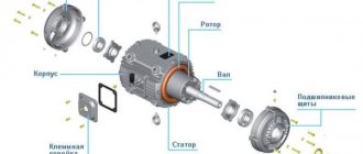
Structure and features of the inventory
After the rectifier, the voltage is supplied to the inverter. The inverter is the most complex and important part of the frequency converter. From the output of the inverter, the signal goes directly to the electric motor. The voltage form at the inverter output is a set of rectangular pulses of different widths and a certain duration. This is how the power part of the frequency converter is built.
The device circuit also includes low-current circuits that help the interaction of all the main parts of the inverter. In particular, there is a central processor, which is, in essence, the brain of the converter and controls both the operation of the inverter and other parts of the device. The processor receives information about the output current from current sensors located on the output circuits of the inverter. The signal from the current sensors is processed, and the processor then generates a control algorithm so that the converter can operate under user-specified conditions. There is also a power supply for its own needs; it powers both the processor part and the part responsible for measuring the output current and measuring the voltage on the DC link. In addition, there is a block of driver chips, which in turn control the transistors of the inverter part, and a number of auxiliary elements.
Rice. 2. Schematic diagram of the inverter
Let's consider the basic design of the inverter part. The main elements of the power part of the inverter are IGBT transistors - powerful, specially designed for operation in switching mode. This is a hybrid of field-effect and bipolar transistors. The control part is an insulated gate (like a field gate), and the power part replicates the bipolar device, which has a collector-emitter.
Power elements are produced in the form of a dual module, consisting of two power transistors connected in series. Each of the transistors is shunted by a diode in the opposite direction. Since the output must have 3 phases, the inverter design has 3 arms (see Figure 2).
Rice. 3. Equivalent circuit of transistors
To better understand the principle of operation, consider an equivalent circuit where each transistor is replaced by a conventional switch. The diagram (Fig. 3) shows 6 switches (transistors) and an electric motor.
Let's study how output currents are formed in the motor windings. The central processor is responsible for controlling the transistors (switches in the diagram). It switches them strictly according to a specific program, which is initially set by the algorithm of its action.
The diagram shows the operation of keys No. 1, No. 4, No. 6. Please note that it is strictly forbidden to have a situation where both the upper and lower keys are closed in one arm - this will result in a short circuit and failure of the product. In the situation shown in the diagram, current flows through open switch No. 1, then enters winding A of the electric motor, exits windings B and C, and through open lower keys No. 4 and No. 6 goes to the negative link.
In order to change the current in winding C, you need to switch the switches of the middle arm. The current will still flow through open switch No. 1, and will go through winding B and switch No. 6 to the negative arm. In this case, at the same time, through closed switch No. 3, the incoming current through winding C goes negative. By changing the position of the open and closed keys, you can change the current in the motor windings. If this is done according to a certain program, you will get a variable current, as when the engine is running from the mains, that is, there will be a smooth flow of one phase to another.
Rice. 4. Current flow in the inverter
Now, instead of a simplified circuit with switches, let's consider how current flows in a circuit of transistors using the example of a real inverter (Fig. 4). At its core, this process is no different from the key mode discussed earlier, except that we are dealing with a real motor, which, in principle, is an inductive load.
At the moment the key is closed, the inductance of the motor will not allow the current to stop instantly due to the phenomenon of self-induction. This residual current is extinguished by reverse diodes, which are connected to closed transistors (see Fig. 4), i.e. at the moment of turning off (closing) the transistors, the residual current flows through the freewheeling diodes, thus preventing voltage surges on the switch.
But since the transistor acts as a switch, it can either supply full voltage to the motor or not supply it at all. In practice, it is necessary to obtain a certain smooth voltage of a sinusoidal shape, variable both in magnitude and frequency, in order to be able to control the rotation speed of an asynchronous motor.
Frequency converter device
In most cases, the frequency converter device is based on a double conversion circuit. The units include: a DC link (uncontrolled rectifier), a power pulse inverter and a control system. In turn, the DC link includes an uncontrolled rectifier and a filter. Here the alternating voltage of the network is converted into direct current voltage. The power three-phase pulse inverter includes six transistor switches and each motor winding is connected through a specific switch to the positive/negative terminals of the rectifier. By means of an inverter, the rectified voltage is converted into a three-phase variable value of the required frequency and amplitude, applied to the stator windings of an electric motor.
Power IGBT transistors are used as switches. If we compare them with thyristors, the former have a higher switching frequency, which makes it possible to produce a sinusoidal output signal with minimal distortion. Information on how to connect and configure the frequency converter will be discussed below. This section only shows the general structure of the frequency converter for reference.
Preparing to connect
Before connecting, you must make sure that the converter model corresponds to the design one, and all the characteristics of the frequency regulator match the parameters of the electric motor. Also, the voltage in the supply network should not be lower or higher than the rated voltage of the frequency converter. Next, choose a location to place the converter. It must satisfy the following conditions:
- The class of protection of the housing from moisture and dust must correspond to the location of the frequency regulator. Most devices are IP20 rated and are intended for installation in rooms with low humidity, ventilated electrical automation cabinets, and drive control panels. IP54 and IP65 frequency units can be installed in open areas near motors. This rule also applies to external control panels that are supplied with frequency converters from many manufacturers.
- When installing in cabinets, it is necessary to ensure the required distance from the walls and between other frequency converters and automation devices that heat up during operation. The distance depends on the power of electrical devices. The fan power must correspond to the number of frequency converters and other electrical devices and apparatus placed in one cabinet to ensure sufficient heat dissipation.
- The frequency regulator is installed at a sufficient distance from sources of powerful electromagnetic fields and strong vibrations. If this condition cannot be met, the devices are installed in shielding cabinets on vibration-damping supports. The device is mounted on a flat surface made of non-flammable material, in a place where exposure to direct sunlight is excluded.
- The climatic design of the frequency generator must also correspond to the temperature range, altitude above sea level, humidity and other operating conditions.
How to choose an inverter before buying it
Before choosing a frequency converter, check the electrical compatibility with the motor and load capacity (power).
Rice. No. 1. Block diagram of the operation of a system of pumping units from a VFD frequency converter.
When operating a frequency converter with one motor, the choice is made depending on the rating characteristics. When choosing, the following indicators are taken into account:
- According to the passport, the power of the inverter and the electric motor must be equal. This parameter is valid when using motors with two pairs of poles (2p=4), with rotation speeds up to 1500 rpm, with constant torque. It also applies to inverters that can cope with an overload of 150% (conveyors, conveyor belts) and for converters operating with an overload of 120% (fans, centrifugal pumps).
- The rated current must be equal to or greater than the continuous actual current consumed by the motor (load current).
The motor acceleration time at a starting current of 150% is 120% for converters specializing in pumping units, from the rated inverter usually should not exceed 60 seconds.
- The input voltage of the network must satisfy the converter; it must maintain its functionality even with any voltage deviations from the norm.
- The frequency regulation range that the inverter can support must satisfy the high-speed mode of the motor.
- The presence of discrete control inputs is necessary for entering various types of commands programmed by the user. Analog ones are also needed; they are used to input task signals and for feedback. Digital inputs are also required for high-frequency signals coming from encorders or digital speed and position sensors.
- A number of output signals are used to create complex circuits for a pumping station system.
- Possibility of operational control in operating mode, these can be control inputs using a remote control. Or control via a serial communication bus via a controller or computer. Maybe it will be combined control.
- The choice of converter depends on the preference for the motor control method, scalar or vector control. Depends on separate vector motor control or scalar control - maintaining one constant ratio of output voltage to output frequency. For pumping units, the vector control method is more typical.
- More precise criteria for choosing a frequency driver include the parameter that determines the operation of the engine at steady speed. When the converter operates with one motor, the required power for starting is calculated by the formula:
Rice. No. 2. Formula for calculating total starting power.
The motor current consumption from the converter at a mains voltage of 220/380V is calculated using the formula:
Rice. No. 3. Calculation of mechanical characteristics of the engine.
Rice. No. 4. A table of inequalities that must be observed when choosing an inverter for operating one frequency drive with several motors.
Operating principle
If we explain the principle of operation of a frequency converter, then we can say that the use of this device allows you to effectively and efficiently control the operation of powerful asynchronous electric motors.
The equipment is a variable frequency drive (VFD), due to which the technical characteristics of machines and mechanisms have been improved. To change the speed of the motor shaft, it is necessary to adjust the amplitude of the voltage and frequency. The operating principle of the frequency converter is based on two methods:
- Scalar control - allows adjustment according to a linear law, when the amplitude and frequency depend proportionally on each other. That is, a change in frequency affects the amplitude of the incoming voltage, which affects the torque and power factor of the mechanism. It is very important that the load torque on the motor shaft remains the same, and the ratio of voltage to output frequency remains unchanged.
- Vector regulation - allows you to maintain a constant load at any frequency changes. Provides more precise control and the electric drive responds more smoothly to changes in output power. It should be taken into account that the rotation torque is affected by the magnitude of the stator current, or more precisely, by the magnetic field that it creates.