Preparation of materials
Before starting assembly, you must ensure that you have the necessary materials:
- insulating tape;
- thermal and superglue;
- battery;
- several bolts;
- bicycle spoke;
- wire made of copper material;
- metal plate;
- nut and washer;
- plywood.
It is necessary to prepare several tools, including pliers, tweezers, a knife, and scissors.
Why are commutator motors often used in everyday life?
If we take the 220V phase, the principle of operation of the electric motor on the collector allows us to produce devices 2-3 times less massive than when using an asynchronous design
This is important when making appliances: hand blenders, mixers, meat grinders. Among other things, it is difficult to accelerate an asynchronous motor above 3000 rpm; for brushed motors there is no specified limitation
What makes the devices the only ones suitable for implementing designs of centrifugal juicers, not to mention vacuum cleaners, where the speed is often no lower.
The question of how to make an electric motor speed controller disappears. The problem was solved long ago by cutting off part of the supply voltage sinusoid cycle. This is possible, because it makes no difference to the commutator motor whether it is powered by alternating or direct current. In the first case, the characteristics drop, but the phenomenon is tolerated due to obvious benefits. The commutator type electric motor operates in both the washing machine and the dishwasher. Although the speeds are very different.
It's easy to reverse too. To do this, the polarity of the voltage on one winding changes (if both are touched, the direction of rotation will remain the same). Another problem is how to make an engine with a similar number of components. It is unlikely that you will be able to make the collector yourself, but rewinding it and selecting the stator is quite possible. Note that the rotation speed depends on the number of rotor sections (similar to the amplitude of the supply voltage). But the stator has only a couple of poles.
Manufacturing
First, the wire is wound uniformly. It is carefully wound onto a reel. To make the process easier, you can use a base, for example, a rechargeable battery. The winding density should not be high, but light is also not needed.
The resulting coil must be removed from the base. Do this carefully so that the winding is not damaged. This is necessary to make a speed controller for the engine with your own hands. The next step is to remove the insulation at the ends of the wire.
At the next stage, they make a frequency converter for the electric motor with their own hands. The design is simple. A hole is drilled in 5 plates with an electric drill, then they should be put on a bicycle spoke, which is taken as an axle. The plates are pressed, and they are fixed using electrical tape, the excess is cut off using a stationery knife.
When an electric current passes through the coil, the frequency generator creates a magnetic field near itself, which disappears after the electric current is turned off. Taking advantage of this property, one should attract and release metal parts, while turning on and off the electric current.
Operating principle of internal combustion engines
Today there are different types of engines, but for modeling they are most often used:
- Diesel type piston engines.
- Engines ignited by heat or spark.
Diesel engines differ from spark or glow engines in that in the former, fuel ignition occurs when the gas is strongly compressed during the movement of the piston in the cylinder. And the last two types of engines require additional energy to ignite the already compressed mixture, for which it is necessary to preheat the glow plug or produce a spark discharge.
Piston engines can only be two-stroke. Engines that are ignited by heat or spark are both two-stroke and four-stroke.
Two-stroke engines carry out any work process in two strokes, performed per 1 revolution of the crankshaft.
In the first stroke, “suction-compression” occurs: when the crankshaft rotates, the piston moves from bottom to top. As it moves, the fuel mixture is sucked through the spool into the crankcase, and at the same time the previous portion of fuel is compressed in the cylinder.
Before the first stroke is completed, the combustible mixture in the cylinder is ignited, resulting in a significant increase in pressure in the combustion chamber, which helps the piston move up and down.
In the second stroke - the “power stroke-purge” - the burning fuel expands, which contributes to the development of mechanical power, and a fresh portion of fuel, sucked into the cylinder during the first stroke, is compressed.
After the piston is about halfway down, the combustion gases are expelled from the cylinder through a special opening. And after the bypass window opens, the fuel compressed in the crankcase enters the cylinder, and thereby displaces the remaining exhaust gases from it, that is, purging occurs.
Manufacturing of current interrupting device
Taking a small plate, attach it to the axis, pressing the structure with pliers for reliability. Next, they make the armature winding of the electric motor with their own hands. To do this, you need to take unvarnished copper wire.
Connect one end of it to a metal plate, installing an axis on its surface. The electric current will pass through the entire structure, consisting of a plate, a metal breaker and an axis. When contacting the breaker, the circuit is closed and opened, which makes it possible to connect an electromagnet and then turn it off.
Basic provisions of the instructions
Once a breakdown is detected, the engine must initially be removed from the device.
Further work is carried out in the following sequence:
- The wire parameters and the total number of turns of the coil are determined during the inspection of the motor part;
- The most intact section of the winding fragment is cleaned;
- Carbon deposits are removed using a solvent or firing;
- The protruding upper part of the installation is cut off with an appropriate tool, depending on the cross-sectional area of the wire. Then it is decomposed into separate wires in order to be able to find out the number of turns;
- All detected irregularities on the surface of the iron where the winding was wound must be completely cleaned to make the surface smooth. Otherwise, a new breakout will not be long in coming;
- The cross-section of the new wire must be identical to the old one or as close as possible to it;
- A template is made from cardboard corresponding to the size of the iron on which the winding is carried out. When winding, a special machine is used.
Making a frame
The frame is necessary because the electric motor does not allow you to hold this device with your hands. The frame structure is made from plywood.
Types of electric motors and repair features
These devices are produced in different designs. Winding failure in industry is repaired by sending the engine to a repair shop, where the engines are disassembled, cleaned, and inspected.
Then they try to rewind the faulty windings using special winding installations. After this, the engines are assembled and tested at operating speeds, measuring no-load current and under the expected load.
Electric motors are divided into two types:
- motors with a squirrel-cage rotor are easy to manufacture, inexpensive and have a high efficiency factor;
- with a wound rotor, this design solution is used when the supply voltage is insufficient, if this power is not enough to start the device.
Malfunctions of such devices in everyday life are eliminated together with the service department or by taking the motor to a workshop. But what to do if there is no service nearby and there is no opportunity to send it to professionals for repairs?
The only option is to try to disassemble it at home and rewind it yourself. Windings can be rewinded by a person who has minimal knowledge about the method of rewinding.
Disassembling the electric motor
Before disassembling, it is necessary to wet clean the motor, then clean it with a rag. Unscrew the fan cover and remove all the bolts in sequence. After this, we compress the fan, having first unscrewed its fixing bolt.
Unscrew the stand fastenings and the flange fastenings. Disconnect the motor connector with the terminal block. All fasteners and bolts must be folded separately so that there are no problems with assembly later. We unscrew the front flange together with the rotor and pull it out.
The different design of electric motors makes you think in advance: “Which winding has failed, the rotor or the stator.” Using ohmmeter and megohmmeter devices, we check the windings.
We test the motor with an ohmmeter between the three phase terminals to ensure the same resistance. We check each phase to ground with an ohmmeter; the resistance should be on the order of several megohms or higher. Then we take a megohmmeter and check the insulation resistance of each winding to the housing.
We have identified a faulty winding; in our case, the stator winding is faulty, and the rotor has a non-separable design. Dismantling the stator is not quite a simple task, as it might seem at first glance.
If the winding has melted very badly and the electric motor has failed due to overheating, then there is no need to knock it out; it can be easily removed from its mounting points. It so happens that the winding is slightly burnt or is broken, then the varnish will hold very well, and even attempts to knock it off with a chisel will not lead to complete removal of the old parts.
Alternatively, you can build a fire and heat the stator housing so that all the varnish inside burns out. After such actions, the old deposits will fall out on their own.
It is necessary to allow the case to cool in air without resorting to liquid cooling, otherwise the case will not withstand the temperature difference and will crack. Cleaning of the inner surface is required until it is shiny. There should be no scale left from the melted varnish and copper.
You will need to count the number of turns and wire parameters. We select the winding wire for rewinding. This wiring has special properties. They come in round and rectangular shapes.
The wiring has very low insulation resistance. In repair shops there are mechanical devices for winding windings, wires are taken with increased insulation strength, the letter M is added to the marking. We do the rewinding ourselves, so we will take a wire with ordinary insulation with parameters corresponding to the previous one.
Making an inductor
2 holes are made in the plywood structure; subsequently, the electric motor coil is secured here with bolts. Such supports perform the following functions:
- anchor support;
- performing the function of an electrical wire.
After connecting the plates, the structure should be pressed with bolts. To ensure that the anchor is secured in a vertical position, a frame is made of a metal bracket. Three holes are drilled in its design: one of them is equal in size to the axis, and two are equal to the diameter of the screws.
Rewinding motor windings
You need to rewind the windings using a template; we make it ourselves according to the dimensions of the stator housing.
The first thing we will start with in our repair is laying cardboard as insulation from the body. Using the template, we make the first turn of the winding, then lay it in the groove without cutting the conductor, the wire must be intact, connected to all turns of one phase.
The turns of one phase should first be rewound and placed in the grooves. Afterwards we cut through the wiring, making conclusions of the free ends. For the resulting turns we make good insulation with cardboard.
We perform similar actions for each individual phase.
Particular attention should be paid to the quality of insulation with electrical cardboard in order to prevent interturn short circuits. Mark the beginning and end parts of the windings
Tying the turns is necessary. The outer parts are formed into the desired geometry and tied. The turns with cardboard should protrude 5 millimeters beyond the stator housing before forming and tying. For rewinding, you can use a manual winding machine.
The insulation must be laid in such a way as to prevent it from touching the motor housing in the future. We can check the condition of sufficient insulation with an ohmmeter by ringing the windings at the removed ends and checking the insulation resistance to the ground-frame.
Features of rewinding an electric motor with your own hands
The number of turns must be observed very precisely. We have 6 coils in 2 areas. The difference in turns will lead to a difference in currents in the windings and, as a result, burning of the turns.
There should be no overlap of conductors during rewinding. Rewind exactly with the same distance between the wires to make it easier to lay the turns in the stator groove.
The template can be made to size from two rounded sticks, connecting them at the required distance for the number of turns of one winding. The geometry of the turns should not differ from each other. To place the turns in the stator, you can use a special device - a tamper.
It is a type of blade with a thickness corresponding to the size of the groove and allows you to save installation time with a large number of engines. It should be remembered that the coils are located in the stator slots with an offset. A necessary condition for the rotor to operate in an electromagnetic field.
The upper part above the turns in the stator slots is covered with electrical cardboard. We insert the prepared arrows from the insulating material and push them through so as to fix them. Phase-to-phase insulation is carried out with the same material with piping for each turn. We lay the turns along the front of the stator.
We insert the coil leads into insulating tubes and pass them into the hole going to the place where the boron is installed. The tubes must be insulated with a material that not only has the necessary ductility, but also good temperature resistance. The wires and the motor housing will become very hot during operation.
We collect the bitten ends remaining after laying the insulation into a “star” circuit, and make the connections of the windings using the usual soldering method with a soldering iron. We put insulation tubes on these places and give the final shape to the front part of the windings.
We fix them with cord thread or binding wire and proceed to the final insulation procedure. We compact all parts protruding beyond the housing of the slots and stator well.
Cheek making process
You need to put paper on the nut, and punch a hole on top with a bolt. After putting the paper on the bolt, a washer is placed at the top of it. In total, four such details should be done. The nuts are screwed onto the upper cheek, a washer should be placed underneath and the structure is secured with hot glue. The frame structure is ready.
Next, you need to rewind the wire for electric motors yourself. The end of the wire is wound onto the frame, while twisting the ends of the wire so that the coil is beautiful and presentable. Next, unscrew the nuts and remove the bolt. The beginning and end of the wire are cleaned of varnish, and then the structure is installed on the bolt.
Having made the second coil in a similar way, you need to connect the structure and check how the electric motor works. The bolt head is connected to the positive. You should carry out a smooth start of the electric motor assembled with your own hands.
You should pay close attention to your contacts. Before starting, you should check that they are connected thoroughly. The structure must be glued with superglue. As the current increases, the electric motor power increases.
If the coils are connected in parallel, then the total resistance decreases and the electric current increases. If the structure is connected in series. then the total resistance increases, and the electric current greatly decreases.
- Electric motors: design and principle of operation
- Application of electric motors
- Electric motor rotor - design features and operating principle of the device. Repair and restoration instructions
Passing through the coil structure, an increase in electric current is observed, which leads to an increase in the size of the magnetic field. In this case, the electric magnet strongly attracts the electric motor armature.
If the design is assembled correctly, the electric motor operates quickly and efficiently. To assemble a model of an electric motor, you do not need any special skills or knowledge.
You can find step-by-step instructions on the Internet with photos at each stage. Taking advantage of this, anyone can quickly assemble an electric motor from scrap materials.
A simplified model of a motor made from a battery and wire
There are many types of electric motors and they can be classified according to different criteria. One of them is the type of electricity supplied to them. We can differentiate between DC and AC motors.
One of the first DC motors was the Faraday disc, which like many motors was a reversible machine. After supplying mechanical energy, it produced electricity (unipolar generator).
Today we are going to build a simple but working model of a DC motor.
Materials
The materials needed to make a toy can be found in every home. We need:
A small amount of wire in enamel with a diameter of 0.3-0.6 mm R6 - 1.5 V battery The magnet can be small Auxiliary materials: tin, rosin, a piece of wire and part of a universal circuit board for the "deluxe" version Of course, we also need soldering iron with resistance or transformer resistance.
We are working
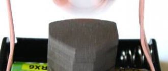
The enameled wires should be wound around the battery, creating a small circle that will serve as the motor winding. Then, with the ends of the wire, wrap the winding so that it does not develop.
To get the impeller ready, you must still remove the insulating enamel from the ends of the wire that will serve as the axle. Additionally, one of them will also be a primitive switch. Therefore, if on the one hand we remove all the enamel, on the other hand we must do it only on one side, top or bottom:
The easiest way to do this is to place the straightened end of the wire on flat air, such as a countertop, and then scrape away the enamel on top using a razor blade. I remind you that the other end must be insulated around the perimeter!
Finally, straighten the axle so that the impeller is as balanced as possible.
Then make two small hoops (bearings) in which the rotor will spin. The diameter of the rim should be about 3mm (it is best to use a winding nail).
Pieces of wire with bearings must be soldered to the battery. Then we will glue it together into a small magnet so that one of its poles points upward. It should all look something like this:
If you now turn on the rotor, it should rotate at high speed around its axis
Sometimes a little pre-start is required by gently turning the rotor until it "snaps" into place. This model of the electric motor performed during this action can be seen in the video:
We can also make a more durable version of this physical toy. I used a large magnet from an old speaker that I attached to a universal circuit board with wire scraps. Also, more rigid brackets are soldered to it. The 4.5V coin cell battery sits underneath the plate, and also underneath that are the cables that provide voltage to the brackets. The jumper visible on the right side functions as a switch. The design looks like this:
The work of this model is also depicted in the video.
How and why does it work?
The whole joke is based on the use of electrodynamic force. This force acts on every conductor through which electric current flows when placed in a magnetic field. Its action is described in the left-hand rule.
When current passes through a coil, an electrodynamic force is exerted on it because it is in the magnetic field created by a permanent magnet. This force causes the coil to rotate until the current is interrupted. This is due to the fact that one of the axes through which the current is supplied is isolated only along half the perimeter. Although the force is no longer working, the coil performs the second half of the rotation due to its inertia. This continues until the axis turns into its isolated side. The circuit will be closed and the cycle will repeat.
The presented electric motor is a simple but effective physical toy. The lack of any sensible practical applications makes the game very enjoyable.
Have fun and informative entertainment!
Learning to create a gasoline outboard motor
This product is more profitable because it has increased power. It guarantees an increase in speed, which means covering a larger area to select a good place for fishing.
- The power is always at the same level, which cannot be said about the electric motor, which has many disadvantages and the battery takes up useful space.
- It is allowed to use a unit from a trimmer, chainsaw, walk-behind tractor and other gasoline-based products. The choice depends on the boat, available mounts and financial capabilities.
- A trimmer is considered the best option, since minor modifications are required. You will have to replace the line securing device and add a propeller. And the entire engine can be used on a boat.
- In other cases, you will have to add a gearbox, propeller, shaft and make other modifications. And the process of connecting such a system, taking into account reliable operation, is not characterized by simplified actions. More serious skills are required compared to assembling and configuring an electric drive.
But this does not mean that there is no alternative. Particularly advanced fishermen have learned to use a motor cultivator. To do this, they get rid of the cutter and replace this unit with propeller blades.
In both cases considered, it is necessary to take into account that you will still have to think through the process of installing the engine on the boat. This is especially difficult in the case of an inflatable or rubber product.
How to Make a Simple Stirling Engine (with Photos and Video)
Let's make a Stirling engine.
A Stirling engine is a heat engine that operates by cyclically compressing and expanding air or other gas (working fluid) at various temperatures so that there is a net conversion of thermal energy into mechanical work. More specifically, the Stirling engine is a closed-cycle regenerative thermal engine with a continuously gaseous working fluid.
Stirling engines have higher efficiency than steam engines and can reach 50% efficiency. They are also capable of operating silently and can use almost any heat source. The thermal energy source is generated externally to the Stirling engine rather than through internal combustion as is the case with Otto cycle or diesel cycle engines.
Stirling engines are compatible with alternative and renewable energy sources as these may become increasingly important as the price of traditional fuels rises and in light of issues such as oil depletion and climate change.
In this project we will give you simple instructions on how to build a very simple motor
DIY
Stirling using a test tube and syringe
.
How to make a simple Stirling engine – Video
Components and Steps to Make a Stirling Motor
1. A piece of hardwood or plywood
This is the basis for your engine. Thus, it must be rigid enough to cope with the movements of the engine. Then make three small holes as shown in the picture. You can also use plywood, wood, etc.
2. Marble or glass balls
In the Stirling engine, these balls perform an important function. In this project, the marble acts as a displacer of hot air from the warm side of the test tube to the cold side. When marble displaces hot air, it cools.