A huge number of electrical appliances used in everyday life and industry base their operation on determining the level of ambient temperature. The measuring element in them is a temperature sensor that is triggered when heated or cooled to a set level. They can be purchased in most stores; they are included with ovens, controllers and other devices, but it is much more interesting to make a thermostat with your own hands.
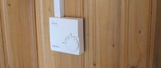
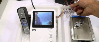
Example of a simple thermostat
Next, we will look at the principle of operation and options for making such a homemade product.
Mandatory thermostat composition
Each thermostat necessarily contains the following modules:
- Measuring unit (temperature sensor); logical block (comparison block); executive unit (electronic or electromechanical switch);
- The operation of the thermostat can be described as follows: the logical unit compares the temperature with the set one, and based on the comparison results, issues a command to the executive unit to turn on or off the heater (cooler).
- Many temperature sensors are a measuring bridge (usually resistive). Such a bridge consists of four resistances, of which three resistors have a constant resistance, and one resistor changes resistance depending on temperature.
Having carefully studied the circuit for connecting resistors to form a logic (comparison) block, you can pay attention to the fact that the resistances of the resistors (all but one) are constant, while the resistance of one resistor varies depending on the temperature, this resistor serves as a sensor that measures the temperature environment, and the remaining resistors are elements of the unit for comparing the temperature with the set one.
When the sensor resistance changes, a potential will appear on one of the diagonals of the circuit, which can be used to control the thermostat actuator.
Usually, for the final comparison of the resistance of the temperature sensor with the resistance specified by the controller, a comparator microcircuit is used, which is the logical block of the thermostat.
- When a certain (set) temperature is reached, voltage appears at the comparator terminals, which can be used to further control the actuator, and it, in turn, will turn on or off the heating element (or cooler).
- Thus, various devices operate that require monitoring the temperature of an object. This could be an electric heating system, a water heater, an incubator or heated floor, a soldering station, or an engine cooling system. Control of furnaces or refrigeration equipment.
- As can be seen from this listing, temperature control devices can be used in a wide variety of areas.
Depending on how exactly the temperature is regulated, thermostats are usually distinguished according to the principle of their operation, namely, electromechanical and electronic; electronic devices can be distinguished as digital devices.
The work of the first two types consists of triggering the actuator when the object reaches a given temperature, and in digital devices, the signal from the sensor can be pre-processed, which is why such devices are most often used in PID control devices.
Temperature hysteresis
Any regulator has tolerances for switching to temperature conditions laid down by the manufacturer. All that remains is to select the heating range.
If you set the room temperature to +20°C, and the hysteresis (lag) of the temperature sensor is 2 degrees, then automatic switching on will be at +18°C and switching off at +22°C. The room cools down gradually. When the temperature drops to the set hysteresis settings, indoor air heating is turned on.
The set temperature and the speed at which it is reached depend on many factors. Four of them are the main ones:
- coolant supply temperature;
- radiator material (cast iron, aluminum);
- concrete depth and pipe distance (for heated floors);
- heat loss - if the window is open or the room is poorly insulated, you will wait a long time for the desired temperature.
This is why hysteresis is so important. It evaluates the above aspects and gives a signal to turn on/off individually for each room. The specified allowances in the temperature mode allow you to correctly set the temperature for a comfortable feeling and avoid unnecessary energy costs.
Features of thermostat circuits
In thermostats, the actuator can be an electromechanical relay; in cases where the actuator is powered by alternating voltage, a thyristor can easily be used as an actuator.
- The undoubted advantage of using a thyristor over an electromagnetic relay is that it has no mechanical contacts, and this has a very positive effect on the service life of this element (especially when controlling powerful loads).
- The main advantage of the relay is the low voltage drop across its contacts when on. And this, in turn, significantly reduces its heating compared to a thyristor.
The comparator can be either a specialized microcircuit or a conventional operational amplifier microcircuit.
Concept of temperature controllers
Products in this category are used to solve various problems. Based on the appropriate temperature threshold setting, power is supplied (turned off):
- heating in the cellar;
- heating the soldering station;
- boiler circulation pump.
From the examples given, the basic requirements for accuracy that a suitable thermostat circuit must provide are clear. In some situations it is necessary to maintain a given level no lower than ±1C°. To monitor operating parameters, an operational indication is needed. Load capacity is essential.
The listed features explain the purpose of typical functional units:
- the temperature value is recorded with a specialized sensor (resistor, thermocouple);
- the readings are analyzed by a microcontroller or other device;
- the actuator signal is sent to an electronic (mechanical) switch.
For your information. In addition to the parts discussed, the thermal relay circuit may contain additional components to supply power to an electric heater or other powerful load.
Thermostat microcircuit
The modern level of integration of electronic devices makes it possible to design this device in a single microcircuit; such microcircuits can often be found in a wide variety of household and industrial devices.
However, when such a microcircuit fails, there is often simply nothing to replace it with. Therefore, in order to repair a thermostat, often, instead of such a microcircuit, a homemade thermostat assembled on separate elements is used.
Of course, such a device is much larger than a microcircuit, however, if the dimensions of the device allow, then the use of such a device can be completely justified.
Example of a thermostat
The thermostat can be made from parts that are not in short supply. They can be easily purchased in most cities.
The thermostat circuit is shown in the figure; it is a simple thermostat.
- To power the device, a source based on a step-down transformer is used as a diode bridge; low-power diodes suitable for reverse voltage are used, for example, 1N4007.
- An electrolytic capacitor is used as a smoothing filter, and an integrated voltage stabilizer is used in the power supply, with an output voltage of five volts.
- A medium power transistor with direct conduction is also used, for example, it could be a KT816A transistor. Also, the circuit uses the so-called controlled zener diode TL431.
- Constant resistance resistors with ratings 4.7; 160, 150 and 910 kilo Ohm. And a variable resistance of 150 kilo ohms. A 50 kilo ohm thermistor was used as a temperature sensor.
The characteristic of this resistance (positive or negative) depends on what load the thermostat will control (heater or refrigerator).
An LED is used as an indicator of the operation of the device, and an electromagnetic relay with an operating voltage of twelve volts (for example, a car) is used as a switching element.
A fixed switch for sufficient current and a housing with a volume sufficient to accommodate the device are also used. Also, for ease of installation, it is recommended to make a printed circuit board according to the diagram of the device being manufactured.
How to do it?
Instructions for making a thermostat with your own hands are based on strict adherence to the chosen scheme, according to which it is necessary to connect all the components into a single whole. For example, an electronic circuit for an incubator is assembled using the following algorithm:
- Study the image (it’s better to print it out and put it in front of you).
- Find the necessary parts, including the case and board (old ones from the meter will do).
- Start with the “heart” - the K140UD7/8 integrated amplifier, connecting it with a positively charged reverse action, which will give it the functions of a comparator.
- Connect the negative resistor MMT-4 in place of “R5”.
- Connect the remote sensor using shielded wiring, and the cord length can be no more than a meter.
- To control the load, include thyristor VS1 in the circuit, installing it on a small radiator to ensure adequate heat transfer.
- Set up the remaining elements of the circuit.
- Connect to the power supply.
- Check functionality.
By the way, by adding a temperature sensor, the assembled device can be safely used not only for incubators, drying, but also for maintaining the thermal regime in an aquarium or terrarium.
Sequence of work
Having mounted the circuit in the chosen way, you should install the sensor in such a way that, during operation, it controls the temperature of the required object.
- The variable resistor should be installed in such a way that it can be easily accessed.
- After that, you need to put a scale of set temperatures that will be maintained by the thermostat.
After all this work has been completed, connect the power cord to the device (if you do this earlier, it will greatly interfere with operation).
After assembling and configuring the device, it is placed in the housing.
Required materials and tools
In some situations, you will need the skills to make a complex printed circuit board. The simplest circuits are assembled in a few minutes using a soldering iron and surface-mounting technology. Before performing work operations, you must purchase:
- components;
- Consumables;
- measuring equipment.
The shopping list is compiled based on the selected electrical circuit. To protect the device from adverse external influences and improve its appearance, an appropriate housing is created.