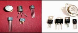
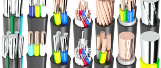
Types of cables for connection
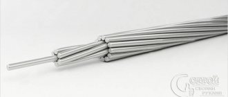
The most common cable for home electrical wiring is a PVA connecting cable, consisting of two insulating layers. Copper strands, stranded, twisted along the central axis. The wire is flexible, making it great for a variety of connections.
The voltage of connected devices must be up to 380 Volts.
The cross section is selected depending on the load:
- for a current of 6 A, PVA with a cross section of 0.75 mm is used;
- for 10 Amperes - the cross-section is 1 mm;
- for currents of 16 A – 1.5 mm.
In addition to the PVS wire, for connection there are multi-core cables ShVVP, PUGNP, PRS, KG. They are used less frequently for home wiring than PVS.
Installation of a block of several sockets
Single sockets and industrially manufactured multi-socket units are available with a rating of 10 or 16 A. Consequently, self-assembled blocks of several sockets are designed for the same currents.
The power lines of the electrical wiring for the group of sockets are arranged from a conductor with a cross-section of 2.5 mm2 and are connected on the panel through a circuit breaker with a rating of no more than 16 A.
A single 10 A socket can be used to connect equipment with a power of up to 2.2 kW, and a 16 A socket with a power of 3.5 kW. The total power of devices connected to the socket blocks should also not exceed these values.
The number of sockets in a self-installed unit is determined based on reasonable needs, with reference to restrictions on the duration of permissible currents. The minimum required number of consumers connected to the unit and their total power are calculated. If the obtained value is outside the acceptable range for the existing wiring, it is necessary to reduce the number of sockets in the block and compensate for this by laying additional socket lines.
Having calculated the required number of sockets in the assembly, choose the design of the block:
- invoice - located on the wall surface with preliminary installation of a flat socket box;
- built-in - installed in a module made of mounting boxes, for which a mounting socket is made in the wall.
Installing a surface-mounted socket block
Outdoor units are a collapsible box made of flame-retardant PVC plastic, in which 4-6 sockets are arranged in standard seats.
The front part of the box is attached to its base using latches and does not require special tools for removal. On the base of the box there are holes with a diameter of 20-32 mm, equipped with easily removable plugs for introducing cables into the box.
The cables are run into the box, after which it is applied to the wall and aligned horizontally, after which markings are made for drilling holes for fastening with self-tapping screws.
Once the box is attached, the front covers are removed from the sockets, in which holes for the wires to enter are cut out on the desired side with a knife, and the contacts are connected with jumpers.
The cross-section of the jumper wires must be no less than the cross-section of the incoming cable.
The installation of the grounding line must be carried out in strict accordance with the requirements of the PUE - the PE cable must be solid and reach the most distant outlet, having branches along the way separately for each point.
The connection of each open conductive part of the electrical installation to the neutral protective or protective grounding conductor must be made using a separate branch.
The series connection of exposed conductive parts into the protective conductor is not permitted.
Depending on the model, such multi-outlet blocks provide 1-2 seats designed to install sockets for a wired Internet connection or a landline telephone. Before installation, special landing supports are additionally inserted into these sockets. Partitions are provided in the cover of the box to separate the power wiring from the data cable.
GOST classifications and requirements
Wire connectors are any devices that serve to close/open an electrical circuit. These can be electrical installation products - sockets, switches, as well as metal bars and plates, lugs, terminals and terminal blocks - blocks with several sockets.
We will focus on connectors in a narrower sense - on elements that create detachable and non-separable connections and ensure their reliability and functionality - that is, on all kinds of terminals, terminal blocks and sleeves.
The simplest example of a lug for a stranded wire. The terminal is a metal sleeve-tube fixed at the end of the conductor using crimping pliers
Terminals are called both metal elements for decorating the ends of single- and multi-core wires, and small plates inside connecting devices - sockets, terminal blocks, patch panels.
The terminals differ in material, shape and size, but are similar in purpose - they provide mechanically strong switching of two or more wires, without electrical losses and installation difficulties
The classification of electrical connectors is presented in GOST 10434-82 , which provides information on the division into classes (1, 2, 3) and groups (A, B). Also, according to standards, contact connections are divided into detachable and permanent, requiring stabilization or working without it.
Some recommendations may be useful not only to professionals, but also to home craftsmen who install their own electrical wiring.
For example, it talks about the most preferred methods of connecting aluminum plates - soldering or welding and aluminum tips - crimping or welding.
What is the best way to reliably connect two cables together?
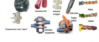
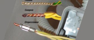
Methods of connecting cables that require equipment and skills in the field of electrical engineering:
- soldering;
- welding;
- crimping with sleeves.
Simple connection methods that do not require tools or knowledge:
- connection using terminal blocks;
- spring clamps;
- PPE caps;
- bolted connection.
The choice of connection method depends on the characteristics of the wires. It is necessary to take into account the type and material of the core, the number of wires, and operating conditions.
Aluminum
Aluminum wires can also be connected using any method, but with some special features. When connecting, the metal must be manually stripped of insulation.
Copper and aluminum wires cannot be connected directly. The connection point becomes very hot and over time the contact weakens. Therefore, it is better to use terminal blocks, wago, bolt connection or special branch clamps.
Copper
Copper wire can be connected using terminal blocks, Wago clamps (necessarily using special paste), using a bolt, or soldering.
Connecting electrical wires by twisting
Until recently, twisting was the most common method of connecting wires when doing electrical wiring; due to its accessibility, all it took was a knife and pliers. But, according to statistics, twisting is an unreliable way to connect conductors.
According to the electrical installation rules (PUE), twisted connections when installing electrical wiring are prohibited. But, despite the noted disadvantages, the twisting method is currently widely used. Connecting conductors of low-current circuits by twisting, subject to certain rules, is quite justified.
The photo on the left shows how twisting is unacceptable. If one conductor is twisted around another, the mechanical strength of such a connection will be insufficient. When twisting wires, you must make at least three turns of wires around each other. In the middle photo, the twisting is done correctly, but a copper conductor is twisted with an aluminum one, which is not permissible, since when copper comes into contact with aluminum, an emf of more than 0.6 mV occurs.
In the photo on the right, the twisting of copper and aluminum wires is done correctly, since the copper wire is tinned with solder before twisting. You can twist several wires together at once; in a junction box, sometimes up to 6 conductors are twisted, wires of different diameters and from different metals, a stranded wire with a single-core wire. Only the stranded wire needs to be made single-core by first soldering it with solder.
What is wire twisting and why is it dangerous?
Several decades ago, when the load on electrical wiring was not so great, such a connection was popular. Moreover, experienced craftsmen taught me, then a young electrician, to first thoroughly strip the metal cores, twist them tightly, and crimp them with pliers.
The length of this twist had to be created on the order of 10 cm to ensure good electrical contact, as shown in the lowest example. And they would reject anything higher, despite its beauty.
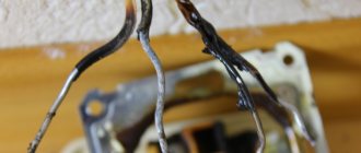
Inside closed, dry rooms, such twists worked for years and decades. However, many electricians violated the technology and created poor-quality contact.
In addition, in a humid environment, the metal oxidizes. The electrical resistance of its transition surface layer deteriorates. This leads to increased heating of the cores and premature damage to the insulation.
Therefore, modern rules, in particular the PUE, prohibit simple twisting of wires, no matter how beautifully and reliably it is done.
Particularly dangerous are twists of aluminum wires, as well as cores made of different metals - copper and aluminum.
This is due to the high ductility of soft aluminum and its high ability to create, under the influence of atmospheric oxygen, an outer layer of oxides that protects the internal structure of the metal. This film reduces conductivity.
When currents flow with increased loads, aluminum, which has a high coefficient of linear expansion, heats up, increasing its volume. After cooling, it contracts, breaking the tightness of the joint.
Each heating and cooling cycle degrades the electrical performance of the strand. In addition, copper and aluminum work as a galvanic couple, and these are additional chemical reactions with the formation of surface oxides.
Recommendation: wherever you find a simple twist, get rid of it. Reinforce it by soldering, welding, crimping or any other approved method.
Old and modern device standards
As equipment has improved, the way phones connect to the communications network has undergone a number of changes. In the first models of telephones, connection to the communication line was carried out without the use of sockets at all.
To create a closed current loop, the wires were simply twisted together or connected by any other available means.
In the 80s of the last century, connections between telephone exchange lines were made using two-core copper wires. And to ensure a quick-disconnect connection to the telephone, sockets and plugs of the RTShK-4 standard were used. This abbreviation stands for "four pin telephone socket."
The RTShK-4 design includes a key and two pairs of contacts. The first pair ensures the phone operates in normal mode, the second pair allows you to connect an additional line, provided that both devices are on the same phone number.
As a result of the widespread dissemination of microprocessor technologies, Registered Jack equipment marked “RJ” began to be actively used to replace obsolete models of the RTShK-4 standard. It complies with the international standard IEC 60884-1 and 60669-1.
Connection of modern landline telephone models for use at the household level is carried out through sockets equipped with one pair of contacts. The housings of such devices are mounted in the cavity of a plastic module and are marked with RJ-11 symbols.
Between the two contacts, which are compact metal plugs, the cores of the supply wire are buried. Models of the RJ-11 standard are recommended for connecting devices to linear telephone lines.
To connect two devices to separate lines and create office mini-PBXs, RJ-12 and RJ-14 standard devices are used. Universal four-wire connectors are suitable for most models of telephone equipment.
To connect several devices at once, you just need to assemble the sockets sequentially into blocks, while observing the diagram: the first line is connected to contacts No. 2 and No. 3, and the second - to No. 1 and No. 4. Devices of this series are mostly used to create mini-PBXs when arranging office premises.
Installing an adapter allows you to connect plugs of both old and new standards with lines equipped with modern technologies.
The main difference between RJ-25 standard devices is three pairs of working contacts. For this reason, the connection of such equipment can only be carried out by a qualified specialist who is well versed in telephony and electrical issues.
When connecting computer systems, faxes, modems and other complex communication devices, the RJ-45 standard is also used. When connecting RJ-45 devices, the main attention is paid to the matching of the plastic keys.
Despite the design differences between the old and new standards, the device plugs have similar connectors and dimensions. The device is connected to the network only through two contacts. Only modern models use only middle contacts.
For those wishing to familiarize themselves with the connection features, the photo gallery will help:
Connecting electrical wires by soldering
The connection of copper wires with high-quality soldering is the most reliable and is practically not inferior to a solid wire. All of the above examples of twisted wires, except for aluminum and tinsel, when tinning the conductors before twisting and then soldering them with solder, will be reliable on a par with solid wires. The only drawback is the extra labor involved, but it's worth it.
If you need to connect a pair of wires and the twisted conductors must be directed in different directions, then a slightly different type of twist is used.
By splicing two pairs of double wires in the manner described below, it is possible to obtain a compact and beautiful connection by twisting both single-core and stranded pairs of conductors. This twisting method can be successfully used, for example, when splicing broken wires in a wall, extending a wire when moving a socket or switch from one place on the wall to another, when repairing or extending the length of a carrying cable.
To obtain a reliable and beautiful connection, it is necessary to adjust the lengths of the ends of the conductors with a shift of 2-3 cm.
Remove the insulation from the ends of the wires.
Twist the conductors in pairs. With this type of twisting, two turns are enough for a single-core wire, and five for a multi-core wire.
If you plan to hide the twists under plaster or in another inaccessible place, then the twists must be soldered. After soldering, you need to go over the solder with sandpaper to remove any sharp solder icicles that could pierce the insulation and stick out from it. You can do without soldering if the connection is accessible and there is a small current flowing through the conductors, but the durability of the connection without soldering will be much lower.
Due to the shift of the twisting points, there is no need to insulate each of the connections separately. We attach a strip of insulating tape on both sides along the conductors. Finally, you need to wind three more layers of insulating tape. According to the requirements of the Electrical Safety Rules, there must be at least three layers.
Wires spliced and soldered in the manner described above can be safely laid in the wall and plastered on top. Before installation, it is advisable to protect the connection with a vinyl chloride tube placed in advance on one of the pairs of wires. I have done this many times, and the reliability has been confirmed by time.
How the telephone is connected directly to the communication line conductors
In some situations, it becomes necessary to connect a telephone set to a communication line, but the required outlet is not available or it is not suitable at all. In this case, it is possible to connect the telephone wire directly to the communication line conductors by ordinary twisting. Bare areas are usually covered with ordinary electrical tape. The quality of communication with this connection method will not suffer in any way.
The telephone cord is characterized by a high degree of flexibility - it is presented in the form of a special wire with cores made using special technology. Thus, ultra-thin copper ribbons are wound over a cotton thread, and the conductors themselves are called tinsel. Such conductors are widely used in the production of headphones, when connecting telephone handsets to basic devices, as well as for devices whose operation requires frequent or constant bending of the wire.
In each core of tinsel-type conductors, there are several at once; they are intertwined with each other, and therefore it is quite difficult to solder them due to the low mechanical strength of such a connection. The most reliable way is twisting. It is performed according to the following algorithm:
- The tinsel of the telephone cord is freed from insulation at a distance of 10-15mm, and the conductors of the line wire - 20-25mm. You can use a regular knife for this.
- Both wires should be folded together, while the tinsel should be bent towards the conductor, and the core of the linear wire should be wound onto the tinsel, pressed against the insulating layer. The optimal number of turns is up to 5 pieces.
- The second conductor of the cord is twisted in the same way.
- The connection point is covered with insulating tape.
This connection is as neat as possible. It can also be straight - to do this, before applying the insulation, the linear wire should be bent 180 degrees. At the same time, the mechanical strength of the entire connection increases significantly.
How to repair a telephone line
If for some reason the connection is interrupted and the landline telephone does not work, you can call a signalman, who, as a rule, comes at an inconvenient time, or restore the connection yourself. The phone may stop working for two reasons:
- Due to a breakdown of the telephone;
- Due to a problem with the telephone line.
In the first case, you can solve the problem by simply connecting a spare phone instead of the damaged one. If the connection is restored, then it was the device that was faulty, and if not, then the line.
Whether the line is working or not can be checked by measuring the voltage at the telephone socket. If you don't have a tester on hand, it's a good idea to check to see if the line wire is securely connected to the outlet terminals. If the connection is present and it is completely reliable, then it is very easy to determine which contacts your communication line is connected to. If this is not possible, you can check the reliability of the connection to the plinth by examining all the connected lines.
In the case when there is voltage at the contacts of the plinth, and your pair of conductors is securely connected, this indicates that the conductor that goes to the point where the telephone is installed is broken. If there is no voltage, it is recommended to disconnect any conductor that goes into the apartment, and after a certain period of time, repeat the measurement. If voltage appears, this indicates that there may be a short circuit in the wire that goes from the plinth to the outlet in the house. You can check this fact by reconnecting the telephone line wire to the contacts - when measuring the voltage, it will disappear again.
Connecting a telephone extension cable
In some situations, you need to move the telephone set to another location, but the length of the cord does not allow this, and dismantling and installing the socket in the right place is not always possible. In addition, unplanned repairs and sealing of the former installation site are not entirely pleasant activities. The issue can be resolved using a regular telephone extension cord. You can buy it or make it yourself using the desired type of plug, socket and a piece of any cable.
If you do not have a socket and plug, the standard wire can be extended/increased by constructing an insert of a double conductor or two single conductors twisted together on any section of the wire. The insert can be made from wire with any cross-section, both single-core and stranded. The standard wire is cut at a distance of 12-15 cm from the plug into two parts. To connect the ends of the conductors, the technology described above is used. If a thin stranded wire or a thick single-core wire is used for insertion, then the tinsel is not bent, but folded parallel to the stripped conductor, after which this place is wrapped with a wire with a diameter of no more than 0.5 mm.
It should be noted that in the production of modern telephone cords, it is not tinsel that is used, but ordinary stranded wire with a fairly small cross-section. Due to their thinness, such conductors are connected using a slightly different technology:
- The insulating layer is removed from the conductor with a shift.
- Next, the wires should be tinned, with a thinner wire wound around a thicker one.
- Simple twisting is performed if the conductors have approximately the same diameter.
- The twisting area is soldered with solder.
- The resulting connection is isolated.
The second pair of conductors is connected in a similar way.
Terminals
Terminal blocks for connecting wires provide one undeniable advantage: they can connect cores of different metals. Both here and in other articles, we have repeatedly reminded that twisting aluminum and copper wires together is prohibited. The resulting galvanic couple will result in corrosion processes and destruction of the connection. And it doesn’t matter how much current flows at the connection. Late or early, the twist will still start to heat up. Terminals are the way out of this situation.
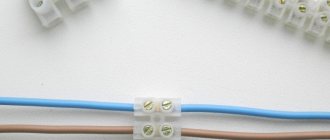
Terminal block
The simplest and cheapest solution is polyethylene terminal blocks. They are not very expensive and are sold in every electrical goods store.
The polyethylene frame is designed for several cells, inside each there is a brass tube (sleeve). The ends of the connected wires must be inserted into this sleeve and clamped with two screws. It is very convenient that as many cells are cut from the block as it is necessary to connect pairs of wires, for example, in one junction box.
But not everything is so smooth, there are also disadvantages. At room conditions, aluminum begins to flow under screw pressure. You will have to periodically inspect the terminal blocks and tighten the contacts where the aluminum conductors are fixed. If this is not done in a timely manner, the aluminum core in the terminal block will become loose, lose reliable contact, and, as a result, spark and heat up, which can result in a fire. Such problems do not arise with copper conductors, but it would not be superfluous to periodically inspect their contacts.
Terminal blocks are not intended for connecting stranded wires. If stranded wires are clamped into such connecting terminals, then when tightening the screw under pressure, the thin wires may partially break, which will lead to overheating.
In cases where it becomes necessary to clamp stranded wires into a terminal block, it is imperative to use auxiliary pin lugs. It is very important to choose the correct diameter so that the wire does not jump out later. The stranded wire must be inserted into the lug, crimped using pliers and secured in the terminal block.
As a result of all of the above, the terminal block is an ideal option for single-core copper wires. With aluminum and stranded ones you will have to comply with a number of additional measures and requirements.
How to use terminal blocks is shown in this video:
Terminals on plastic blocks
Another very convenient wire connector is a terminal on plastic blocks. This option differs from terminal blocks in that it has a smooth metal clamp. The clamping surface has a recess for the wire, so there is no pressure on the wire from the screw being tightened. Therefore, such terminals are suitable for connecting any wires.
Everything about these clamps is extremely simple. The ends of the wires are stripped and placed between the contact and pressure plates.
Such terminals are additionally equipped with a transparent plastic cover, which can be removed if necessary.
Self-clamping terminals
Wiring installation using such terminals is simple and quick.
The wire must be inserted into the hole to the very end. There it is automatically fixed using a pressure plate, which presses the wire to the tinned busbar. Thanks to the material from which the pressure plate is made, the clamping force does not weaken and is maintained all the time.
The internal tinned busbar is made in the form of a copper plate. Both copper and aluminum wires can be fixed in self-clamping terminals. These terminals are disposable.
And if you want clamps for connecting reusable wires, then use terminal blocks with levers. They lifted the lever and inserted the wire into the hole, then fixed it there by pressing it back. If necessary, the lever rises again and the wire protrudes.
Try to choose clamps from a manufacturer that has proven itself well. The clamps have especially positive characteristics and reviews.
The advantages and disadvantages are described in this video:
PPE caps – connecting insulating clips
Now let’s look at the PPE spring caps in detail. These clamps have not gained such great popularity among electricians and ordinary people, and there are reasons for this.
Terminal clamp
This device will not be a block, but depending on the model, it can connect up to 8 conductors in one housing.
The outer material is plastic, which has a number of features:
- Does not support combustion even when exposed to open fire;
- Has a high melting point;
- Withstands voltages from 300 to 600 V, which indicates high insulating properties;
- It has high mechanical strength and reliably protects the connection from any damage.
The cap has a cone shape. The outside is corrugated or has two blades for ease of use.
A compression spring of the same shape is installed inside. As was written above, its edges are sharpened in a special way, which allows you to securely fix cores of different sizes.
If we compare PPE with Vago terminals, they will have a couple of obvious disadvantages:
- Inability to simultaneously connect aluminum and copper wires.
- Complicated installation that requires special processing of the wires - it is necessary to thoroughly clean the insulation without protruding even a millimeter of the bare part of the wire beyond the cap body.
- An accurate selection of the cap model for the wire cross-section is required, since the best contact will be in the narrowest place, and if the wires are too thin, there will be increased resistance at the connection point, as when twisting the wires.
- Sufficient force is required to ensure good contact between the conductors.
- The cores must be strictly the same diameter.
- For multi-core wires, this solution will not be the best, since partial damage to thin wires is possible.
PPE caps in the junction box
The cap is installed in the following sequence:
- The wires are exposed from insulation to a length corresponding to the length of the corrugation on the cap;
- Their ends are connected in parallel, without preliminary twisting.
- The cap is placed on top and rotated with force clockwise.
- When connecting three wires, a preliminary twist is made, after which its tip is bitten off.
How PPE works
The following video will show how to install PPE caps.
There are five types of PPE terminals in total, the difference between which can be seen in the following image.
The difference between PPE caps
Interesting to know! PPE 5 can be used to connect 8 cores with a cross section of 2.5 mm2.
The table also shows the color coding of the models. The majority of manufacturers adhere to it, but there is no single standard, so there may be differences, so be careful when purchasing.
Pay attention to the product labeling (PPE 1 1.0-3.0 and similar). It will help you accurately select the product for the cross-section of your wire.
The first digit of the marking indicates the type of housing, the rest indicate the permissible range of cross-sections.
How to connect a telephone socket
When installing a telephone socket, it should be taken into account that the voltage for low-current communication devices does not exceed 60 Volts. But even reduced voltage can still create a current, causing discomfort to a person.
At the moment when a call occurs over the telephone line, the voltage completely rises to 110-120 Volts. And it can cause serious pain upon contact. It drops to a value of 12 Volts only after removing the handset.
The principle of placement and method of installing telephone sockets is practically no different from the technology for installing electrical sockets. Since today the most common devices are those that have the J-11 and J-12 standards, we will consider the intricacies of connecting a telephone jack using their example.
Stage #1: Preparatory work
The first thing you need to do is study internal communication patterns. They are included with the product instructions.
There should be no problems when connecting the J-11 and J-12 standards: you just need to connect the wires of the appropriate polarity. The main thing is that in the plug suitable for the device, the wires are routed in a mirror image of the contacts of the socket.
If you unknowingly purchased and plan to install the J-25 standard, the design of which involves 6 contacts, use only the 3rd and 4th contacts for connection.
When planning to use an old standard device, you should worry about purchasing a universal socket in advance. It is equipped with a four-pin connector and connector. In addition to the socket itself, it is also necessary to prepare a two-core wire with a cross-section of 0.3-0.5 mm.
It is necessary to determine and mark the installation location and height in advance.
The following tools need to be prepared for the work:
- building level;
- cross knife;
- voltmeter;
- screwdriver;
- wire cutters;
- graphite pencil;
- protective gloves;
- Double-sided tape;
- hammer drill (if installing a new point).
When choosing a screwdriver, you are guided by the type of surface and dimensions of the screws used for fastening. To minimize the likelihood of electric shock, it is better to perform all manipulations with a screwdriver whose handle is insulated.
To connect a hidden type socket, you must first make a hole in the wall for its installation - a socket box. This can be done using a hammer drill equipped with a special crown with a diameter of 60-70 mm.
In the absence of one, the work can be done with an ordinary hammer and chisel. But manual labor will take much more time and effort. Then, to the hole made, it is necessary to drill a channel for laying the telephone cable.
There are certain nuances when installing a socket box into a plasterboard wall.
Stage #2: Stripping the ends of the cores
Before you start melting the wires, you need to strip the ends of the wires, removing the outer layer. Just expose the outermost 4 cm of the wire.
When stripping a telephone cable, remember that it is very vulnerable to damage. And broken wires will only lead to equipment malfunction. Therefore, it is important to use a specialized stripping tool.
Since it is not always possible to carry out the cutting accurately the first time, experienced craftsmen recommend that when laying the cable, make some allowance for its length. The excess wire can then be hidden under the cover of the device.
The technician’s task is to strip the ends of the wires from the braid so that when exposed they are intact and free of any defects.
Step #3: Connecting the outlet wires
Stripped wires with separated cores are connected to the connectors of the box itself, focusing on the markings indicated on the front panel of the indoor unit. With a closed installation method, for ease of connection, the wires are made to protrude beyond the wall plane by 50-80 mm.
Experts recommend checking the polarity of the contacts when connecting wires using a tester.
If the rules regarding polarity are not followed, there is a high risk that the telephone will malfunction from time to time during operation.
At this stage of work you will need a voltmeter. With its help you need to check the readiness of the communication line. The line voltage should be between 40-60 Volts.
The supplied cable cores are applied to the clamp and tightened tightly with special screws, ensuring reliable fixation. The shape of the grooves to which the cores are attached facilitates the installation process. There is no need to wrap the joints with electrical tape.
When performing open mounting, at the final stage all that remains is to close the housing cover using the latch and secure it with screws. The finished socket is attached to the wall or floor, “planting” it with double-sided tape.
With a closed installation method, making sure that the wires are not intertwined in the socket box, according to the markings applied, the indoor unit is mounted into the wall. Having given the block the desired position, the structure is fixed using expansion screws and self-tapping screws.
At the final stage, all that remains is to eliminate the gaps between the socket box and the wall, covering it with gypsum mortar, and also seal the channels with the laid telephone cable.
After the plaster has acquired the desired strength, the protective edging is installed in place and the front panel is attached. In modern devices, the protective edging is snapped onto the internal unit, and the front panel is secured by screwing in screws.
If you need to connect a multi-socket outlet that allows you to install several telephone sets, you must adhere to the same technology as when installing the classic version of the device. The only difference in the process is the increase in the number of conductors requiring connection.
Scotch-lock
Couplings of this type are for one-time use. Used for wires with low operating currents (telephone lines or wires for low-power LED lamps).
These clamping couplings make connections by means of a mortise contact. The wires don't even need to be stripped before connecting. They are inserted directly into the insulating layer into adhesive tape and crimped with pliers. The plate, which has cutting contacts, cuts into the insulating layer, due to which contact between the cores occurs.
In addition to the fact that stripping of cores is not required, adhesive locks have a number of other advantages:
- low cost;
- versatility;
- no special devices are needed, crimping is done with ordinary pliers;
- waterproof (there is a hydrophobic gel inside the coupling, which protects the contact connection from moisture and corrosion).
- If the Scotch-lock coupling needs to be replaced, it is simply cut out and a new one is installed in its place.
What are distribution boxes for?
There are many factors that speak in favor of the existence of junction boxes:
- The power system can be repaired in a matter of hours. All connections are accessible, you can easily find the area where the wires have burned out. If the cable was laid in special channels (corrugated tube, for example), then the failed cable can be replaced in an hour;
- Connections can be inspected at any time. As a rule, wiring problems occur at the connection points. If the socket or switch does not work, but there is voltage in the network, first check the quality of the connection in the junction box;
- the highest level of fire safety is created. It is believed that dangerous places are connections. Using a box will keep them in one place.
- minimal time and financial costs when repairing wiring. There is no need to look for broken wires in the walls.
How to connect a telephone socket to a telephone cable: diagram
In this collection, we have collected all the necessary information, thanks to which it will not be difficult to crimp a twisted pair cable for one or another connection scheme with your own hands, using the necessary tools. The main thing is to adhere to the basic rules; it wouldn’t hurt to repeat them again:
Expert opinion
It-Technology, Electrical power and electronics specialist
Ask questions to the “Specialist for modernization of energy generation systems”
How to crimp a twisted pair cable: a step-by-step guide - Lifehacker We recommend preparing several connectors for this process, as practice shows, without experience, it’s easy to break the connector during the barbaric crimping process. Ask, I'm in touch!
Sleeves
When powerful clamps for several wires are needed, sleeves are used. They are a tinned copper tube or a flat tip with a hole made for fastening.
All connected wires must be inserted into the sleeve and crimped using a special crimper device (crimping pliers). This wire clamp has a number of positive aspects:
- It is very convenient to use lugs with holes when there is a need to secure wire assemblies to housings with screws.
- Crimping at the connection does not increase the resistance.
As you can see, there are a lot of wire clamps, each with its own advantages and disadvantages. Choose based on which wires you need to connect and where the connection will be located. But do not forget that the most important thing in electricity is reliability and safety.
How to connect a telephone cable if it is broken?
Every home handyman should know how to connect a telephone cable. Such a need may arise at any time, for example, if the cable suddenly breaks or if the telephone socket has to be moved to another location, and the cable needs to be slightly extended.
In order to connect the telephone cable, you will need wire cutters, electrical tape and rubber gloves. Successful completion of the job depends on strict adherence to some simple recommendations.
If there is a parallel telephone in the house that remains in the network after a cable break, it is necessary to remove the handset from it to avoid shock from the ringing signal voltage. If all the devices fail at the same time or only one telephone is connected to the line, for safety reasons it is imperative to carry out the work with rubber gloves.
You need to find the place where the telephone cable broke. If the damaged area cannot be identified visually, you can use a special device, the so-called non-contact damage detector. If the device is missing, in the area where damage is possible, the telephone cable is completely replaced.
If the telephone cable is a so-called “noodle”, that is, a two-wire flat cable, to splice it, the cable is bifurcated so that the cut line is exactly in the middle. The ends are carefully cleaned.
The wires of one end of the cable are connected to the wires of the other end of the cable. The connections must be carefully insulated, and you must also make sure that telephones that have failed are working again.
If a telephone cable that has a new design is being repaired, the outer sheath of the cable is removed without the risk of damaging the insulation of the conductors. The two-wire cable is spliced in the same way as the TRP cable. If the cable is four-wire, it is important to connect the cores located in the middle. It is not necessary to touch the outermost veins, since they are not involved.
In case of failure of a telephone set designed to work with several lines, the outer wires must also be correctly connected, splicing together conductors of the same colors.
This completes the work of connecting the telephone cable. After making sure that all phones are functioning, do not forget to hang up on the phone you removed from when starting work.
Spring clamps for connecting wires
One of the most controversial ways to connect wires is using spring clamps. There are several types, but the two most common are wago terminal blocks and PPE caps. Externally and in terms of installation method, they are very different, but both designs are based on a spring, which creates strong contact with the wire.
There is controversy about this spring. Opponents of using wago say that the spring will weaken over time, the contact will become worse, the connection will begin to heat up more and more, which, again, leads to an even more rapid decrease in the degree of elasticity of the spring. After some time, the temperature may rise so much that the body (plastic) will melt, but what can happen next is known.
Spring clamps for electrical wiring - popular connections for wires
In defense of using spring clamps to connect wires, if they are used according to manufacturers' recommendations, problems are very, very rare. Although there are many fakes of both wago and PPE, as well as a sufficient number of photographs of them in melted form. But, at the same time, many people use them, and, under normal operating conditions, they work for years without complaints.
Types of telephone sockets
When considering different types of such devices, one of the main classifications is their division according to the installation method:
- Devices for external installation.
- Devices with internal wiring.
A secondary classification, applicable to both types, is the division of these devices according to the number of available connectors:
- Single-connector models are designed to connect 1 device and are the most popular option for installation in private homes or residential apartments.
- Multi-connector models allow you to connect several different devices at once; they are most often found in offices and office premises.
Also, on the modern market there are sockets with different connectors.
RTShK-4
This parameter is determined by the type of standard used:
- RJ-11 is one of the most common options; it implies the presence of 2 conductors in the design. Such devices are most often found and are recommended for installation if there is a line-type telephone line to which the device is connected.
- RJ-12 is less common because it is rarely used for domestic purposes. The main purpose is to connect to office mini-PBXs or a number of types of network cards.
- RJ-14 has 4 conductors and the same number of contacts. It is a universal connector designed and suitable for most modern models of telephone equipment. To connect and ensure the operation of one line, contacts 2 and 3 are used; if for some reason several lines are required, then the connection occurs through contacts 1 and 4. Surface-mounted sockets must use a green and red conductor, which are usually located in the center of the fixture.
- RJ-25 includes 3 pairs of working contacts in its design. Devices of this type are extremely complex and unsuitable for installation on your own. To carry out this process, you will need to hire a qualified specialist who understands electrical and telephony issues.
- RJ-9 is a special type of connector, the main task of which is to connect the handset directly to the device.
- RTShK 4 is a technically outdated type of sockets that were common in the USSR in the past; the design includes 4 wide contacts and a key. Designed for a specific connection option in a permanent way; for its implementation, the presence of a branch-type box is required. The presence of several telephone sockets within one room contributes to the creation of a special electrical circuit; an additional capacitor is required to complete it.
Wire Mounting Clamps
Let's move on to the second type of clamps, which are necessary when installing electrical networks. If the previously discussed options are used for switching conductors, then everything that will be presented in this chapter is used for fixing wires.
Linear tension wire clamp
All clamps that are used to secure cables and wires are divided into supporting ones (they are suspended on intermediate supports) and tension ones, which are held on anchor-type supports.
Clamps are also divided according to strength:
Clamps for linear wires are blind
- Blind - the strength of the sealing of these devices varies from 30 to 90% of the strength of aluminum wires or 10-15% of steel cables. If there is a break on one of the spans, the wire does not jump out of the clamp, but the tension from it is transferred to the support. This type is the most common when installing overhead power lines.
- Drop-out or releasing - they throw out a boat with a wire when the support garland is deflected at an angle of about 40 degrees, which ensures that there is no additional pressure on the support and a reduction in its mass. Today they are not used due to frequent cases of spontaneous ejection.
- Multi-roller - in fact, this is not quite a clamp, since the wire inside them rolls over the rollers, depending on the tension force in the adjacent spans.
- Pressed tension type clamps – This is a steel anchor in which the wire is pressed.
Wire clamp on pole
- Wedge clamp - consists of three metal parts: a base, a wedge and a pressure plate. When the wire is tensioned, it is held in place due to the high friction force. The parts wedge into each other.
In particular, the last version of the clamp can be installed with your own hands. The option shown in the photo above is used for fastening low-voltage wires and optical communication cables.
Features and connection diagram
Telephone sockets have their own individual connection features; if we talk about the modern and most common standards RJ-11 and RJ-12, they have the following connection nuances:
- The design of the device may include 2-4 contacts, which are small metal plugs. Between these elements, the cores of the supply wire must be buried.
- The telephones themselves are connected exclusively through 2 central contacts.
- To install devices with the specified standard, professional craftsmen use a special type of working tool called a cross-cutting knife. However, if you do not plan to use it frequently in the future, then you can limit yourself to a very ordinary knife with a sharpened blade. Such a tool is used to deepen the cores; when cutting through the insulating layer, contact will be ensured.
- Before straightening the cores, it is necessary to remove the outer layers from the wire; 4 cm is enough to carry out such stripping.
- For internal installation, it is recommended to use a KSPV cable, which has a single wire core in its design, which is most often made of copper. The outer shell is usually made of white colored plastic. TRP cable is most often used as a distributor.
connection diagram
Tips from experienced installers
There are many controversial issues both in connection methods and in the use of individual mounting products. But a number of rules apply to absolutely all craftsmen who do electrical installations.
For example, it is strictly prohibited to twist aluminum conductors with copper ones . The process of rapid oxidation leads to the destruction of the commutation and the creation of a dangerous point, which can spark or flare up at any time.
When using electrical tape, overlap the wraps. One layer is not enough, it is better to go along the connection 2-3 times, making sure to make the last turn on the insulation
Single conductors in screw terminals are held loosely. Therefore, it is recommended to bend the stripped end in half or make an arbitrary loop out of it.
At the end of the work, be sure to check the reliability of the connections - lightly tug the wires. It happens that the switching is unsuccessful, and the core simply slips out of the terminal block.
If the volume of the distribution box allows, for example, the panels accommodate a lot of wires and devices, then leave the cable with a reserve. Sometimes switching is required and the extra length is useful if the connections are permanent or burnt.
Modern technologies
In many cases, the methods discussed are gradually becoming a thing of the past. They were replaced by factory wire connectors, which made installation and switching work much easier and faster:
- Terminal blocks, inside of which there are tubular brass sleeves. Stripped wire strands are inserted into these tubes and secured by tightening the screws.
- PPE caps, inside of which there are compression springs. The cores are inserted into the cap and then turned clockwise with little effort, thereby reliably compressing the connected wires inside.
- Self-clamping terminals. It is enough to place the wiring in them, and there it is automatically fixed due to the pressure plate.
- Lever-type terminal blocks. This connecting element is reusable. It is enough just to lift the lever, insert the conductor into the contact hole and lower the lever back, reliable fixation is ensured.