In this article you can find out all the technical characteristics of a self-supporting insulated wire (SIP-2), as well as familiarize yourself with the details necessary for its installation.
Self-supporting insulated wire (SIP) is used mainly to supply consumers with electricity generated by 10/0.4 kV substations. It traces its history back to the distant 60s of the last century, when people thought about the need to create an alternative to wires without insulation (AC and AC wires).
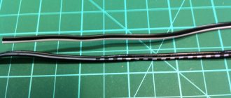
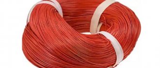
SIP-2 wire with zero insulated core
SIP-2 is part of a group of self-supporting cables equipped with insulation that supply electricity by air to various social facilities (residential buildings, etc.). In addition, it is used in the field of outdoor lighting networks. The wire can be used in both normal and aggressive (salt and high humidity) or industrial environments. In the photo above - SIP-2 with zero insulated core.
There are other types that differ in design:
- SIP-1 – neutral conductor without insulation (for overhead power lines and branches to buildings, currently no longer produced );
- SIP-3 – insulated and has one core (high-voltage lines);
- SIP-4 – complete absence of a supporting core (2-4 twisted wires, for branches).
Types of self-supporting insulated wire (SIP)
For main wires with aluminum stranded and compacted conductors, cross-linked polyethylene insulation is used, which increases resistance to ultraviolet radiation, the external environment and prolonged exposure to temperatures up to 900 C. The current-carrying conductors are “wound” onto the neutral conductor, which is divided into two types: it can be both without insulation (types SIP-1) and with its presence (SIP-2, SIP-3, SIP-4).
The resistance values of the neutral core must be equal to the standards indicated in the table:
| Core cross-section, mm2 | 25 | 35 | 50 | 54.6 | 70 | 95 |
| Resistance, Ohm/km | 1.38 | 0.986 | 0.72 | 0.63 | 0.493 | 0.363 |
| Number of wires | 2-7 | 2-7 | 2-7 | 2-7 | 2-7 | 2-7 |
| Minimum tensile strength, KN | 7.4 | 10.3 | 14.2 | 16.6 | 20.6 | 27.9 |
| Wire weight (without container), kg/km | 670 | 770 | 907 | — | 1170 | 1265 |
The resistance of phase conductors differs from the resistance of zero conductors.
Standard sizes
Area of the main cores and permissible current loads for them:
- 16 mm2 - 100 A;
- 25 mm2 - 130 A;
- 35 mm2 - 160 A;
- 50 mm2 - 195 A;
- 70 mm2 - 240 A;
- 95 mm2 - 300 A;
- 120 mm2 - 340 A;
- 150 mm2 - 380 A;
- 185 mm2 - 436 A;
- 240 mm2 - 515 A;
Current loads are indicated for an air temperature of 25 °C, wind speed of 0.6 m/s and ultraviolet radiation of 1000 W/m2; for other conditions, correction factors are applied.
The cross-section of the load-bearing core has an area (in mm2):
- 25;
- 35;
- 50;
- 70;
- 95
Table 1. Brief technical characteristics of SIP wires
| Wire brand | SIP-1 | SIP-2 | SIP-3 | SIP-4 | SIP-5 |
| Number of current-carrying cores, pcs | 1 ÷ 4 | 1 ÷ 4 | 1 | 2 — 4 | 2 — 4 |
| Core cross-section, mm2 | 16 ÷ 120 | 16 ÷ 120 | 35 ÷ 240 | 16 ÷ 120 | 16 ÷ 120 |
| Zero core, bearing | aluminum alloy (with steel cores) | aluminum alloy (with steel cores) | absent | absent | absent |
| Conductor | aluminum | aluminum | aluminum alloy (with steel cores) | aluminum | aluminum |
| Voltage class, kV | 0.4 ÷ 1 | 0.4 ÷ 1 | 10 ÷ 35 | 0.4 ÷ 1 | 0.4 ÷ 1 |
| Core insulation type | thermoplastic polyethylene | light stabilized polyethylene | light stabilized polyethylene | thermoplastic polyethylene | light stabilized polyethylene |
| Operating temperature | -60оС ÷ +50оС | -60оС ÷ +50оС | -60оС ÷ +50оС | -60оС ÷ +50оС | -60оС ÷ +50оС |
| Permissible heating of cores during operation | +70оС | +90оС | +70оС | +90оС | +90оС |
| min wire bending radius | not less than 10 Ø | not less than 10 Ø | not less than 10 Ø | not less than 10 Ø | not less than 10 Ø |
| Life time | at least 40 years | at least 40 years | at least 40 years | at least 40 years | at least 40 years |
| Application |
| — | — for installation of overhead lines with voltage 10-35 kV |
| — |
Positive qualities of SIP-2
- Can be used on common supports near other wires;
- Reduced cost of use;
- In case of unintended contacts with live phase conductors, it is safe;
- The line works even if the wires are jammed;
- When a current-carrying wire comes into contact with grounded elements, short circuit is excluded;
- Simplicity of design, you can increase the distance between supports;
- Difficulty of unauthorized connection;
- No need to replace insulators;
- You can make repairs without disconnecting the line voltage;
- The inductive reactance is 2.5-3 times lower due to insulation, unlike the AC wire.
Advantages of SIP wires
- Significant reduction in costs for both maintenance and installation of lines. This is due to the reliability of the lines - the absence of short circuits when the wires get caught due to strong winds. Ingress of foreign objects due to good core insulation. “Dance of wires” - accumulation of snow, as well as the formation of ice.
- When installing SIP, all wire fastenings are connected with special fittings, as a result of which there is no need to use traverses and insulators, which reduces costs.
- Possibility of installing SIP on existing low and high voltage overhead lines, as well as communication overhead lines.
- Thanks to good insulation, line losses are reduced.
- It is possible to connect to a 0.4 kV line under voltage.
- Possibility of using voltage classes 0.6, 1 kV, and 20 kV in power lines at temperatures from -50° C to +50° C
- Higher fire safety of SIP.
- More aesthetic appearance than conventional bare wires. For example, entering a house.
- SIP insulation can withstand the harmful effects of ultraviolet sunlight for a long time.
- The service life of SIP is more than 25 years.
Technical characteristics of SIP-2
Cross-linked polyethylene plays a huge role in wire insulation. It significantly improves its characteristics: wear resistance, elasticity, resistance to high temperatures.
| № | Section | Harness diameter, mm | Reeling weight, kg/km | Current strength in operating mode, A | |
| Phase wire | Lighting wire | ||||
| 1 | 3×25+54,6 | 24 | 531 | 112 | — |
| 2 | 3×25+54,6+16 | 25 | 600 | 112 | 83 |
| 3 | 3×25+54,6+2×16 | 26.5 | 670 | 112 | 83 |
| 4 | 3×35+54,6 | 24.6 | 641 | 138 | — |
| 5 | 3×35+54,6+16 | 25.5 | 710 | 138 | 83 |
| 6 | 3×35+54,6+2×16 | 27.5 | 779 | 138 | 83 |
| 7 | 3×50+54,6 | 27 | 770 | 165 | — |
| 8 | 3×50+54,6+16 | 28.5 | 839 | 165 | 83 |
| 9 | 3×50+54,6+2×16 | 30 | 907 | 165 | 83 |
| 10 | 3×70+54,6 | 30 | 985 | 180 | — |
| 11 | 3×70+54,6+16 | 32.2 | 1054 | 180 | 83 |
| 12 | 3×70+54,6+2×16 | 33 | 1122 | 180 | 83 |
| 13 | 3×95+70 | 35 | 1130 | 258 | — |
| 14 | 3×95+70+16 | 36 | 1200 | 258 | 83 |
| 15 | 3×95+70+2×16 | 37 | 1265 | 258 | 83 |
| 16 | 3×120+70 | 37 | 1380 | 300 | — |
| 17 | 3×120+70+16 | 38 | 1450 | 300 | 83 |
| 18 | 3×120+70+2×16 | 39 | 1520 | 300 | 83 |
| 19 | 3×150+70 | 40 | 1749 | 344 | — |
| 20 | 3×150+70+16 | 41 | 1817 | 344 | 83 |
| 21 | 3×150+70+2×16 | 42 | 1885 | 344 | 83 |
SIP-2 is designed for the following temperature conditions:
- ambient temperature – from -600С to +500С;
- maximum operating temperature of the cable – 900C;
- limit value for overload (about 8 hours per day) – 1300C;
- heating of cores during short circuit (up to 5 sec.) – 2500C;
- permissible bending radius of the cable is at least 10 diameters.
Types and purpose
SIP wire is a popular brand of cable products, as it is optimal for connecting electricity to a private home. It has a relatively low price and good technical characteristics. There are three types:
- with bare carrier neutral;
- isolated carrier neutral;
- self-supporting.
He can often be seen in the private sector and not only
SIP conductors are made of aluminum, and the carriers are made of aluminum alloy with greater load-bearing capacity. Different types of these cable products differ in insulation material, have different technical characteristics and scope of application.
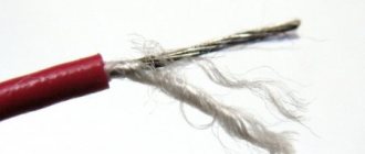
With uninsulated neutral (SIP-1)
SIP wire with uninsulated neutral is AMKA according to the European standard. It consists of:
- 1-4 aluminum conductors insulated with light-stabilized cross-linked polyethylene;
- 1 supporting bare wire made of aluminum alloy or pure aluminum.
This is what SIP wire 1 looks like
SIP1 is used when laying main transmission lines and branches from them in dry and normal air with a low degree of pollution. Designed for networks with a rated voltage of 0.6 kV and 1 kV (different types, see technical specifications) and a frequency of 50 Hz.
Maximum current loads SIP-1
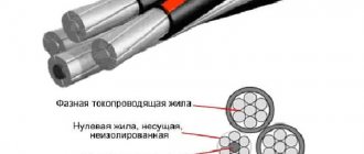
Insulated conductors are twisted with a certain pitch around the supporting core. Current-carrying conductors can be monocore (one wire) or consist of several round compacted conductors. The neutral conductor usually consists of a steel or aluminum core around which round aluminum (or alloy) conductors are located and has a load-bearing conductor usually of a larger diameter.
During installation, the weight of the suspended cable is carried by the core without insulation - it is hooked onto guy wires, attached to poles, etc. It is to increase the load-bearing capacity that it is made of a larger diameter than the others. Typically this bare conductor is used as a neutral. Current-carrying conductors are insulated. Thermoplastic polyethylene is used, which can withstand long-term heating up to 60-70°C, short-term heating up to 125°C. The power line built on SIP-1 is capable of withstanding heavy snow loads.
Technical characteristics of Wires SIP-1
The disadvantage of this system is that in the event of a phase imbalance, dangerous voltage can occur on the bare wire. To prevent this situation, the neutral wire at each pole is grounded. However, it is not laid along the facades of houses, since theoretically it can be dangerous.
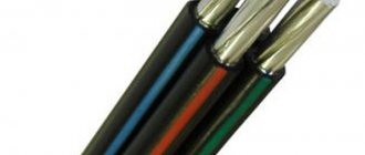
SIP wire with insulated neutral (SIP-2, SIP-3)
Self-supporting wire with an insulated neutral - SIP 2 and SIP-3 - differs from the previous version in that the neutral wire has a protective sheath. Everything else remains unchanged:
- 1-4 conductive (phase) cores in a sheath made of light-stabilized cross-linked polyethylene;
- 1 supporting wire in the same insulation.
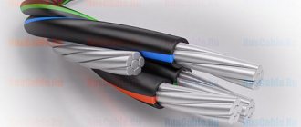
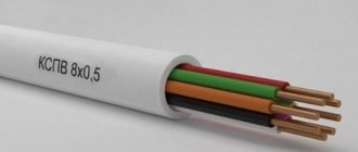
Appearance of SIP-2 wire
SIP-2 is used in networks with a rated voltage of 0.6 kV and 1 kV, with the only difference being that it can be used in a humid climate or in an atmosphere with a high salt content (coasts of seas, oceans, salt marshes, etc.), lead along the walls of residential buildings. It is SIP-2 that is usually used if it is necessary to connect electricity from a pole to a house.
Maximum current loads SIP-2
SIP-3 has the same structure, but a thicker shell and is called a protected wire. This self-supporting wire can be used in networks with a higher rated voltage: SIP-3-20 - up to 20 kV, SIP-3-35 - up to 35 kV. In terms of technical parameters (operating temperature, maximum heating, etc.) this wire is the same as SIP-1. So this data can be taken from the table in the previous paragraph. The permissible current loads differ (see table).
Maximum current loads of SIP-3 depending on the cross-section of phase conductors
Wires SIP-2 and SIP-3 are also suspended from the supporting conductor (it is larger in diameter). Since the wire is insulated, there is no danger of current pickup, but there is a possibility of the sheath breaking under heavy mechanical load. Therefore, when designing lines based on SIP-2, the spans are reduced (poles are installed more often).
Self-supporting wires without supporting cores (SIP-4, SIP-5, SIP-7)
Structurally, these self-supporting wires differ from previous modifications. They do not have a supporting conductor and the load is distributed across all cores. In terms of strength, they are inferior to modifications with a dedicated support wire. Therefore, in regions with snowy winters or frequent icing, they should not be used. The number of conductors in self-supporting wires is from 2 to 4; they can be with one or two additional lighting wires. All wires are twisted around a common center with a certain pitch. One of the cores is used as neutral, the rest as phase.
The SIP-4 wire is designed for networks with a maximum voltage of 0.6 kV or 1 kV. Due to the absence of a thicker core, this cable is more flexible - the minimum bending radius is 7.5 cable radii.
SIP-4 is different in that the physical load from the mass of the cable and precipitation is distributed among all the cores
This type of self-supporting wire is more popular because it has a lower cost and good characteristics. Several more varieties are available:
- SIPn-4. It features flame retardant insulation.
- SIPsn-4. The insulation is non-flammable, the design has 1 or 2 additional wires for lighting. It may have 1.2 or 3 auxiliary cores for control circuits (copper, with a cross-section of 1.5 mm², 2.0 mm², 4.0 mm². In this case, the number of signal or lighting cores is added to the formula describing the cable through plus. : SIP-4 2*30 +1*16 (four conductive cores with a diameter of 30 mm and one auxiliary core with a diameter of 16 mm).
- SIPgsn-4. It differs from the previous type in that it has a water-blocking element in the conductor.
In a climate with little snow, the route from the pole to the house can be completed with SIP-4
Options SIPsn-4 and SIPgsn-4 have a European analogue AsXSn, similar in many characteristics and purpose.
There is also a SIP-5 wire. It differs in that it cannot have additional lighting or signal wires. Only insulated conductors of the same diameter. The number of cores is two, three or four. One of them is neutral, the rest are phases.
Type SIP-7 - single-core wire with reinforced multilayer insulation:
- screen over a conductor made of electrically conductive PE;
- cross-linked PE insulation layer;
- layer of weather-resistant tracking-resistant PE.
Characteristics of SIP-5
Self-supporting wire SIP-7 is designed for networks with rated voltages up to 110 kV. They can be used where underground installation is not possible and the use of bare wires is unacceptable. These are park areas and densely populated areas. Suitable for use in tropical, temperate and cold climates.
Fittings for SIP-2
1. The carrier neutral is clamped into anchor wedge clamps (the insulation is not removed). During installation, the cable is located inside a clamp made of aluminum alloy and fixed with plastic wedges (Fig. A). Types of clamps: RA-1000, RA-1500, RA-2000.
2. Prefabricated support clamps PS-16/95 and intermediate suspension kit ES-1500, made of weather-resistant plastic, are designed for hanging wires on corner and intermediate supports (Fig. B). Together with galvanized steel brackets, they form supporting units.
3. Connecting clamps brand MJPT and MJPT-N (for neutral).
Electrical characteristics of SIP wires
wire SIP 1 SIP 2 electrical characteristics"> wire SIP3 electrical characteristics"> wire SIP4 electrical characteristics"> wire SIP5 electrical characteristics"> wire SIP5 mechanical characteristics">
SIP installation
The basis for mounting the wire is made up of brackets; they are secured to the supports with steel mounting tape F207. All work related to the installation is mechanized. If the wire cross-section does not exceed 50 mm2, then manual rolling of SIP is permissible. A drum with a wire is installed near the support, and a rope is attached to its end. Rollers for rolling are placed at the top of the supports. During the installation process, they support the SIP, which is pulled by a rope. Laying the wire on the ground or in contact with the structure (supports) is not allowed, as this may compromise the integrity of the insulation! In the last meters of the section, the zero load-bearing core is fixed with a clamp to the final support. The load-bearing core is pulled through using a winch. The force is controlled using a dynamometer. When the wire hangs loose, it needs to be checked for sag, and then tightened completely. The zero core is secured with a clamp at the initial section, after which the winch is removed. The neutral wire is transferred from the rollers to the supporting clamps. Having finished with this, you can remove the rolling rollers. Next, the SIP line is connected with the bare ends of the wires, using crimping in the sleeve (Fig. B).
Self-supporting insulated wire is one of the best of its kind. It does not require insulators or special supports. But installation requires high-level electricians equipped with a full set of all necessary tools.
Disadvantages of SIP wires
Along with the undeniable advantages, there are also some disadvantages of SIP wire.
- SIP wire is more expensive than insulated wires A and AC;
- Domestic energy systems are not quite ready for the transition to isolated overhead lines. This is largely due to the lack of information, regulatory documentation, and personnel trained to work with SIP wire.
SIP wire was first used in France and Finland. It was in these countries that for the first time in Europe they began to develop methods for using SIP wires, as well as standards and rules for the construction of overhead lines with insulated and protected wires.
Later, air suspension systems for SIP wires began to be developed in other countries. They were based on standards approved in Europe.