A flexible conductor is required for the electrical connection of equipment operating under shaking and vibration conditions. The installation wire PuGV has gained particular popularity. A successful design ensures reliable installation of machine tools, electrical machines and mechanisms. The availability of the material makes it possible to lay stationary networks in industrial premises and housing with a rated alternating current voltage of up to 450V.
The material in this article will help you get acquainted with this wonderful product, characteristics, and applications.
Description and design of the PuGV wire
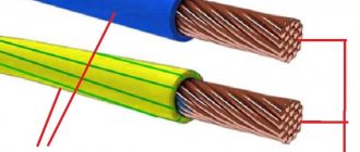
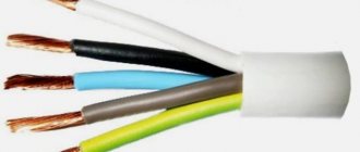
Installation wire PuGV is a wire with one flexible copper core, with PVC insulation, without a sheath.
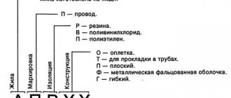
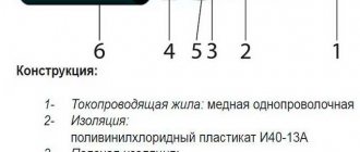
Explanation of the designation:
absence of the letter “A” at the beginning – copper core; “Pu” - installation wire; “G” - for installation conditions requiring increased flexibility; “B” - PVC insulation, including low fire hazard and heat-resistant;
Designation example: PuGV-2.5 - PuGV wire with a conductor cross-section of 2.5 mm2
Since PuGV installation wires are intended mainly for industrial use and are designed for a long service life, GOST sets strict requirements for finished products in terms of structural, electrical and mechanical parameters. The values of individual parameters are also regulated for the period of operation and storage.
The range of produced cross-sections of PuGV installation wires is from 0.5 to 95 mm2.
The cores must be twisted from individual wires (at least 7 wires for sections up to 1.5 mm2 inclusive and with the diameter of individual wires for the most used sections not exceeding that indicated in the table).
| Section | Diameter of individual wire, mm |
| 2,5 | 0,43 |
| 4 | 0,53 |
| 6 | 0,65 |
| 10 | 0,82 |
| 16 | 0,65 |
| 25 | 0,82 |
| 35 and 50 | 0,69 |
The insulation must fit tightly to the core and be removed without damaging the core. The nominal and minimum values of the radial insulation thickness and the maximum outer diameter for wires of the most commonly used sections up to 50 mm2 are given in the table.
| Nominal cross-section, mm 2 | Nominal insulation thickness, mm | Minimum insulation thickness, mm | Maximum outer diameter, mm |
| 0,75 | 0,6 | 0,44 | 2,6 |
| 1,0 | 0,7 | 0,53 | 2,8 |
| 1,5 | 0,7 | 0,53 | 3,1 |
| 2,5 | 0,8 | 0,62 | 3,9 |
| 4 | 0,8 | 0,62 | 4,4 |
| 6 | 0,8 | 0,62 | 4,9 |
| 10 | 1,0 | 0,8 | 6,4 |
| 16 | 1,0 | 0,8 | 8,0 |
| 25 | 1,2 | 0,98 | 9,8 |
| 35 | 1,2 | 0,98 | 11,0 |
| 50 | 1,4 | 1,16 | 13,0 |
It is allowed to repeat the configuration of the current-carrying core on the insulation surface within permissible deviations.
PuGV wires must be made in various colors. The coloring must be solid or done by applying two longitudinal stripes to the insulation of a natural color, located diametrically. For single-core wires used for grounding purposes, the insulation should be a solid yellow-green color.
The color of solid insulation or longitudinal strips must be specified in the order (the letters indicated in the table are added to the wire designation when ordering, for example: PuGV-2.5 Zh).
| Designation | Color |
| White, natural or gray | B |
| Yellow or orange or purple | AND |
| Red or pink | TO |
| Blue or cyan | WITH |
| Green | Z |
| Brown | Kch |
| Black | H |
| Yellow-green | Z-Z |
If there is no indication of a specific color in the order, the manufacturer supplies wires at its discretion, while it is allowed to supply wires with insulation of transitional and mixed colors (designation “BC”) in a volume of no more than 10% of the batch.
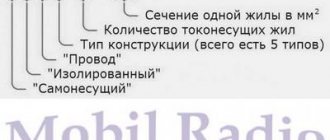
Explanation of markings
Wire PV 3
Marking abbreviation for wires PuGV decoding:
- In the absence of the letter “A”, indicating that the product is made of aluminum, the material is copper;
- “P” means that the product is a wire, capital “u” means installation;
- This letter is usually used to mark the insulation material. If the wire belongs to the 5th class of flexibility, then the letter “G” is inserted - flexible;
- Vinyl insulation is designated by the letter “B”;
- Shell filled with plastic compound made of vinyl – “B”;
- If there are capital letters or combinations of letters, this means additional characteristics. For example, ng means non-flammable; ng ls – during forced combustion, it emits almost no toxic substances and smoke; ng hf – non-flammable with corrosion protection; ng frls - has increased fire resistance in the absence of smoke in the event of forced combustion;
- Next are numbers indicating the number of cores, conductors in the core and the cross-sectional area of each conductor in mm².
The PuGV cable is a single wire. PuGVV contains several conductors laid in parallel, connected by a PVC sheath. The last letter “B”, the second after the designation of the type of insulation, indicates the material, which means the presence of a sheath, and therefore belongs to multi-core cables. Therefore, an abbreviated decoding is used for the PuGV cable.
Roll of wire
Technical characteristics of PuGV wire
The electrical resistance of current-carrying conductors at direct current for wires with a cross-section of up to 50 mm2 upon acceptance and delivery must be no more than that indicated in the table. For wires with a cross section of 0.75; 1 and 1.5 mm 2 core resistance depends on the core design.
| Nominal conductor cross-section, mm2 | 0,75 | 1,0 | 1,5 | 2,5 | 4 | 6 | 10 | 16 | 25 | 35 | 50 |
| Copper conductor resistance, Ohm/km | 24,5-25,5 | 18,1-21,8 | 12,1-14,0 | 7,41 | 4,61 | 3,11 | 1,99 | 1,21 | 0,809 | 0,551 | 0,394 |
For the period of operation and storage, it is allowed to increase the specified resistance values of the cores by 20%.
The electrical insulation resistance per 1 km of length at a temperature of 20°C must be at least 1 MOhm upon acceptance and delivery and at least 0.01 MOhm for the period of operation and storage.
Upon acceptance and delivery, finished wires must withstand, when immersed in water without preliminary exposure to it, testing with an alternating voltage of 2000 V at a frequency of 50 Hz for 5 minutes, applied between the conductor and water (for the period of operation and storage - 1000 V under the same conditions).
The wires must withstand winding at a temperature of minus 15°C into a cylinder (drum) with a diameter equal to 5 outer diameters of the wire (on a special installation directly in the refrigerating chamber).
Application area
The wire described is a type of multifunctional material. The wide range of cross-sectional areas (0.5-240 mm²) and high flexibility with low resistivity make it applicable in many areas of electronics and mechanical engineering.
Terminal box
Interesting. Cars, motorcycles, scooters and other vehicles when organizing electrical wiring give preference to PuGV wires.
Labeling requirements
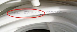
Wires must have the manufacturer's designation and the wire identification, which must be made in the form of a continuous marking on the insulation surface. The marking may be printed, embossed or stamped onto the surface of the wire. The distance from the end of the marking to the beginning of the next one should not exceed 500 mm. It is allowed to mark wires with a cross-section of up to 6 mm2 in the form of a distinctive thread or colored stripes or solid marks.
The label attached to the coil or drum, or on the cheek of the drum, must indicate:
— trademark of the manufacturer; — symbol of the wire (full, indicating the number of cores and cross-section); — length in meters; — gross weight (for drums) in kilograms — date of manufacture (year, month); — GOST designation.
The label must bear a technical control stamp and a certification mark.
For wires supplied on a drum, the label attached to the coil or drum, or on the cheek of the drum, must indicate the number of sections and their length through a plus sign from the top to the bottom layers in meters.
Transportation and storage
Transportation and storage of wires and cords must comply with GOST 18690-2012.
Transportation and storage conditions regarding exposure to climatic factors must comply with GOST 15150 group 8.
Transportation conditions in terms of exposure to mechanical factors must comply with group Zh according to GOST 23216.
Warranty period - 3 years. The warranty period is calculated from the date of putting wires and cables into operation, but no later than 6 months from the date of manufacture.
Weight and size parameters of PuGV wire
Approximate weights of the most common wire cross-sections for packaging and transportation purposes are given in the table. The given values may differ for wires of different batches and manufacturers by 10% less or more.
| Section | Weight value for packaging and transportation purposes, kg/km |
| 0,75 | 12 |
| 1,0 | 14 |
| 1,5 | 20 |
| 2,5 | 31 |
| 4 | 48 |
| 6 | 70 |
| 10 | 116 |
| 16 | 182 |
| 25 | 287 |
| 35 | 378 |
| 50 | 520 |
PuGV wire load currents
Permissible load currents for wires are not regulated in GOST. In accordance with the PUE, for any installation method it is recommended that for single wires not exceed the load currents indicated in the table.
| Nominal conductor cross-section, mm2 | Permissible load current, A |
| 0,75 | 15 |
| 1,0 | 17 |
| 1,5 | 23 |
| 2,5 | 30 |
| 4 | 41 |
| 6 | 50 |
| 10 | 80 |
| 16 | 100 |
| 25 | 140 |
| 35 | 170 |
| 50 | 215 |
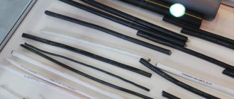
Cable products and metal mesh
Design:- The conductor is made of annealed copper wire of class 1, 2 or 5 according to GOST 22483.
- Insulation is made of polyvinyl chloride plastic.
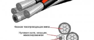
- The insulated cores of PuVV grade stranded wire are laid parallel in one plane. The insulated cores have a distinctive color.
Color scheme:
| Green-yellow*, blue*, brown | Brown, black, gray | |
| 4 | Green-yellow*, brown, black, gray | Blue*, brown, black, gray |
| 5 | Green-yellow*, blue*, brown, black, gray | Blue*, brown, black, gray |
* Green-yellow color is used to indicate the earth conductor (PE). Blue color is used to indicate the neutral wire (N).
- The shell is made of PVC plastic with filling.
Application:
The wires are used for electrical installations for stationary installation in lighting and power networks, as well as for installation of electrical equipment, machines, mechanisms and machine tools, internal electrical installations for rated alternating voltage up to 450/750 V inclusive, rated frequency up to 400 Hz or direct voltage up to 1000 V inclusive .
Wires in design, technical parameters and operational characteristics comply with the requirements of international standards IEC 60227-1:2007, IEC 60227-3:1997, IEC 60227-4:1997.
PuV wire for laying in steel pipes, boxes, trays, etc., for installation of electrical circuits
PuGV wire is used for installation in steel pipes, boxes, trays, etc., for installation of electrical circuits where increased flexibility during installation and installation is required.
PuVV wire is used for laying under plaster, in concrete, brickwork, in the voids of building structures, as well as openly along the surface of walls and ceilings and in other structures, for installation of electrical circuits
PuGVV wire is used for laying under plaster, in concrete, brickwork, in the voids of building structures, as well as openly on the surface of walls and ceilings and in other structures, for installation of electrical circuits where increased flexibility during laying and installation is required
The wires do not spread flame when laid alone.
Fire hazard class according to GOST 31565-2012:
O1.8.2.5.4
Specifications:
Type of climatic modification UHL, placement category 2 according to GOST 15150-69
Requirements for resistance to external influences:
— wires are resistant to elevated ambient temperatures up to 65°C
— wires are resistant to low ambient temperatures down to -50°C
— wires are resistant to high relative air humidity up to 98% at ambient temperatures up to +35°C;
Installation of wires is carried out at a temperature not lower than -15°C
Bend radius during installation:
- for wires of the PuV, PuVV brand - at least 10D
- for wires of the PuGV, PuGVV brand - at least 5D
Long-term permissible heating temperature of cores during operation, no more than +700C
Warranty service life: 3 years
Construction length - at least 100 m
The service life of wires during operation is at least 20 years provided that the consumer complies with the requirements for transportation, storage, installation and operation. The service life is calculated from the date of manufacture of the wires.
OKP codes:
35 5113 1
Tabular data
Nominal outer diameter and estimated weight of PuVV wire
| Number and nominal cross-section of conductors, mm2 | Nominal diameter ( dimensions | Estimated weight of 1 km of wire, kg |
| 1×0.50 | 3.4 | 18 |
| 1×0.75 | 3.6 | 21 |
| 1×1.0 | 3.7 | 25 |
| 1×1.5 | 4.2 | 33 |
| 1×2.5 | 5.0 | 49 |
| 1×4 | 5.5 | 66 |
| 1×6 | 6.0 | 88 |
| 1×10 | 7.2 | 137 |
| 1×16 | 8.9 | 217 |
| 1×25 | 10.6 | 328 |
| 1×35 | 11.8 | 432 |
| 1×50 | 13.7 | 583 |
| 1×70 | 15.5 | 802 |
| 1×95 | 17.8 | 1092 |
| 1×120 | 19.4 | 1347 |
| 1×150 | 22.4 | 1703 |
| 1×185 | 25.0 | 2136 |
| 1×240 | 28.1 | 2758 |
| 1×300 | 31.3 | 3449 |
| 1×400 | 34.7 | 4346 |
| 2×0.50 | 3.4×5.4 | 33 |
| 2×0.75 | 3.57×5.74 | 39 |
| 2×1.0 | 3.73×6.06 | 46 |
| 2×1.5 | 4.18×6.96 | 62 |
| 2×2.5 | 4.98×8.36 | 94 |
| 2×4 | 5.45×9.3 | 129 |
| 3×0.50 | 3.4×7.4 | 47 |
| 3×0.75 | 3.57×7.91 | 57 |
| 3×1.0 | 3.73×8.39 | 67 |
| 3×1.5 | 4.18×9.74 | 92 |
| 3×2.5 | 4.98×11.7 | 139 |
| 3×4 | 5.45×13.2 | 191 |
Nominal outer diameter and estimated wire weight
| Nominal cross-section of current-carrying conductor, mm2 | Nominal wire diameter, mm | Estimated weight of 1 km of wire, kg | ||||
| PuV | PuGV | PuGVV | PuV | PuGV | PuGVV | |
| 0.50 | 2.0 | 2.1 | 3.5 | 8.5 | 9.4 | 19.7 |
| 0.75 | 2.2 | 2.3 | 3.8 | 11.1 | 12.6 | 23.8 |
| 1 | 2.3 | 2.5 | 3.9 | 13.9 | 15.4 | 27.1 |
| 1.5 | 2.8 | 3.0 | 4.4 | 20.2 | 22.0 | 35.4 |
| 2.5 | 3.4 | 3.6 | 5.1 | 32.0 | 34.9 | 50.8 |
| 4 | 3.9 | 3.9 | 5.8 | 47.0 | 51.1 | 71.7 |
| 6 | 4.4 | 4.7 | 6.9 | 66.8 | 74.2 | 99.6 |
| 10 | 5.6 | 6.0 | 8.4 | 111 | 122 | 154 |
| 16 | 7.1 | 7.6 | 9.8 | 180 | 184 | 226 |
| 25 | 8.8 | 9.6 | 11.7 | 283 | 280 | 330 |
| 35 | 10.0 | 10.9 | 13.2 | 381 | 397 | 454 |
| 50 | 11.7 | 12.6 | 15.6 | 517 | 558 | 633 |
| 70 | 13.5 | 14.6 | 17.6 | 728 | 761 | 846 |
| 95 | 15.8 | 17.2 | 19.7 | 1005 | 1026 | 1123 |
| 120 | 17.4 | 18.8 | 22.0 | 1252 | 1267 | 1378 |
| 150 | 19.4 | 21.0 | 25.0 | 1541 | 1584 | 1731 |
| 185 | 21.6 | 23.4 | 27.4 | 1932 | 1939 | 2101 |
| 240 | 24.7 | 27.3 | 30.7 | 2527 | 2537 | 2748 |
| 300 | 27.5 | 31.0 | 34.6 | 3161 | 3169 | 3409 |
| 400 | 30.9 | 34.5 | 38.6 | 4025 | 4142 | 4447 |
Permissible current loads for PuVV brand wire
| Number and nominal cross-section of conductors, mm2 | Current load, A, no more, at | |
| T*tpzh=700С T**amb.=200C | T*tpzh=350С T**amb.=250C | |
| 1×0.50 | 13 | 5 |
| 1×0.75 | 16 | 6 |
| 1×1.0 | 19 | 8 |
| 1×1.5 | 25 | 10 |
| 1×2.5 | 34 | 13 |
| 1×4 | 46 | 18 |
| 1×6 | 59 | 22 |
| 1×10 | 82 | 31 |
| 1×16 | FROM | 41 |
| 1×25 | 151 | 53 |
| 1×35 | 186 | 65 |
| 1×50 | 226 | 77 |
| 1×70 | 286 | 95 |
| 1×95 | 351 | 114 |
| 1×120 | 407 | 130 |
| 1×150 | 457 | 145 |
| 1×185 | 522 | 164 |
| 1×240 | 618 | 191 |
| 1×300 | 705 | 215 |
| 1×400 | 819 | 246 |
| 2×0.50 | 10 | 4 |
| 2×0.75 | 13 | 5 |
| 2×1.0 | 15 | 6 |
| 2×1.5 | 20 | 7 |
| 2×2.5 | 27 | 10 |
| 2×4 | 37 | 13 |
| 3×0.50 | 9 | 3 |
| 3×0.75 | 12 | 4 |
| 3×1.0 | 14 | 5 |
| 3×1.5 | 18 | 6 |
| 3×2.5 | 25 | 9 |
| 3×4 | 34 | 11 |
| Т*тпж - temperature of the conductor. T**amb - ambient temperature. | ||
Permissible current loads for wires of brands PuV, PuGV, PuGVV.
| Nominal cross-section of current-carrying conductor, mm2 | Current load, A, no more, at | |||||
| T*tpzh=700С T**amb.=200C | T*tpzh=350С T**amb.=250C | |||||
| PuV | PuGV | PuGVV | PuV | PuGV | PuGVV | |
| 0.50 | 11 | 11 | 13 | 4 | 4 | 5 |
| 0.75 | 14 | 15 | 16 | 6 | 6 | 6 |
| 1.0 | 17 | 17 | 19 | 7 | 7 | 8 |
| 1.5 | 23 | 23 | 25 | 9 | 9 | 10 |
| 2.5 | 32 | 32 | 34 | 13 | 13 | 13 |
| 4 | 43 | 43 | 46 | 17 | 17 | 17 |
| 6 | 56 | 59 | 61 | 22 | 22 | 23 |
| 10 | 80 | 117 | 119 | 30 | 43 | 43 |
| 16 | 112 | 115 | 115 | 41 | 41 | 41 |
| 25 | 152 | 154 | 152 | 53 | 53 | 53 |
| 35 | 188 | 193 | 191 | 65 | 65 | 64 |
| 50 | 230 | 246 | 241 | 77 | 80 | 80 |
| 70 | 292 | 305 | 298 | 96 | 97 | 96 |
| 95 | 359 | 362 | 353 | 115 | 114 | 112 |
| 120 | 418 | 427 | 415 | 132 | 131 | 129 |
| 150 | 475 | 491 | 475 | 148 | 148 | 146 |
| 185 | 546 | 553 | 535 | 167 | 165 | 162 |
| 240 | 646 | 651 | 627 | 194 | 191 | 188 |
| 300 | 741 | 750 | 723 | 220 | 216 | 213 |
| 400 | 860 | 881 | 845 | 251 | 250 | 247 |
| Т*тпж - temperature of the conductor. Т**amb - ambient temperature. | ||||||
Available methods for quality control of PuGV wire
Control methods are presented that, while not strictly complying with GOST, allow preliminary conclusions to be drawn about the quality of the wire if the measured values differ significantly from the regulated ones. The final conclusion about the compliance of the wire with GOST can be made only after testing the wire in a specialized laboratory using strict methods and in the volumes specified in GOST.
Visual inspection. The following can be checked: marking, number of wires in the core, color and integrity of the insulation.
Measuring structural dimensions. The insulation thickness and outer diameter can be checked using suitable measuring instruments. Measuring the wire diameter dpr and calculating the cross-section of the core using the formula 0.785dpr2N (where N is the number of wires in the core) is not a strict method for controlling the cross-section of the cores, because confirmation of cross-section compliance is electrical resistance, however, a significant deviation of the calculated cross-section from the nominal (more than 10%) may serve as a basis for doubts about the quality.
Measuring the electrical resistance of current-carrying conductors. It can be carried out on the finished wire with an ohmmeter with a suitable measurement limit (with a small cross-section and the normal length of the wire in a coil or on a drum can be several Ohms) and recalculated to a length of 1 km. Particular attention should be paid to making good contact with the test leads.