Commercial metering of electrical energy
Technical requirements for the installation of measuring systems
commercial electricity metering
Requirements for estimated electricity meters
Metering devices are a set of devices that provide measurement and metering of electricity (current and voltage measuring transformers, electrical energy meters, telemetric sensors, information and measuring systems and their communication lines) and are interconnected according to an established scheme.
Electric energy meter is an electrical measuring device designed to account for consumed electricity, alternating or direct current. The unit of measurement is kWh or Ah.
Electric energy meter is an electric energy meter designed for commercial settlements between market entities.
To account for electrical energy, electricity meters are used, the types of which are approved by the federal executive body for technical regulation and metrology and are included in the state register of measuring instruments.
Technical parameters and metrological characteristics of electric energy meters must meet the requirements:
GOST 52320-2005 Part 11 “Electric energy meters”; GOST R 52323-2005 Part 22 “Static active energy meters of accuracy classes 0.2S and 0.5S”; GOST R 52322-2005 Part 21 “Static active energy meters of accuracy classes 1 and 2”;
GOST R 52425−2005 “Static reactive energy meters”.
It is recommended to install meters for calculating the energy supply organization with electricity consumers at the boundary between the network (by balance sheet) of the network organization and the consumer.
If the calculated metering device is not located on the border of the balance sheet of electric networks, the volume of electrical energy received into the electric networks (released from electric networks) is adjusted taking into account the amount of standard losses of electrical energy that occur in the section of the network from the border of the balance sheet of electric networks to the location installation of a metering device, unless a different adjustment procedure is established by agreement of the parties.
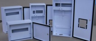
Meters should be located in dry rooms that are easily accessible for maintenance, in a place that is sufficiently free and not cramped for work. General industrial meters are not allowed to be installed in rooms where, due to production conditions, the temperature can often exceed +40°C, as well as in rooms with aggressive environments. It is allowed to place meters in unheated rooms and corridors of switchgears of power plants and substations, as well as in outdoor cabinets. If the devices are not intended for use in conditions of negative temperatures, they must be permanently insulated for the winter using insulating cabinets, hoods with heated air inside them with an electric lamp or heating element to ensure a positive temperature inside the hood, but not higher than +20 °C.
Meters must be installed in cabinets, chambers of complete switchgears (KRU, KRUN), on panels, switchboards, in niches, on walls with a rigid structure. The height from the floor to the meter terminal box should be within 0.8-1.7 m. A height of less than 0.8 m is allowed, but not less than 0.4 m.
In places where there is a danger of mechanical damage to meters or their contamination, or in places accessible to unauthorized persons (passages, staircases, etc.), a locked cabinet with a window at dial level should be provided for meters. Similar cabinets should also be installed to co-locate meters and current transformers when performing metering on the low voltage side (at the consumer input).
The designs and dimensions of cabinets, niches, panels, etc. should provide convenient access to the terminals of meters and current transformers. In addition, it must be possible to conveniently replace the meter. The design of its fastening must ensure the possibility of installing and removing the meter from the front side.
If there are several connections at the facility with separate electricity metering, the meter panels must contain inscriptions with the names of the connections.
At 0.4 kV connections with a load up to 100 A inclusive, use direct-connection electricity meters.
For three-phase input, use three-element electricity meters.
Newly installed three-phase meters must have state verification seals no more than 12 months old, and single-phase meters must have state verification seals no more than 2 years old. The presence of a valid verification of the electricity meter is confirmed by providing a supporting document - a passport form for the electricity meter or a verification certificate. The documents for the electricity meter must contain notes about the settings of the tariff schedule and local time.
The main technical parameter of an electricity meter is the “accuracy class,” which indicates the level of measurement error of the meter. In accordance with the section “Rules for organizing electricity metering in retail markets” of the “Basic provisions for the functioning of retail electricity markets”, approved by Decree of the Government of the Russian Federation dated May 4, 2012 No. 442, the requirements for settlement electricity meters, depending on the category of consumers, should be as follows :
| Consumer category | Accuracy class | Additional requirements |
| To account for electrical energy consumed by consumers with a maximum power of at least 670 kW | 0.5S and higher | Metering devices must be able to measure hourly volumes of electrical energy consumption and provide storage of data on hourly volumes of electrical energy consumption for the last 90 days or more or be included in the metering system |
| To account for electrical energy at the interface between electrical grid facilities and in-house engineering systems of an apartment building, the connection of which to the electrical grid facilities is carried out after the entry into force of the “Basic provisions for the functioning of retail electricity markets”, approved by Decree of the Government of the Russian Federation dated May 4, 2012 No. 442 | 1,0 and higher | |
| To account for electrical energy consumed by consumers with maximum power less than 670 kW and voltage at points of connection to electrical grid facilities of 35 kV and below (10 kV, 6 kV, 380 V, 220 V) | ||
| To account for electrical energy consumed by citizens | 2,0 and higher | |
| To account for electrical energy at the interface between electrical grid facilities and in-house engineering systems of an apartment building |
Requirements for instrument transformers
According to the technical requirements, measuring current transformers must comply with GOST 7746-2001 (“Current transformers. General technical conditions”).
Instrument voltage transformers according to their technical characteristics must comply with GOST 1983-2001 (“Voltage transformers. General technical conditions”).
The accuracy class of current transformers and the voltage for connecting calculated electricity meters must be no more than 0.5.
It is allowed to use current transformers with an increased transformation ratio (according to the conditions of electrodynamic and thermal resistance or busbar protection), if at the maximum load of the connection the current in the secondary winding of the current transformer is at least 40% of the rated current of the meter, and at a minimum operating load - at least 5 %.
The connection of the current windings of the meters to the secondary windings of the current transformers should be carried out separately from the protection circuits.
The use of intermediate current transformers to switch on metering meters is prohibited.
When connecting the meter semi-indirectly, it is necessary to install current transformers in all phases.
Current transformers used to connect meters at voltages up to 0.4 kV must be installed after switching devices in the direction of power flow.
The terminals of the secondary measuring windings of current transformers must be isolated from the terminals without control shorting or circuit breakage, using sealed covers and screens.
To ensure the safety of work carried out in the circuits of measuring instruments, relay protection devices and electrical automation, the secondary circuits (windings) of measuring current transformers must have permanent grounding.
Grounding in the secondary circuits of current transformers should be provided at the terminals of the current transformers.
The current transformer must have a valid primary (factory) or periodic verification (in accordance with the verification interval specified in the description of the type of this measuring instrument). The presence of a valid verification is confirmed by providing original passports or certificates of verification of current transformers with verification protocols.
For three-phase input, use three-phase voltage transformers or groups of single-phase voltage transformers.
To protect the measuring circuits, it must be possible to seal the grilles and doors of the chambers where fuses are installed on the high and low voltage side of the voltage transformers, as well as the drive handles of the voltage transformer disconnectors. If it is impossible to seal the chambers, the terminals of the voltage transformers are sealed.
To ensure the safety of work carried out in the circuits of measuring instruments, relay protection devices and electrical automation, the secondary circuits (windings) of voltage measuring transformers must have permanent grounding.
The secondary windings of the voltage transformer must be grounded by connecting the neutral point or one of the ends of the winding to a grounding device. Grounding of the secondary windings of a voltage transformer must be carried out, as a rule, at the terminal assembly closest to the voltage transformer or at the terminals of the voltage transformer.
The voltage transformer must have a valid primary (factory) or periodic verification (in accordance with the verification interval specified in the description of the type of this measuring instrument). The presence of a valid verification is confirmed by providing original passports or certificates of verification of the voltage transformer with verification protocols.
Requirements for measuring circuits
The presence of rations in the electrical wiring to the settlement meters is not allowed.
Installation of direct and alternating current circuits within switchboard devices (panels, consoles, cabinets, boxes, etc.), as well as internal connection diagrams of drives of switches, disconnectors and other devices, according to the conditions of mechanical strength, must be made with wires or cables with copper conductors . The use of wires and cables with aluminum conductors for internal installation of switchboard devices is not allowed.
To protect the measuring circuits, it must be possible to seal intermediate terminal blocks, test blocks, boxes and other devices included in the measuring circuits of electricity meters, while the use of such devices must be minimized.
When connecting the meter semi-indirectly, connect the conductors of the voltage circuits to the busbars using a separate technological bolt connection, in close proximity to the current transformer of this measuring complex. The places where the meter voltage circuits are connected to current-carrying parts of the network must be isolated from without controlled disconnection.
The load of the secondary windings of the instrument transformers to which the meters are connected should not exceed the rated values.
The cross-section and length of wires and cables in the voltage circuits of the calculated meters must be selected such that the voltage loss in these circuits is no more than 0.25% of the rated voltage.
For an indirect meter connection scheme, the secondary circuits should be routed to independent terminal assemblies or sections in a common row of terminals. If clamp assemblies are not available, test blocks must be installed. The clamps must ensure short-circuiting of the secondary circuits of current transformers, disconnecting the meter's current circuits and voltage circuits in each phase of the meters when replacing or checking them, as well as turning on the model meter without disconnecting wires and cables. The design of assemblies and terminal boxes for metering meters must ensure the possibility of sealing them.
When connecting the meter semi-indirectly, VVG cable 3 x 2.5 mm2 with insulation of cores of different colors should be used as a conductor of secondary circuits to current transformers.
Requirements for input devices and switching devices at the input
It must be possible to carry out a complete visual inspection from stationary sites of input devices, overhead lines, cable lines, as well as input equipment to metering electrical wiring to identify electrical receivers before metering connection. Places of possible connection before metering must be isolated by sealing chambers, cells, cabinets, etc.
For loads up to 100 A inclusive, avoid installing switches before the installation site of the metering unit.
For safe installation and replacement of meters in networks with voltages up to 380 V, it must be possible to turn off the meter by switching devices or fuses installed before it at a distance of no more than 10 m. Voltage relief must be provided from all phases connected to the meter.
Installation of equipment for automatic transfer of reserve, security and fire alarms and other automatic equipment should be provided after the installation site of the metering unit.
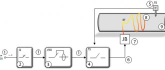
Connection diagrams for electric meters
The connection diagrams for electricity meters presented below are typical and may differ depending on the manufacturer and installation location. When installing electricity meters, you must be guided by the manufacturer's passport for this product.
Connection diagram for a single-phase electricity meter
Connection diagram for a three-phase electricity meter (direct connection)
Connection diagram for an electricity meter to a three-phase three-wire or four-wire network using 3 current transformers (semi-indirect connection)
Diagram for connecting an electricity meter to a three-phase three-wire or four-wire network using 3 current transformers and 3 voltage transformers
(indirect connection)
Which company to choose
Due to the fact that electric meters are installed for decades, you should buy the device from reliable manufacturers. In the future, this will avoid problems with equipment replacement, documentation and measurement accuracy.
In Russia there are three reliable manufacturers of electricity metering devices:
- Taypit (Neva);
- Inotex (Mercury);
- Energy meter.
All three are large companies with over 10 years of experience; experts recommend choosing devices from these companies.
Installation and configuration of equipment
You can connect current sensors and configure the controller yourself: no special tools or dangerous high-voltage work are required. Connecting and setting up the controller takes about 15 minutes.
Instructions and answers to frequently asked questions from users in the Support section.
Do you want to save time and quickly deploy a solution on a complex object?
Order turnkey implementation from our dealers.Select an installer
Control via browser and mobile application
Analyze your energy consumption via a web browser or the SAURES mobile app. Build graphs with detail by month, day and hour for the required period. We guarantee free storage of an annual archive of readings.
The SAURES personal account is provided free of charge. You will only be charged for additional options.
Test the Cloud and mobile application right now.
It's free and doesn't require registration. Test
TOP popular models
Let's look at the most popular models of electricity metering devices. All of them have the necessary certificates and licenses.
Single-phase single-tariff
Neva 103 1SO. Voltage 220-230 volts, current 5/60 amperes. Operates at temperatures from -40 to +60 °C. First class accuracy. Intervalidation interval is 16 years. This device is easy to install, as it is mounted using a DIN rail. The model is small in size, but the meter readings are easy to read - the numbers are clearly visible. The service life of such a device is up to 30 years.